 Juan Carlos Soldado1
 Apostolos Pesyridis1,2
 Panos Sphicas3*
 Pantelis Nikolakopoulos4
 Christos N. Markides5
 Michael Deligant6
- 1Center for Advanced Powertrain and Fuels Research (CAPF), Department of Mechanical and Aerospace Engineering, Brunel University London, Uxbridge, United Kingdom
- 2College of Engineering, Alasala University, Dammam, Saudi Arabia
- 3Department of Mechanical Engineering, Prince Mohammad Bin Fahd University, Dhahran, Saudi Arabia
- 4Machine Design Laboratory, Department of Mechanical Engineering and Aeronautics, University of Patras, Patras, Greece
- 5Clean Energy Processes (CEP) Laboratory, Department of Chemical Engineering, Imperial College London, London, United Kingdom
- 6DynFluid Lab - EA92, Arts et Métiers ParisTech, Paris, France
Despite the high thermal efficiency achieved by modern heavy-duty diesel engines, over 40% of the energy contained in the fuel is wasted as heat either in the cooling or the exhaust gases. By recovering part of the wasted energy, the overall thermal efficiency of the engine increases and the pollutant emissions are reduced. Organic Rankine cycle (ORC) systems are considered a favourable candidate technology to recover exhaust gas waste heat, because of their simplicity and small backpressure impact on the engine performance and fuel consumption. The recovered energy can be transformed into electricity or directly into mechanical power. In this study, an axial turbine expander for an ORC system was designed and optimized for a heavy-duty diesel engine for which real-world data were available. The impact of the ORC system on the fuel consumption under various operating points was investigated. Compared to an ORC system equipped with a radial turbine expander, the axial design improved fuel consumption by between 2 and 10% at low and high engine speeds. Finally, the benefits of utilising ORC systems for waste heat recovery in heavy-duty trucks is evaluated by performing various drive cycle tests, and it is found that the highest values of fuel consumption were found in the NEDC and the HDUDDS as these cycles generally involve more dynamic driving profiles. However, it was in these cycles that the ORC could recover more energy with an overall fuel consumption reduction of 5 and 4.8%, respectively.
Introduction
Waste heat recovery (WHR) from reciprocating internal-combustion engines, whether in automotive/transport (Milkov et al., 2015) or stationary power generation or co-generation applications (Simpson et al., 2019; Le Brun et al., 2020) can increase overall efficiency, and reduce fuel consumption and emissions. The transportation sector in particular has been growing and is currently responsible for almost 15% of global energy consumption. On-road transportation is responsible for 12% and light and heavy-duty engines for 8% of the overall energy consumption (Cipollone et al., 2016). The automotive industry is currently intensifying research due to severe regulations on exhaust gas emissions (Di Battista et al., 2015). An analysis of the European Commission showed that over 80% of greenhouse gases emitted from human activities into the atmosphere are composed of carbon dioxide (Milkov et al., 2015). Of that percentage, around a quarter is attributable to transport. Even though the overall efficiency of modern engines for optimum operating load may reach up to 37%, the typical on-road performance is closer to 20% (Johnson, 2007).
Waste heat recovery (WHR) technologies are becoming increasingly practical for use in heavy-duty diesel engines (Teng et al., 2007), primarily based on: thermoelectric generation (TEG), turbocompounding (TC) and the organic Rankine cycle (ORC) (Karvountzis-Kontakiotis et al., 2016). Stobart and Milner (2009); Stobart et al. (2010) performed experimental studies proving that TEG can produce fuel savings between 3.9 and 4.7%. Nevertheless, this technology is still at early stages of development, and some materials and manufacturing methods make it an expensive option especailly in larger-scale transport WHR applications. Wilson (1986) reported that mechanical turbocompounding can improve brake specific fuel consumption by up to 6%. Furthermore, electrical turbocompoundingcan contribute to fuel saving of over 5% (Hopman, 2004). In recent years, WHR systems based on ORC systems have been at the focal point of research for road vehicle applications (Peralez et al., 2017). ORC systems offer potentially higher efficiencies, for on-road vehicle engines, than turbocompound and TEG (Jeihouni et al., 2016). In this work, an axial turbine for an ORC WHR system was designed and optimized to determine the feasibility of this technology in automotive applications and to allow for a direct impact assessment of axial vs. radial turbine expanders in automotive applications under representative, legislated drive cycle scenarios.
Waste Heat Recovery—General and ORC Considerations
Generally, the typical on-road efficiency of an IC engine is about 20% as part of the energy released by the fuel is lost in the exhaust and cooling systems (Johnson, 2007). Heavy-duty diesel engines under optimum conditions could reach an efficiency of over 40% (Teng et al., 2007). WHR technologies can be used to recover part of the wasted energy. WHR involves capturing and reusing the waste heat energy for generating mechanical or electrical work. The temperature of the wasted heat is a measure of availability and quality. The higher the temperature, the greater the amount of energy that can be extracted and recuperated (Moroz et al., 2015).
Regarding automotive applications, WHR is gaining more significance. In theory, it is possible to increase the efficiency by up to 20% by incorporating such technologies. Although there are some key points to consider:
• The development of a thermodynamic cycle and components in compliance with the automotive constraints;
• The minimization of the impact on the vehicle architecture and performance;
• The cost sustainability and the feasibility of the technology;
• The compliance with the current and future GHG emissions regulations.
The energy recovered from the exhaust of an IC engine will lead to an improvement of fuel consumption and increase of engine power, or even engine-downsizing, to further reduce emissions.
Despite these advantages, there are still some challenges for ORC WHR in automotive applications. First, creating a compact WHR unit which integrates the turbine expander, the pump and the generator. Second, integrating the WHR unit with the engine and the exhaust system, especially in part-load and transient operation. Third, innovating control strategies for an efficient utilisation of the heat at part-load conditions. Fourth, improving the heat rejection and reducing the cooling drag. Finally, WHR systems must be able to integrate in a vehicle with a hybrid powertrain.
General
The Rankine cycle is a closed-loop thermodynamic cycle which converts heat into mechanical power. This mechanical power can be used to perform mechanical work or to produce electricity. Using a high molecular mass organic fluid, with low boiling point, allows for the recovery of heat from low temperature heat sources, which for a great number of applications would be unusable. The layout of a basic Rankine cycle system and a T-s cycle diagram are presented in Figure 1A. The first step in this cycle uses engine exhaust to heat the fluid up in an evaporator in order to capture the waste heat available (Process 2–3). The superheated vapour (point 3) then passes through a turbine expander to generate mechanical or electrical power; this device can be either a positive displacement machine or a turbomachine (process 3–4). After the fluid undergoes expansion, it flows through a condenser in order to discharge low-grade thermal energy to the atmosphere (Process 4–1).
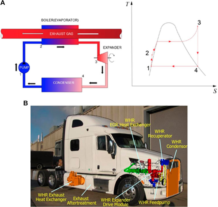
FIGURE 1. (A, top) Rankine cycle system layout and T-s cycle diagram and (B, bottom) installation of the waste heat recovery (WHR) system in a Class 8 tractor.
An important advantage of the ORC WHR is that the efficiency of the ORC is not dependent on the exhaust gas pressure. Thus, the efficiency is only affected by the temperature and the mass flow rate of the exhaust gases (Moroz, 2015). Also, the use of organic fluids suppresses the need of incorporating a superheater in the design.
On the other hand, ORC systems present some drawbacks which can complicate their implementation in certain types of vehicles. In light-duty vehicles packaging and low cycle efficiency due to the inherently low temperature of the heat source (relative to conventional power generation applications), especially at low and part-loads, can be a problem (Moroz, 2015). In heavy-duty vehicles, the available energy in the exhaust is higher and the space not as limited as in smaller vehicles. Cummins (2006) successfully integrated its ORC system to a Class 8 tractor, Figure 1B.
Another disadvantage concerning ORC systems is the working fluid. Common working fluids are sometimes flammable and toxic. The selection of the optimum working fluid is vital.
ORC systems can produce either mechanical or electrical power from the recovered heat. One solution is to deliver the mechanical power generated by the expander of the Rankine cycle to the powertrain system of the IC engine. According to Sprouse and Depcik (2013), reciprocating expanders have good controllability with respect to the response to fluctuating waste heat conditions. Furthermore, the expander can be coupled to the engine either directly or via a belt transmission. However, the use of a turbine is not that simple, as its rotational speed is approximately ten times higher than that of the combustion engine, therefore, direct coupling is not possible. Moreover, as the efficiency of the turbine is bound to its rotational speed, the matching process seems complicated even for a gearbox.
When producing electrical power, the expander can be connected to a generator either through a shaft or a gearbox. There are various options to utilise the electrical power. As the ORC system can produce up to a 10% of the engine power, one option is to feed the power to the alternator. Or the energy can be saved in batteries for use in other vehicle systems, such as the air conditioning, or to hybrid systems.
The economic feasibility of these systems in automotive applications depends, beyond the capital cost of the technology itself, on the fuel price and the prevailing emissions regulations. The capital cost of an ORC system, depends highly on the chosen technological solution, the size of the production series and the modularity of the system (Sprouse and Depcik, 2013).
Working Fluids
The selection of a suitable working fluid is a fundamental step in the optimum design of ORC systems as the performance and efficiency of the system will be influenced by the working fluid (Vivian et al., 2015). The working fluids can be divided into three groups according to the slope of the condensation curve in the T-S diagram: wet, dry and isentropic, as shown in Figure 2A. Isentropic and dry fluids are preferred as they prevent condensation in the expander and a superheater is not needed (Moroz, 2015).
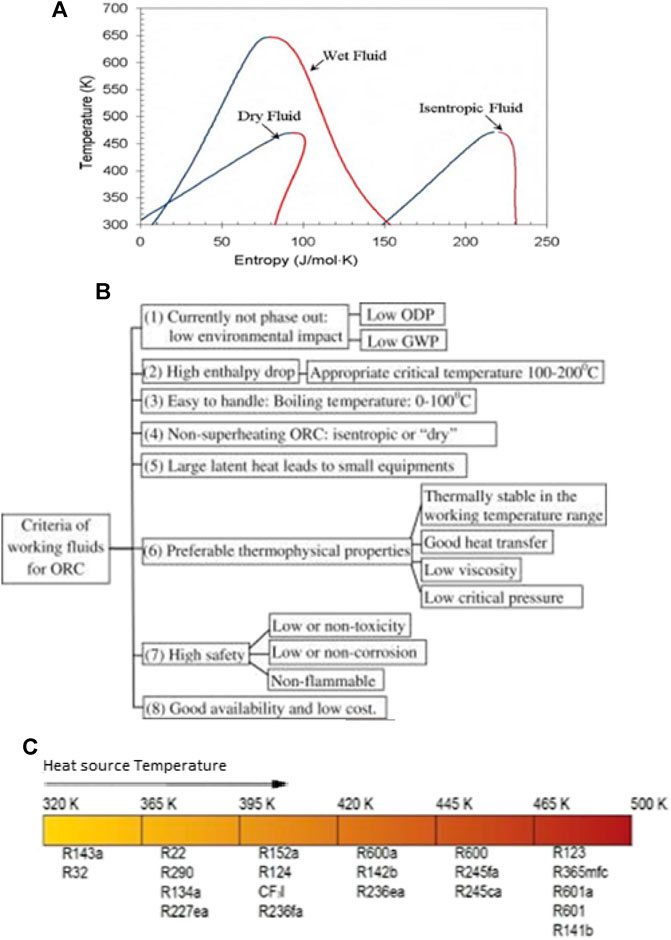
FIGURE 2. (A) Slope of the saturation curve of an organic fluid (Moroz et al., 2015), (B) Criteria for ORC working fluid selection and (C) suitable organic fluids classified by the heat source temperature (Milkov et al., 2015).
In the literature there is great number of studies on the selection of optimum working fluids for ORC systems depending on the application. However, there is no clear consensus on the identification of any particular optimal fluid (Chen et al., 2010; Vivian et al., 2015). Several authors have provided guidelines or indicators to follow to select the most optimum working fluids, as illustrated in Figure 2B (Qiu, 2012; Kulkarni and Sood, 2015). Many researchers identify the temperature of the heat source as the main criterion for choosing the ORC working fluid (Milkov et al., 2015). However, the boiling point of the fluid, shown in Figure 2C, cannot be the only criterion, as the cost and the environmental impact must be considered as well (Eichler et al., 2015). Nouman (2012) carried out a comparative study of more than 100 fluids from different perspectives and concluded that the final selection should be a trade-off between thermodynamic, environmental and safety properties.
The most commonly used fluids are: R134a, R245fa, R1233zde and ethanol (water mixtures). In this study, Novec 649 was also investigated. Datla and Brasz (2014) compared R245fa and R1233zd for low-temperature ORC applications, with preferred by numerous ORC OEMs (Honeywell 2010). Honeywell compared R245fa with R134a and water, among other fluids in ORC applications and produced a study to replace the first two for low global warming fluids (Zyhowski et al., 2010).
Expanders
In addition to the selection of the working fluid, the selection of the expander type plays a critical role in the design, operation and overall performance of ORC systems. The selection of the expander depends on the working fluid, the expander type, the shaft speed, pressure ratio, inlet temperature, mass flow rate and the nominal power range, or overall system scale (Moroz et al., 2015). ORC expanders can be divided into two categories: volumetric expanders and turbines. Volumetric expanders operate on the principle of reversed volumetric compressors use in refrigeration cycles and heat pump applications. The most common volumetric expanders are screw (Alshammari et al., 2018a; Pantaleo et al., 2019), piston (Markides et al., 2013; Chatzopoulou et al., 2019) and scroll (Capata and Hernandez, 2014).
ORC WHR turbines are either radial or axial. In large scale ORCs, the turbine expanders are mainly based on conventional turbine technology with shaft seals, reduction gear, air cooled generator and lubricating oil system. However, the interest towards small scale ORC is increasing, especially for waste heat recovery in automotive applications. In systems which produce a small power output, volumetric expanders are considered, due to their good off-design performance compared to small scale turbomachinery (Sprouse and Depcik, 2013).
The energy in the exhaust system of a vehicle is low compared to industrial plants. The automotive ORC systems produce less power, operate at moderate pressure ratios and have lower efficiency compared to industrial turbines. So volumetric expanders may not be the best solution for automotive applications. On the other hand, the design of turbines is challenging as they tend to be small and operating at high speed, with high relative losses. Additionally, organic fluids have a low speed of sound, leading to supersonic flows which create increased losses. However, due to the small specific enthalpy drop and large volumetric flow rate, it is possible to design turbines with relatively simple geometry and good efficiency (Pesiridis, 2014). According to Moroz et al. (2015), the application of turboexpanders ranges from power ratings of 10 kW to over 1 MW, with radial turbines preferred for applications under 500 kW and axial turbines for more than 500 kW.
Drive Cycles
A drive cycle is the representation of vehicle speed vs. time. It is a very powerful tool for assessing the fuel consumption and emissions of different vehicles and WHR systems. The driving cycle is usually performed on a chassis dynamometer where tailpipe emissions are collected and analysed. Alternatively, the driving cycle is performed on an engine mounted on an engine dynamometer by controlling the engine torque and speed (Nicolas, 2013).
There are two types of drive cycles, the modal cycles like the European standard NEDC, or Japanese 10–15 mode and the transient cycles like the FTP-75 or Artemis cycle. The modal cycles are a compilation of straight acceleration and constant speed periods and are not representative of a real driver behaviour, whereas transient cycles involve many speed variations, typical of on-road driving conditions (Nicolas, 2013).
The drive cycles used for this study are the New European Driving Cycle (NEDC), the Artemis Highway driving cycle, the Highway Fuel Economy Test Cycle (HWFET) and the EPA Heavy Duty Urban Dynamometer Driving Schedule (HDUDDS).
The NEDC was the reference cycle in Europe for light duty-vehicles until Euro6. The NEDC comprises an urban part called ECE, which is repeated four times, and an extra-urban part, the EUDC. More suitable for assessing heavy-duty vehicles are the other three driving cycles. The Artemis cycle is based on a statistical study carried out in Europe. The HWFET is used to assess fuel economy over a highway driving cycle. The HDUDDS cycle has been developed for chassis dynamometer testing of heavy-duty vehicles (ECOpoint, 2017). The characteristics of these cycles are summarised in Figure 3.
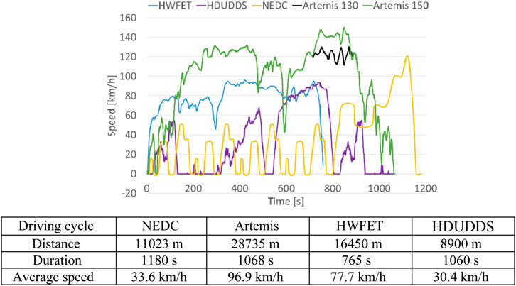
FIGURE 3. Velocity profiles over time for the drive cycles employed in this study with tabulated principal specifications for the drive cycles employed in this study, below.
Methodology
General
Following the previous literature survey, the engine and the ORC were modelled using the GT-Power gas dynamics code. A MATLAB code was developed to calculate the parameters of the ORC turbine using as input the data obtained from the GT-Power models. With the MATLAB-calculated parameters, the turbine CAD model was created in SolidWorks. Then, Computational Fluid Dynamics (CFD) analysis of the designed turbine was performed using ANSYS CFX. The CFD-analysis was an iterative process whose outputs optimized the turbine geometry. Then the turbine map was generated and the radial turbine substituted in the ORC system. The results obtained from the simulations of the new ORC system were implemented in the various drive cycles to analyse the generated power and the reduction in the fuel consumption under realistic vehicle driving conditions. The methodological approach used in this work is illustrated in Figure 4.
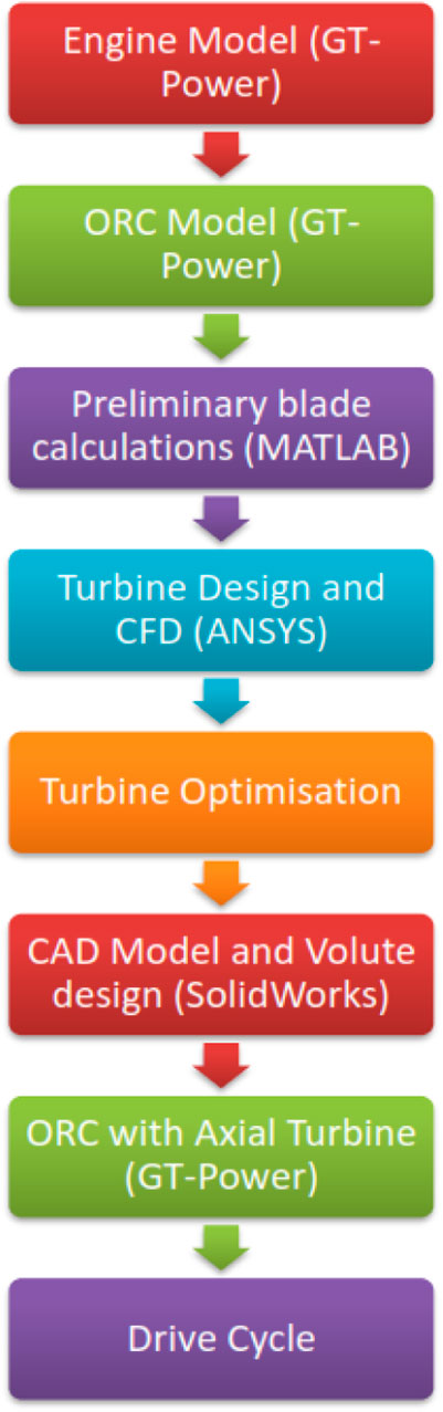
FIGURE 4. Methodology applied in this work.
CFD Analysis
All simulations were performed in ANSYS CFX with the aim of optimizing the geometry of the turbine to obtain a high power with moderate isentropic efficiency. This was achieved as seen earlier in this paper. Figure 5 represents the meridional view of the turbine stator (red) and rotor (blue).
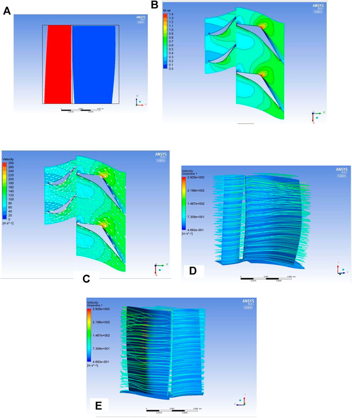
FIGURE 5. (A) Meridional view of the turbine stator (red) and rotor (blue) and (B) relative mach number field in stator-rotor couple and (C) velocity streamlines in stator-rotor couple; (D) velocity streamlines showing no vorticity, and (E) supersonic flow identification in a single rotor-stator couple.
The MATLAB code maintained the relative Mach number below unity. Figure 5B is a section of the stator and rotor. The relative Mach number is displayed in the whole domain. There was no supersonic flow in the stator and only a small region in the rotor where there was a minimal area where the flow reached of supersonic velocity at 40% chord length.
The effect of that pointed shape can be seen better when plotting the streamlines of the velocity. The streamlines flowed along the wall and, at the point of the curvature, joined adjacent streamlines producing flow acceleration. Despite the supersonic velocity regions, the streamlines illustrate a smooth flow transition in Figure 5C.
Figure 5D, on the other hand, illustrates the flow passing through the rotor-stator system profile. No recirculation vortices are present due to the sufficient blade twist being applied through the application of free vorticity at design stage. However, in Figure 5E, the flow reaches supersonic velocities in the upper side of the rotor profile. In addition, the small clearance set between the rotor tip and the shroud does not allow for significant cross-over flow over the rotor blade, indicating reduced loses.
Engine Modelling
The IVECO Cursor 11A, 6-cylinder, heavy-duty diesel engine was chosen as the baseline engine for this work as shown in Figure 6A. The power and torque curves, from the manufacturer, were set as a target for the model. The engine model was later used to connect the ORC to the exhaust system. The engine and ORC simulation was developed in the commercial software GT-Power.
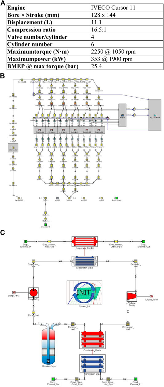
FIGURE 6. Engine and engine-ORC model specifications (A) IVECO Cursor 11 specifications (B) GT-Power engine model and (B) GT-Power ORC cycle system model
The exhaust-gas temperature and the mass flow rate were calculated for various operating points as shown in Figure 6A. These values were then used for the calculation of the ORC WHR system. The completed GT-Power model is shown in Figure 6B.
In addition to the engine model, the ORC was also modelled in GT-Power. The model consisted of a shell and tube evaporator, a plate condenser, a reservoir, a pump and an expander, as shown in Figure 6C. Running several simulations using the same setup for every fluid the choice was made based on the working fluid which had the better performance in terms of power produced and efficiency of the expander; that fluid was R134a.
After the selection of the working fluid, the final model was generated. The following assumptions were made (Andwari et al., 2017) and input were as shown in Table 1:
• No pressure losses in the evaporator and the condenser;
• The organic fluid exit temperature from the evaporator, equals to the exhaust gas temperature;
• The organic fluid exit temperature from the condenser equals the coolant temperature.
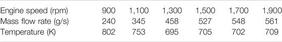
TABLE 1. ORC inputs as calculated from GT-Power engine model.
The efficiency of the ORC was calculated from (Alshammari et al., 2018b):
where Wt is the turbine power output and Qin the heat available in the evaporator.
The net power was calculating by subtracting the power of the pump from the turbine power:
The BSFC was calculated from:
where mf is the fuel mass flow rate and Pb is the brake power of the engine. However, due to the additional power recovered from the ORC, the new BSFC was calculated from:
Turbine Rotor Design
Before designing the turbine, the operating conditions had to be specified from GT-Power simulation. The turbine is part of the ORC heat recovery system of a heavy-duty diesel vehicle such as a truck. Therefore, the engine will mostly operate around medium rpm so the design point was considered accordingly. The engine speed of 1,200 rpm was chosen as the point from which the data in the simulation were used for the preliminary calculations of the blade geometry.
For optimizing the blade geometry, in addition to the above initial conditions for the engine, the following initial conditions were used for the turbine:
• Turbine rotational speed—60,000 rpm
• Blade speed (U)—120 m/s
• Flow coefficient (&phiv)—1.2
• Nozzle loss coefficient (λ)—0.5
In addition to the values of temperature, pressure and mass flow rate obtained in the simulation, the diameter of the inlet pipe in the ORC model was considered as a geometrical constraint for the maximum radius at the tip of the turbine. Furthermore, the number of blades were unknown as well as the blade height.
A MATLAB code was developed to use the previous conditions and assumptions as input. As there were multiple parameters, the code performed iterations for different number of blades and a range of values for the mean turbine radius. The minimum blade height was set as a constraint.
The stator and rotor blades were drawn in ANSYS Geometry, as cambered airfoils, as shown in Figure 7.
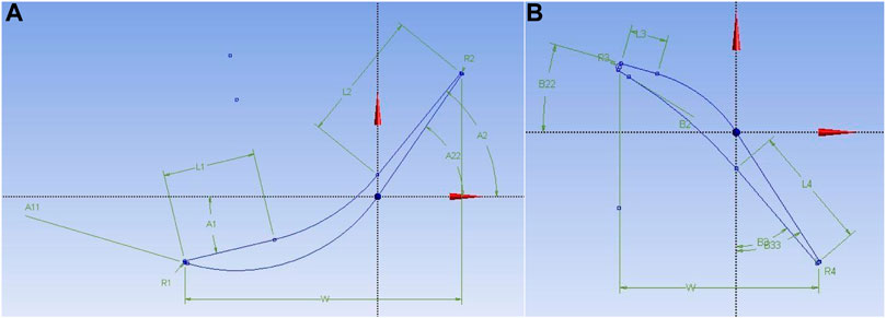
FIGURE 7. Stator (A) and rotor (B) blade geometry.
For designing the blades, first, three planes were created at a distance equivalent to the hub, mean and tip radii. The next step was to draw the profile of the blade using straight lines, arcs and tangents. For drawing the profiles, the initial values for the following parameters were calculated using the aforementioned MATLAB code: leading inner angle, leading outer angle, leading radius, leading length, trailing length, trailing inner angle, trailing outer angle, trailing radius and chord. The values of these parameters were later modified for the optimization analysis. The tool skin joined the three profiles generating the full body of the blade. The following step was to create the flow path. This was done on the xz-plane or yz-plane as the axis of rotation was the z-axis as defined in the theoretical chapter. In addition, a surface element containing the blade profile was generated. The final step was to use the function export points. By selecting the flow path and the surface element, as well as the number of blades of the stator, a domain for meshing was produced and transferred to TurboGrid.
Computational Fluid Dynamics Methodology
Mesh
The CFD analysis was crucial for defining the performance of the turbine. The blade design was meshed using the TurboGrid module of ANSYS Workbench. Figure 8 shows the meshed domain, which is enclosed between the inlet, outlet, hub and shroud. To reduce the computational cost of the simulation, only one blade of the rotor and one of the stator were meshed. The position of the inlet and outlet boundaries were modified depending on the blade total length.
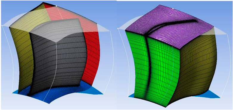
FIGURE 8. Turbogrid mesh detail of turbine rotor.
To generate the mesh, in TurboGrid the number of nodes option was chosen. The total number of nodes was divided by two and 200,000 nodes were allocated to each blade, allowing for extra nodes for changes in the geometry of the blade during optimization. In order to get more accurate results, the mesh around the blade surface, hub and shroud was refined.
Solver
The solver used for the CFD analysis was CFX of the ANSYS package. After importing into CFX the meshes of the stator and rotor blades, these were positioned so that both domains were very close to each other but without intersecting. The stator mesh was set as a stationary mesh whereas the rotor mesh was defined as rotating around the z-axis. Finally, the working fluid R134a was assumed an ideal gas with properties calculated by REFPROP software.
Boundary Conditions
The stator and rotor domains were established as stationary and rotating, respectively, with R134a as the working fluid with heat transfer modelled within ANSYS, as well. Generally, in the simulation of axial turbines, the total pressure and temperature are imposed at the inlet of the stator while the static pressure is imposed in the outlet of the rotor. These values were obtained from the simulations performed in GT-Power. No-slip condition was imposed on the walls of the blades, hub and shroud. The shroud was considered counter-rotating due to the rotational movement of the rotor mesh. Symmetry conditions were set on the surfaces in-between the blades of the stator and the rotor.
Convergence Criteria
The convergence control was set to 200 iterations with a physical timescale of 0.001 s and a residual target for convergence to 0.00001. Additional parameters were monitored to check that the simulation was producing appropriate results. For instance, the mass flow rate difference between inlet and outlet had to be zero. Also, the total-to-static efficiency was monitored for this single-stage turbine set-up.
Blade Optimization
Preliminary blade calculations were performed by the MATLAB code. The first parameters to be optimized were the number of blades on the stator and rotor. Then the geometry of the stator blades was optimized, followed by the geometry of the rotor blades. Optimization started from the hub moving to the tip. The parameters of each blade profile were optimized for highest efficiency, parametrically, in the following sequence: leading inner angle, leading outer angle, leading radius, leading length, trailing length, trailing inner angle, trailing outer angle, trailing radius and chord. The resulting models can be found in Figure 9.
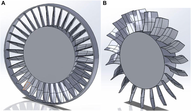
FIGURE 9. Stator (A) and rotor (B).
Implementation of the ORC Turbine
Once the design of the axial turbine was optimized, more simulations were performed in ANSYS CFX for various rotational speeds and outlet pressures. Thus, an ORC turbine map was generated. The map was then implemented in the ORC and engine models in GT-Power. The GT-Power then simulated the power generated by the ORC turbine, the power of the pump and the heat exchanged in the evaporator and condenser. Therefore, the efficiency of the ORC system was calculated.
Drive Cycle Modelling
A series of drive cycles were simulated on GT-Power on the modelled engine with and without the ORC WHR system. The BSFC, BMEP and FMEP maps obtained for the modelled engine with and without the ORC WHR system were used as inputs to the drive cycles. The cycles simulated were the New European Driving Cycle (NEDC), Artemis, HWFET and UHDDS. Fuel consumption in l/100 km was calculated under realistic driving conditions.
Results and Discussion
Data from the engine, the ORC system, the CFD simulations and drive cycle simulation is analysed and evaluated.
Engine Model
The investigated IVECO 11 engine, produces the, provided by the manufacturer, power and torque curves shown in Figure 10 (b). The geometry of the cylinders and other specifications, presented in Figure 3, were used as an input to the GT-Power model. The simulated power and torque curve for the engine are, also, shown in Figure 10A. There is good agreement between the manufacturer data and the GT-Power model. Furthermore, the values provided by the manufacturer and the values simulated in GT-Power are compared in Figure 10B. The relative error has higher values in the low engine speeds at the torque simulation.
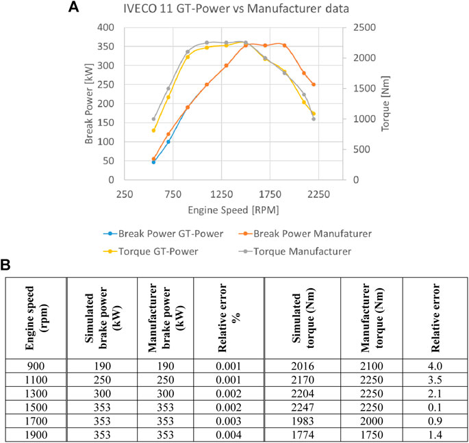
FIGURE 10. (A) Power and torque curves simulated on GT-Power and provided by the manufacturer and (B) power and torque values simulated on GT-Power and provided by the manufacturer.
The simulated BMEP at maximum torque was 25.4 bar, which was the same value given by the manufacturer. The manufacturer BSFC at maximum power and maximum torque are 196 and 194 g/kWh, respectively. Whereas the calculated values for the BSFC were around 200 g/kWh.
To validate the model developed in GT-Power the power and torque curves were plotted after performing the simulation of the engine at different rpm.
ORC Modelling
The initial ORC model on GT-Power, was built using a radial turbine. After an initial investigation of the system, the boundary conditions and rotational speed of the turbine were estimated. Based on these values, an axial turbine was designed, optimized and implemented in a GT-Power engine model.
The aforementioned working fluids were simulated under the ORC working conditions. There is a trade-off between the generated power and efficiency. For the purpose of this ORC system, power was prioritized over efficiency. R134a was selected as the working fluid.
The initial GT-Power simulations of the ORC model with the radial turbine are presented inTable 2. The second column shows the average heat transfer rate to the evaporator wall. This is the heat transferred to the working fluid of the ORC. The third column shows the average pump speed, which is dictated by GT-Power. For up to 1,500 RPM engine speed, the pump rotates at 1,500 RPM. For engine speed above 1,500 RPM, the pump rotates at 2,600 RPM. The isentropic efficiency of the pump is calculated from the thermodynamic tables for the working fluid and presented in the fourth column and the power input to the pump in the fifth column. The average power produced by the radial turbine of the ORC cycle is shown in the sixth column. The efficiency of the ORC is shown in the seventh column and was highest at low to medium speeds.
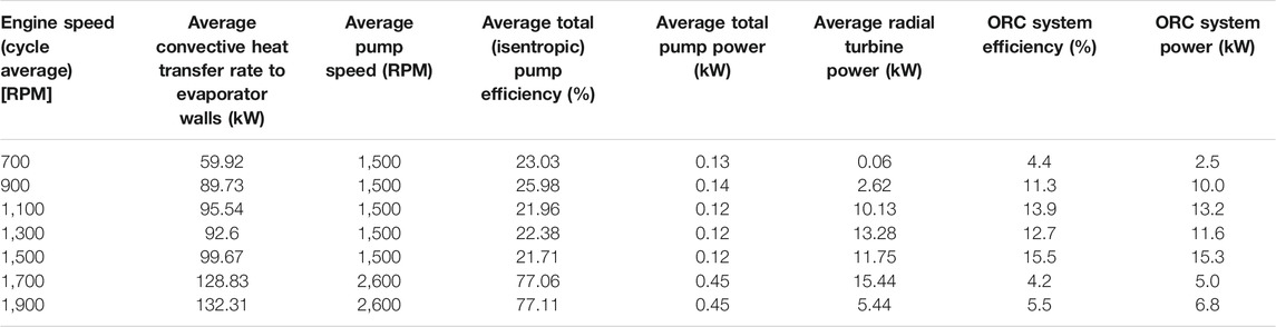
TABLE 2. (A) Performance of ORC system with radial turbine, (B) Stator and rotor optimized values, (C) Stator main geometric and flow angle data and (D) Rotor main geometric and flow angle data.
Axial Turbine Design
Preliminary Blade Design
As described in the methodology, using the in-house MATLAB code, the blade height, mean radius and number of blades were calculated. Using the free vortex equations, the flow angles for the hub, mean and tip radius were preliminary calculated as shown in Figure 6. A physical representation of the angles are shown in Figure 7. The blade height was fixed to 10 mm, the mean radius to 19 mm and the number of blades for stator and rotor were 30 and 15, respectively. The preliminary design parameters of the stator blades are shown in Table 3 and of the rotor in Table 4. It was noticed that the blade angles changed from hub to tip radius due to the application of the free vortex design as it reduces the losses produced by vortices at the profiles of the blades.
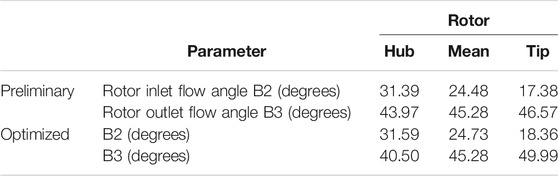
TABLE 3. Rotor main geometric and flow angle data.
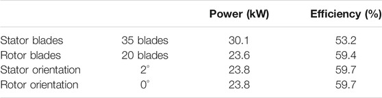
TABLE 4. Stator and rotor optimized values.
The free vortex design produced twisted blades as observed from the values of the angles at different radius. The values for angles A1, A2, and B2 reduce while moving from the hub, to the mean, to the tip. The blades are more twisted at the hub section and then straightened out. However, the angle B3 increases from hub to tip resulting in a more cambered profile.
Turbine Optimization
Following the preliminary blade design. The blades were optimized for the ORC operating conditions. Table 5 presents the final values for each parameter. The first two columns show the new number of blades and orientation. The last two columns show the effect of the varied parameters on the generated power and efficiency. The final values of the geometric paraments, after the optimization, are shown in Table 3 for the stator and in Table 4 for the rotor, while Figure 5A shows two views of the optimised stator and rotor, respectively.
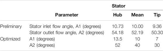
TABLE 5. Stator main geometric and flow angle data.
The final outcomes after the optimization process were:
• Power output—23.7 kW
• Efficiency—66.3%
Once the individual elements and overall performance of the system were compared the next step was to calculate the reduction of BSFC of the engine. To illustrate the reduction in the BSFC of the engine, the BSFC maps (without and with ORC) were plotted in Figures 11B–D, respectively.
There was a significant reduction in the BSFC when the ORC system was integrated with the engine. The reduction is illustrated with another map showing a range from 2% up to 20% in Figure 11.
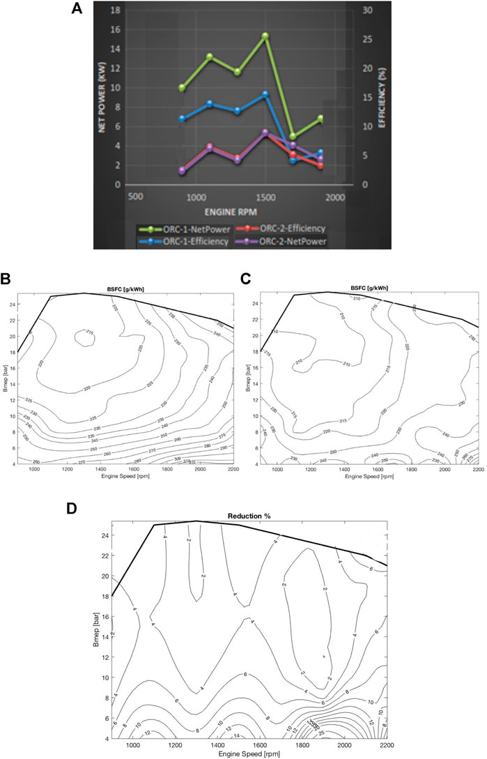
FIGURE 11. (A) Comparison of ORC systems, (B) BSFC map without and (C) with ORC system; (D) percentage of BSFC reduction with ORC installed on modelled HDD engine.
Drive Cycle Comparative Performance
Finally, a simulation of the optimized ORC system was performed under different drive cycles. The drive cycle is a tool to assess fuel consumption and pollutant emissions of a vehicle with several drive cycles considered for this study as discussed in Drive cycles. However, for the purpose of this work, only the fuel consumption was evaluated. Fuel consumption without and with the modelled ORC WHR system was compared. The results confirmed what was discussed in the literature review, the ORC system helped reduce the fuel consumption in a heavy-duty vehicle. The fuel consumption in litres per 100 km is presented in Figure 12 for various drive cycles.
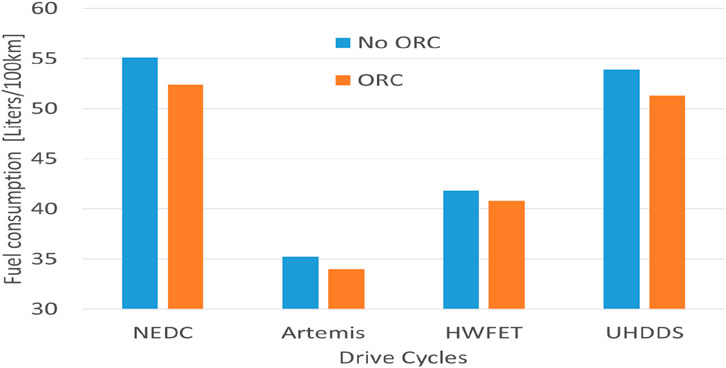
FIGURE 12. Fuel consumption for comparison between ORC and non-ORC cases for the four drive cycles.
The overall percentage of reduction is shown in Table 6. The highest values of fuel consumption were found in the NEDC and the UHDDS as these cycles generally involve more dynamic driving profiles. In these cycles, the ORC could recover more energy and, therefore, produce a higher decrement of fuel consumed.

TABLE 6. Drive cycle results.
The fuel consumption was found to be lower in the Artemis and HWFET cycles, as the profiles were less aggressive. In addition, as the engine was operating in the area where most of the energy from the fuel is utilized there was not as much energy available to be recovered by the ORC. Thus, the decrease in the consumption was lower, as expected.
The savings in terms of fuel consumption calculated in this work, ranged from 2.5 to 5%. These values are well in accordance to the typical experimental and theoretical values of 2–8% reported in the literature (Xu, et al., 2019). However, these values were far lower from the maximum theoretical 10% decrement reported in literature (Alshammari, et al., 2018a). Nevertheless, the results of this work were satisfactory as they proved that the turbine designed for the ORC coupled to the engine would reduce the consumption of fuel.
Conclusion
The aim of this work was to design an axial turbine for an organic Rankine cycle (ORC) system for waste-heat recovery (WHR) from a heavy-duty diesel engine. This technology has attracted significant research interest in recent years as, arguably, the premier short-to-medium term WHR solution in such applications and among technologies that have not yet found widespread production and use. This solution aims to reduce the fuel consumption of the engine by recovering energy from the heat wasted in the exhaust system, and by converting this to electricity or directly into mechanical power that can be used to displace vehicle demands, and therefore the fuel necessary to cover these demands.
In this study, an axial turbine expander design was proposed and improved by using CFD. Moreover, a method to perform preliminary blade calculations was described. Additionally, a model of the heavy-duty truck engine was implemented in GT-Power as well as that of the ORC system modelled for both radial and axial expanders, for comparison purposes.
It was found that when an axial turbine is implemented within an ORC system model coupled to the engine considered in this work, this resulted in a fuel consumption reduction in the range of 2–10% reaching slightly higher values at between 1,200 and 1,600 rpm. Furthermore, it was shown that the axial turbine improved the fuel economy of the vehicle in comparison to the radial turbine by up to 13% at deisgn point. In addition, satisfactory drive cycle tests were performed to simulate real conditions showing a maximum fuel consumption reduction of 5.0% for the obsolete New European Driving Cycle (NEDC), and 4.8% for the much more relevant HDUDDS.
Data Availability Statement
The datasets presented in this article are not readily available because of commercial reasons. Requests to access the datasets should be directed to Brunel University YS5wZXN5cmlkaXNAYnJ1bmVsLmFjLnVr.
Author Contributions
JS was the research student who conducted the simulations. AP was the principal supervisor of the work. PS was assistant supervisor and engine modelling expert, who, also, drafted the results into paper form. PN provided CFD expertise for the simulation and draft checking. CM and MD provided ORC expertise and draft writing and checking.
Conflict of Interest
The authors declare that the research was conducted in the absence of any commercial or financial relationships that could be construed as a potential conflict of interest.
References
Alshammari, F., Karvountzis-Kontakiotis, A., and Pesyridis, A. (2018a). Effect of Radial Turbo-Expander Design on Off-Highway Vehicle Organic Rankine Cycle System Efficiency. Int. J. Powertrains. 7 (Nos. 1/2/3), 72–93. doi:10.1504/ijpt.2018.090364
Alshammari, F., Usman, M., and Pesyridis, A. (2018b). Expanders for Organic Rankine Cycle Technology. in Organic Rankine Cycle Technology for Heat Recovery. London, UK: InTechOpen. 978-1-78984-348-4. doi:10.5772/intechopen.78720
Andwari, A. M., Pesiridis, A., Esfahanian, V., Salavati-Zadeh, A., Karvountzis-Kontakiotis, A., and Muralidharan, V. A. (2017). A Comparative Study of the Effect of Turbocompounding and Orc Waste Heat Recovery Systems on the Performance of a Turbocharged Heavy-Duty Diesel Engine. Energies. 10, 1087. doi:10.3390/en10081087
Capata, R., and Hernandez, G. (2014). Preliminary Design and Simulation of a Turbo Expander for Small Rated Power Organic Rankine Cycle (ORC). Energies 7 (11), 7067–7093. doi:10.3390/en7117067
Chatzopoulou, M. A., Simpson, M., Sapin, P., and Markides, C. N. (2019). Off-design Optimisation of Organic Rankine Cycle (ORC) Engines with Piston Expanders for Medium-Scale Combined Heat and Power Applications. Appl. Energ. 238, 1211–1236. doi:10.1016/j.apenergy.2018.12.086
Chen, H., Goswami, D., and Stefanakos, E. (2010). A Review of Thermodynamic Cycles and Working Fluids for the Conversion of Low-Grade Heat. Renew. Sustainable Energ. Rev. 3 (35), 3059–3067. doi:10.1016/j.rser.2010.07.006
Datla, B. V., and Brasz, J. J. (2014). “Comparing R1233zd and R245fa for Low Temperature ORC”, in International Refrigeration and Air Conditioning Conference. Paper 1524.
Cipollone, R., Di Battista, D., Perosino, A., and Bettoja, F. (2016). Waste Heat Recovery by an Organic Rankine Cycle for Heavy Duty Vehicles. SAE Tech. Pap. 01.
Di Battista, D., Mauriello, M., and Cipollone, R. (2015). Effects of an ORC Based Heat Recovery System on the Performances of a Diesel Engine. SAE Tech. Pap. 01.
Eichler, K., Jeihouni, Y., and Ritterskamp, C. (2015). Fuel Economy Benefits for Commercial Diesel Engines with Waste Heat Recovery. SAE Tech. Pap. 01.
Honeywell, (2010). Working Fluid Development for HT Heat Pumps and ORC Systems. Honeywell: Chillventa.
Hopman, U. (2004). Diesel Engine Waste Heat Recovery Utilizing Electric Turbocompound Technology. San Diego, DEER Conference.
Jeihouni, Y., Eichler, K., and Franke, M. (2016). Lower Emissions in Commercial Diesel Engines through Waste Heat Recovery. SAE Technical Paper 2016-01-8084. doi:10.4271/2016-01-8084
Johnson, C. (2007). Automotive Engine - Physics and Mechanics. [Online] Available at: http://www.mb-soft.com/public2/engine.html (Accessed July 25, 2020).
Karvountzis-Kontakiotis, A., Alshammari, F., Pesiridis, A., Franchetti, B., Pesmazoglou, I., and Tocci, L. (2016). Variable Geometry Turbine Design for off- Highway Vehicle Organic Rankine Cycle Waste Heat Recovery, 2016. Valencia: THIESEL.
Kulkarni, K., and Sood, A. (2015). Performance Analysis of Organic Rankine Cycle (ORC) for Recovering Waste Heat from a Heavy-Duty Diesel Engine. SAE Technical Paper 2015-26-0037. doi:10.4271/2015-26-0037
Le Brun, N., Simpson, M., Acha, S., Shah, N., and Markides, C. N. (2020). Techno-economic Potential of Low-Temperature, Jacket-Water Heat Recovery from Stationary Internal Combustion Engines with Organic Rankine Cycles: A Cross-Sector Food-Retail Study. Appl. Energ. 274, 115260. doi:10.1016/j.apenergy.2020.115260
Markides, C. N., Guarracino, I., and Mathie, R. (2013). Reciprocating Piston Expanders For Small-Scale ORC Systems. s.L. ASME.
Milkov, N., Evtimov, T., and Punov, P. (2015). Advanced Technologies for Waste Heat Recovery in Internal Combustion Engines. Sofia: Technical University of Sofia.
Moroz, L., Nassar, A., and Joly, C. (2015). Tutorial Session on Design and Evaluation Considerations of Waste Heat Recovery Technologies. Montreal: SoftInWay Incorporated. doi:10.1115/power2015-49439
Moroz, L. (2015). Organic Rankine Cycle For Greener Automotive Engines, s.L. Burlington, MA: SoftInway Incorporated.
Nicolas, R. (2013). The Different Driving Cycles. [Online] Available at: http://www.car-engineer.com/the-different-driving-cycles (Accessed September 2, 2020).
Nouman, J. (2012). Comparative Studies and Analyses of Working Fluids for Organic Rankine Cycles - ORC. Stockholm: KTH Royal Institute of Technology.
Pantaleo, A. M., SimpsonRotolo, M., Distaso, G., Distaso, E., Oyewunmi, O. A., Sapin, P., et al. (2019). Thermoeconomic Optimisation of Small-Scale Organic Rankine Cycle Systems Based on Screw vs. Piston Expander Maps in Waste Heat Recovery Applications. Energ. Convers. Management. 200, 112053. doi:10.1016/j.enconman.2019.112053
Peralez, J., Nadri, M., Dufour, P., Tona, P., and Sciarretta, A. (2017). Organic Rankine Cycle for Vehicles: Control Design and Experimental Results. IEEE Trans. Contr. Syst. Technol. 25 (3), 952–965. doi:10.1109/tcst.2016.2574760
A. Pesiridis (2014). in Automotive Exhaust Emissions and Energy Recovery (New York: Nova Science Publishers, Inc.), 251–263.
Qiu, G. (2012). Selection of Working Fluids for Micro-CHP Systems with ORC. Renewable Energy. 48, 567–570. doi:10.1016/j.renene.2012.06.006
Simpson, M. C., Chatzopoulou, M. A., Oyewunmi, O. A., Le Brun, N., Sapin, P., and Markides, C. N. (2019). Technoeconomic Analysis of Internal Combustion Engine - Organic Rankine Cycle Systems for Combined Heat and Power in Energy-Intensive Buildings. Appl. Energ. 253, 113462. doi:10.1016/j.apenergy.2019.113462
Sprouse, C., and Depcik, C. (2013). Review of Organic Rankine Cycles for Internal Combustion Engine Exhaust Waste Heat Recovery. Appl. Therm. Eng. 51, 711–722. doi:10.1016/j.applthermaleng.2012.10.017
Stobart, R., and Milner, D. (2009). The Potential for Thermo-Electric Regeneration of Energy in Vehicles. SAE Technical Paper 2009-01-1333. doi:10.4271/2009-01-1333
Stobart, R., Wijewardane, A., and Allen, C. (2010). The Potential for Thermo-Electric Devices in Passenger Vehicle Application. SAE Technical Paper 2010-01-0833. doi:10.4271/2010-01-0833
Teng, H., Regner, G., and Cowland, C. (2007). Waste Hear Recovery of Heavy-Duty Diesel Engines by Organic Rankine Cycle Part I: Hybrid Energy System of Diesel and Rankine Engines. SAE Tech. Pap. 01.
Vivian, J., Manente, G., and Lazzaretto, A. (2015). A General Framework to Select Working Fluid and Configuration of ORCs for Low-To-Medium Temperature Heat Sources. Appl. Energ. 156 (005), 727–746. doi:10.1016/j.apenergy.2015.07.005
Wilson, D. E. (1986). The Design of a Low Specific Fuel Consumption Turbocompound Engine. Detroit: SAE Technical Papers. doi:10.4271/860072
Keywords: axial turbine, computational fluid dynamics, drive cycle, heady duty diesel, diesel, organic rankine cycle, waste heat recovery
Citation: Soldado JC, Pesyridis A, Sphicas P, Nikolakopoulos P, Markides CN and Deligant M (2021) Axial Turbo-Expander Design for Organic Rankine Cycle Waste-Heat Recovery With Comparative Heavy-Duty Diesel Engine Drive-Cycle Performance Assessment. Front. Mech. Eng 7:676566. doi: 10.3389/fmech.2021.676566
Received: 05 March 2021; Accepted: 12 May 2021;
Published: 16 June 2021.
Edited by:
Tiegang Fang, North Carolina State University, United StatesReviewed by:
Georgios Mavropoulos, National Technical University of Athens, GreeceBart Somers, Eindhoven University of Technology, Netherlands
Copyright © 2021 Soldado, Pesyridis, Sphicas, Nikolakopoulos, Markides and Deligant. This is an open-access article distributed under the terms of the Creative Commons Attribution License (CC BY). The use, distribution or reproduction in other forums is permitted, provided the original author(s) and the copyright owner(s) are credited and that the original publication in this journal is cited, in accordance with accepted academic practice. No use, distribution or reproduction is permitted which does not comply with these terms.
*Correspondence: Panos Sphicas, cGFub3Muc3BoaWNhc0BnbWFpbC5jb20=