 Céline Noël
 Lennaert Wouters1
 Kristof Paredis
 Umberto Celano
- 1Imec, Leuven, Belgium
- 2Faculty of Science and Technology and MESA + Institute for Nanotechnology, University of Twente, Enschede, Netherlands
The ever-increasing complexity of semiconductor devices requires innovative three-dimensional materials characterization techniques for confined volumes. Multiple atomic force microscopy (AFM)-based methodologies, using a slice-and-measure approach have been proposed to meet this demand. They consist of scanning AFM probes that erode locally the sample’s material at a relatively high load while sensing with the secondary AFM channel, thus accessing in-depth information compared to the standard surface-limited analysis. Nonetheless, the rapid tip apex wear caused by the high forces involved, and the debris accumulation at the tip apex and inside/around the scan area, have been identified as major limitations to the accuracy and repeatability of the existing tomographic AFM sensing methods. Here we explore the use of oil as a suitable medium to overcome some of the issues such as the scan debris accumulation and the removal variability when working in air. We show how the use of oil preserves the tomographic operation while improving the efficiency in material removal for large depth sensing at a reduced debris accumulation. This is reported by comparing the results between air and oil environments, where the removal rate, depth accuracy, and tip-contamination are benchmarked. Finally, we provide the first demonstration of electrical AFM sensing using scanning spreading resistance microscopy (SSRM) in oil.
Introduction
With over 30 years of development, scanning probe microscopy (SPM) has now become an important workhorse for the characterization of devices and materials in the semiconductor industry (Orji et al., 2018). SPM represents a set of techniques capable of measuring a wide variety of physical and electrical parameters at the nm-scale, thus finding a broad application space in process control and failure analysis of the increasingly complex microelectronic devices. The pervasive introduction of three-dimensional (3D) semiconductor architectures has motivated the SPM community to explore tomographic sensing schemes for the analysis of confined volumes. These include the alternation of SPM with ion beam milling, micro blades, and wet chemical etching in combination with atomic force microscopy (AFM) sensing (Mochalov et al., 2017; Magerle, 2000; Spampinato et al., 2020). However, the inherent 2D nature of the SPM sensing mechanism, based on probes directly scanning the specimen surface, poses multiple challenges to the development of a full tomographic SPM sensing method. One popular implementation of tomographic SPM is based on the use of nanoscale abrasive wear for the sub-nm material removal with contact-mode AFM, whereby the probe is scanned at a relatively high pressure (typically 2-3 orders of magnitudes higher than the conventional topographic analysis conditions) to obtain the controlled milling of the surface. This concept has been explored and demonstrated by Xu et al. (2002) who reported on the use of a slice-and-measure approach to alternate cycles of electrical measurements and material removal scans, typically applying GPa pressures at the tip-sample junction, to determine the depth carrier profile of InP-based structures. Later, the same approach has been applied to carbon nanotube-based interconnects by Schulze et al. who successfully extracted a nanotomogram using scanning spreading resistance microscopy (SSRM) (Schulze et al., 2012). For ultra-scaled volumes application, Celano et al. (2014) demonstrated the high potential of SPM nanotomography for filament observation in various types of resistive switching memories using conducting AFM (C-AFM) (Celano et al., 2016; Celano et al., 2017) and refined the methodology to obtain a high control of the removal process (Celano et al., 2018). Recently, various groups have embraced the methodology and extended it with alternative AFM techniques, including photoconductive AFM (pc-AFM) and piezo-response force microscopy (PFM) (Luria et al., 2016; Steffes et al., 2019; Song et al., 2021), among others. At present, this approach is often referred to as tomographic AFM (T-AFM) or scalpel SPM and has been used to visualize tomographic information in confined volumes in a wide range of devices and bulk materials (Song et al., 2021).
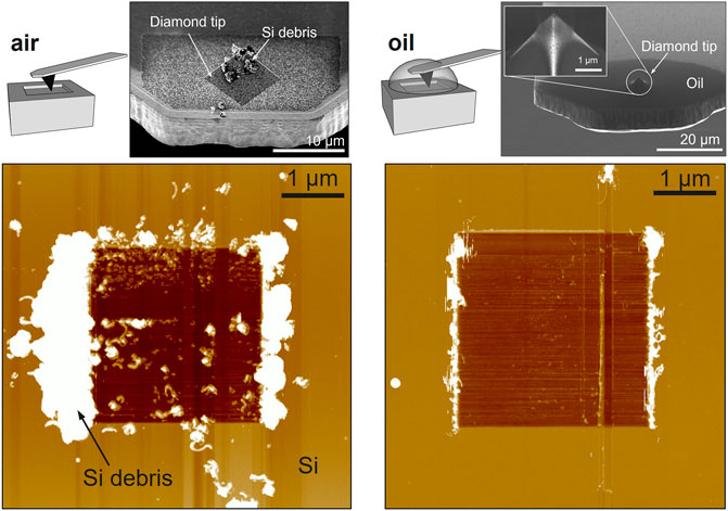
GRAPHICAL ABSTRACT. SEM images of the tips and AFM images of the craters obtained after scanning in air (left) and in oil (right). The debris are efficiently removed from the tip and the crater edges in the oil environment.
Clearly, for this class of techniques, the use of nanoscale abrasive wear for the sub-nm material removal is key to enable accurate and precise tomographic sensing. Therefore, the physics of atomic attrition in sliding single asperities contacts must be addressed to increase the accuracy, repeatability, and resolution of the existing methodology (Chen et al., 2019; Chen et al., 2020).
An overlooked aspect of scalpel SPM is the heavy debris formation and the deposition of this material around the tip apex and in the scan area (Koinkar and Bhushan, 1997; Bhushan and Sundararajan, 1998). As the high-pressure scan is performed, the etched particles pile up, coalesce, and eventually reattach to the surface (Mao et al., 2009). This is directly affecting the measurement quality and repeatability, contributing to the tip wear, and limiting the maximum 3D scan depth (Buckwell et al., 2019). Finally, this can cause multiple reliability issues on the material removal and predictability of tip-induced removal rates, representing some of the main reasons for the limited usability of scalpel SPM.
Here, we explore scalpel SPM performed in an oil environment as a possible solution to overcome the issues of scan debris accumulation while preserving the precise removal rate capability, and electrical AFM modes functionality. It is well known from the macroscopic (Claudin et al., 2010; Lawal et al., 2012; Sharma and Sidhu, 2014) and nanoscopic (Malshe et al., 2005) machining world that cutting fluids such as oils can significantly improve the cutting tool lifetime and flush away debris from the cutting area. Commonly used cutting fluids include oils, oil-water emulsions, aerosols, gels, and gases. In this work, our choice was centered around oils since, first, scalpel SPM is mostly applied for electrical measurements and hence requires an electrically insulating fluid, then, as both the probe and the sample can be constituted of many different metals, the fluid should circumvent oxidation and corrosion, as such oil (e.g., as opposed to water) can be considered an ideal medium for that.
To the authors’ knowledge, oil has not yet been investigated in detail for nanoscopic material removal in scalpel SPM but it has been used in combination with SPM for different purposes. For example, Marti et al. (1987) first proved that AFM can be performed in liquid environments by scanning on a graphite surface covered with paraffin oil. Later, Kelvin Probe Force Microscopy (KPFM) was performed on solid-liquid interfaces (Collins et al., 2014; Collins et al., 2015) and Frequency Modulation-AFM in liquids (Fukuma et al., 2005; Kobayashi et al., 2010). In parallel, the size, shape, and interaction of micron- and nano-sized oil droplets have been studied by different authors (Tabor et al., 2011a; Tabor et al., 2011b; Sánchez et al., 2011; Munz and Mills, 2014; Feng et al., 2019). Here, we report on the use of oil in scalpel SPM demonstrating net improvements 1), in the efficiency of material removal for large depth sensing and 2), for the removal of debris during the measurement, thus improving the sensing accuracy. And 3), we show functionality of electrical AFM modes working in oil, including the first demonstration of SSRM in oil. The paper explains the method, highlights the main performance improvements, and reports the first results of scalpel SPM measurements in oil.
Materials and Methods
Atomic Force Microscopy
All AFM measurements in air and oil are performed using a Dimension Icon PT from Bruker. The material removal step consists of the scanning of a silicon substrate in contact mode at a high force (GPa pressures range).
The probes used for the removal in the present work are boron-doped diamond probes, developed in-house (Hantschel et al., 2009) with a spring constant of 27 N/m, having a nominal length, width, and thickness of 225, 50, and 5 μm, respectively. Diamond probes are key to enable AFM-tip-based milling, as they present a sufficient hardness to scratch away the materials commonly used in semiconductor processing (e.g., Si, SiGe, oxides, nitrides, and metals), as previously demonstrated.
The second step is the examination of the thus-created craters, allowing to assess the debris formation, by scanning over a larger area around the scalpel region. To increase the lateral resolution of this stage, these measurements are made using the Peak Force mode (Xu et al., 2018) with HQ:NSC18/AL BS probes. The results also demonstrate the ability of PF-AFM to provide accurate topography measurements inside an oil droplet.
Scanning Spreading Resistance Microscopy
SSRM measurements were performed using a Bruker Icon-PT system equipped with an SSRM application module in a glovebox under argon atmosphere. The sharp diamond probe is scanned at high force over the biased sample while the 2D resistance and the topography map are recorded.
X-Ray Photoelectron Spectrometry
The measurements were carried out in angle integrated mode using a QUANTES instrument from Physical Electronics at an exit angle of 45°. A 100 microns X-ray spot and a monochromatized photon beam of 1486.6 eV were used.
Scanning Electron Microscopy
SEM images of the probe tips after scanning in air and oil were acquired using a Thermo Fisher Scientific Apreo System.
Results and Discussion
Figure 1A shows the procedure followed in this work to perform scalpel SPM in oil. The oil is collected by engaging the tip into a larger droplet deposited close to a corner of the sample, acting as a reservoir, before moving to a fresh scan area. The oil remaining on the tip apex is enough to guarantee the presence of oil at the tip-sample junction while minimizing possible interference of the oil with the AFM laser reflection from the cantilever that can be induced by the presence of a large droplet (e.g., Figure 1A, oil pick-up step). Here, we select castor bean oil, presenting a higher viscosity compared to the usual inorganic mineral oil and therefore less prone to evaporation from the tip.
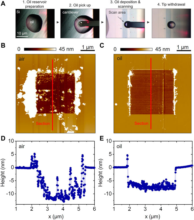
FIGURE 1. (A) Optical microscopy of the main steps to perform scalpel SPM in an oil environment. (B) AFM image of the crater obtained after 2 high-pressure scans in air and (C) in oilusing the same probe tip. Two-dimensional AFM profiles, acquired along the axes labeled “Section” in Fig.1 (A) and (B), are shown in (D) and (E), respectively for the removal in air and oil; note the comparable removal rates obtained in both cases, even though the load force is decreased by a factor of 2 in oil (from ca. 1.2 µN in air to 0.6 µN in oil).
A qualitative comparison of measurements acquired with the same tip in air and oil is provided in Figures 1B,C, respectively. First, in the attempt to compare the impact of the scanning environment on the formation and accumulation of debris, we selected tip-sample load forces that induce a similar material removal rate from the surface as visible by the AFM images and section profiles (Figures 1B–E). A crater with a depth of ca. 10 nm is visible in both images (Figures 1B,C) with a clear accumulation of debris in case of air scanning and limited debris visible in case of scanning in oil. As reported elsewhere, during tomographic AFM debris accumulates around the tip apex and at the crater edges when milling in air (Figure 1B), with a high risk to fall back into the scanned area and impact the quality of the images (Celano et al., 2018; Buckwell et al., 2019). On the contrary, this effect is strongly reduced in oil where the crater edges are sharp and the number of cutting particles is strongly reduced (Figure 1C). Si debris is carried away into the surrounding liquid, avoiding the piling-up at the end of the scan lines and on the tip.
Importantly, beyond the suppression of debris formation, we observe an increased removal rate when scanning in oil as compared to air. In the case of Figure 1, for example, the load force needed to reach depths of approximately 10 nm (see Figures 1D,E), could be reduced by a factor of 2 in oil as compared to air (2 scans at 1.2 µN in air against 2 scans at 0.6 µN in oil). We consistently observe this effect over repeated scans and multiple tips thus confirming that the tip-induced removal is affected by the scanning environment with a proportionality factor that depends on the probe tip but can be estimated in a 2-to-4 times removal rate increase in oil compared to air. This is illustrated in Supplementary Figure S1 (supporting information), where craters of similar depth were obtained in air and in oil with the same probe, but with the load force and number of scans both reduced by a factor of 4 in oil as compared to air.
A quantitative representation of the reduction of the applied force needed to reach a specific removal rate in oil compared to air is also illustrated in Figure 2A, where measurements acquired in both environments and with the same tip allow the direct comparison of the removal rates, as a function of the load force. For each load, the area was scanned 5 times, before measuring the crater depth. The removal rates were then averaged over the 5 scans. In the current dataset, the applied force could be reduced from 1.8 µN in air to 1.3 µN in oil to reach a fixed removal rate of ∼20 nm/scan. At 1.8 µN, the removal rate is increased by a factor of up to ca.1.4 observed in oil compared to air.
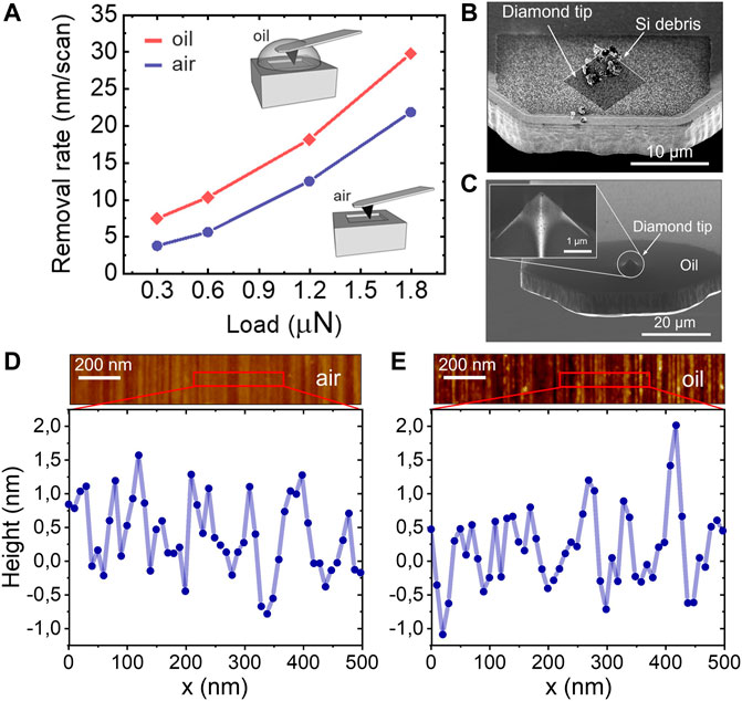
FIGURE 2. (A) Comparison of the removal rates as a function of the applied force for the two environments. SEM images of the tips after scanning in air (B) and oil (C); Individual section profiles lines from AFM are used for the evaluation of the roughness in the craters for air (D) and oil (E).
Higher removal rates at constant load allow enhancing the machining capability, which might be relevant for applications where depth information over a micron or more is crucial, such as material de-layering in failure analysis of integrated circuits or precise machining.
To explain the enhancement in materials removal in oil, we assume that the absence of debris on the surface and the tip apex facilitates a more efficient ploughing action since the tip is scratching a “fresh” area at each scan.
Furthermore, we hypothesize that the presence of oil could favor mechanochemical reactions, and eventually increase the interaction forces between the probe tip and the etched substrate. Other groups reported on such reactions (Milne et al., 2019; Xiao et al., 2019) (e.g., the removal of surface terminal species) that locally modify the surface at the interface between the tip and the sample and affect the material removal rate.
A third explanation involves the potential capillary forces taking place at the tip-droplet interface, thus increasing the removal rate at fixed load force when working in oil. In other words, the presence of oil could increase the effective load force applied on the surface, while keeping the measured cantilever deflection constant.
On the other hand, it would be equally important to guarantee a high control of material removal while decreasing the tip-sample load force, thereby increasing the removal accuracy. While this report does not quantitatively address this aspect, our first experimental data suggest that working in oil does not limit a nm-precise material removal that was previously obtained when working in air (Celano et al., 2018).
Interestingly, the impact of oil is also expressed through a net reduction of the residues sticking to the tip after the material removal. This is reported in Figure 2 where we display SEM images of the tips after scanning in air (b) and oil (c). The corresponding craters are shown in Supplementary Figure S2, where SEM images were acquired in air and AFM images in oil. Again, in air (Supplementary Figure S2A), a significant quantity of debris accumulates in the machined area, while it was washed away by the oil (Supplementary Figure S2B).
Concerning how the oil modifies the interactions between the tip and the sample, Figures 2D,E suggest that the roughness is not affected since similar profiles are found in both environments. Note that to perform the analysis of the surface quality with the highest possible resolution, we have used a fresh high aspect-ratio probe tip in peak force tapping mode.
In parallel, XPS analyses were conducted on Si samples (described in Supplementary Table S1) to look for possible alterations in the surface chemistry. The surface composition of the bare reference Si substrates was compared to Si dipped into hydrogen fluoride (HF), so that the native oxide is removed, then exposed to air or oil for 6 days. The oil was subsequently cleaned off in propanol prior to ultra-high vacuum (UHV). No significant difference in the long-term oxidation behavior can be observed between the sample immersed in oil and in ambient air, indicating that the oil has no negative -or positive-impact on the overall surface oxidation. In a similar test, 10 s vs. 6 days, a slightly lower SiOx/Si ratio for the oil-immersed sample can be observed. This might indicate that the initial oxidation is somewhat slowed down in the presence of oil. The XPS results are summarized in Supplementary Figure S3.
Finally, in the last section, we assess the feasibility of one common electrical-AFM method, namely scanning spreading resistance microscopy (SSRM), in oil. Figure 3 shows the comparison between SSRM images (Figures 3A,C) and profiles averaged over a 1 µm-wide cross-section (Figures 3B,D) obtained on a standard p-type Si calibration structure commonly used for SSRM calibration (Clarysse et al., 1998). The scan line density, i.e., the number of lines within the scanned area, was increased from 256 to 1008 pixels during 3 scans. The measurements were performed with the same boron-doped diamond probe and at the same force of ca. 3.6 µN.
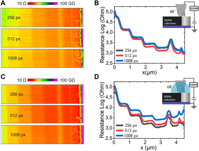
FIGURE 3. SSRM resistance maps (A and C) and the corresponding profiles (B and D), acquired on calibration staircase structures in air (upper row) and in oil (lower row), for three different scan line densities. Averaged SSRM profile lines are extracted for comparison in air (B) and oil (D).
Interestingly, both environments yield good quality SSRM measurements as visible from the clear appearance of all doping levels contained in the calibration structure. These results constitute, to our knowledge, the first feasibility study of SSRM measurements in oil. Note, to minimize any tip-induced variation in the study, we have performed the measurement using the same probe tip. For information purposes, the noise levels, considered only on this dataset, and therefore only consistent for this particular tip, are comparable in both environments. However, more statistics are needed to draw general conclusions. Upcoming work should support these encouraging preliminary results. Our hypothesis is that the lack of fast surface reoxidation can be a possible source of noise reduction by reducing the overall tip-sample contact resistance, allowing to obtain a higher sensitivity to the spreading resistance term (β-Sn phase), leading to higher lateral and depth resolutions.
The use of oil could allow decreasing the load force applied on the tip while the higher removal rate would limit damage accumulation.
Conclusion
In summary, we studied the role of single asperity tip contacts operating in oil and at high-pressure scan conditions for application in scalpel SPM. Our work demonstrates, for the first time, the feasibility of electrical AFM modes such as SSRM, in an oil environment. Beyond this we observe performance improvements that can be summarized in four points:
- The quantity of scanning debris at the crater edges and sticking to the probe tip is dramatically reduced, thus improving the sensing accuracy in the area of interest.
- The material removal rate capability, and therefore the maximum 3D scan depth of scalpel SPM is extended. Removal rates up to twenty times higher were recorded in oil compared to results obtained in the air with the same tip.
- The feasibility of scanning spreading resistance microscopy in oil, with comparable (or improved) noise as in air, was demonstrated for the first time.
Given the increasing interest in scalpel-based three-dimensional scanning probe microscopy, we believe that the use of oil is going to be more and more applied to 3D SPM analyses, on a wide range of hard materials, relevant for the semiconductor industry, such as silicon, oxides, and metals.
Data Availability Statement
The original contributions presented in the study are included in the article/Supplementary Material, further inquiries can be directed to the corresponding author.
Author Contributions
Conceptualization, KP and TH; Analyses, CN, LW, and TH; Writing—Original Draft Preparation, CN, UC, and TH; Writing—Review and Editing, all co-authors.
Conflict of Interest
The authors declare that the research was conducted in the absence of any commercial or financial relationships that could be construed as a potential conflict of interest.
Publisher’s Note
All claims expressed in this article are solely those of the authors and do not necessarily represent those of their affiliated organizations, or those of the publisher, the editors and the reviewers. Any product that may be evaluated in this article, or claim that may be made by its manufacturer, is not guaranteed or endorsed by the publisher.
Acknowledgments
The authors gratefully acknowledge Thierry Conard for assistance with XPS measurements and Stefanie Sergeant for Peak-Force AFM measurements.
Supplementary Material
The Supplementary Material for this article can be found online at: https://www.frontiersin.org/articles/10.3389/fmech.2021.797962/full#supplementary-material
References
Bhushan, B., and Sundararajan, S. (1998). Micro/nanoscale Friction and Wear Mechanisms of Thin Films Using Atomic Force and Friction Force Microscopy. Acta Materialia 46, 3793–3804. doi:10.1016/s1359-6454(98)00062-7
Buckwell, M., Ng, W. H., Hudziak, S., Mehonic, A., Lanza, M., and Kenyon, A. J. (2019). Improving the Consistency of Nanoscale Etching for Atomic Force Microscopy Tomography Applications. Front. Mater. 6, 203. doi:10.3389/fmats.2019.00203
Celano, U., Gastaldi, C., Govoreanu, B., Richard, O., Bender, H., Goux, L., et al. (2017). Evidences of Areal Switching in Vacancy-Modulated Conductive Oxide (VMCO) Memory. Microelectronic Eng. 178, 122–124. doi:10.1016/j.mee.2017.04.046
Celano, U., Giammaria, G., Goux, L., Belmonte, A., Jurczak, M., and Vandervorst, W. (2016). Nanoscopic Structural Rearrangements of the Cu-Filament in Conductive-Bridge Memories. Nanoscale 8, 13915–13923. doi:10.1039/c5nr08735j
Celano, U., Goux, L., Opsomer, K., Iapichino, M., Belmonte, A., Franquet, A., et al. (2014). Scanning Probe Microscopy as a Scalpel to Probe Filament Formation in Conductive Bridging Memory Devices. Microelectronic Eng. 120, 67–70. doi:10.1016/j.mee.2013.06.001
Celano, U., Hsia, F.-C., Vanhaeren, D., Paredis, K., Nordling, T. E. M., Buijnsters, J. G., et al. (2018). Mesoscopic Physical Removal of Material Using Sliding Nano-diamond Contacts. Sci. Rep. 8, 2994. doi:10.1038/s41598-018-21171-w
Chen, R., Vishnubhotla, S. B., Jacobs, T. D. B., and Martini, A. (2019). Simulations of the Effect of an Oxide on Contact Area Measurements from Conductive Atomic Force Microscopy. Nanoscale 11, 1029–1036. doi:10.1039/c8nr08605b
Chen, R., Vishnubhotla, S. B., Khanal, S. R., Jacobs, T. D. B., and Martini, A. (2020). Quantifying the Pressure-Dependence of Work of Adhesion in Silicon-diamond Contacts. Appl. Phys. Lett. 116, 051602. doi:10.1063/1.5127533
Clarysse, T., Caymax, M, Wolf, P. D, Trenkler, T, and Vandervorst, W (1998). Epitaxial Staircase Structure for the Calibration of Electrical Characterization Techniques. J. Vac. Sci. Technol. B 16, 394. doi:10.1116/1.589820
Claudin, C., Mondelin, A., Rech, J., and Fromentin, G. (2010). Effects of a Straight Oil on Friction at the Tool-Workmaterial Interface in Machining. Int. J. Machine Tools Manufacture 50, 681–688. doi:10.1016/j.ijmachtools.2010.04.013
Collins, L., Jesse, S., Kilpatrick, J. I., Tselev, A., Okatan, M. B., Kalinin, S. V., et al. (2015). Kelvin Probe Force Microscopy in Liquid Using Electrochemical Force Microscopy. Beilstein J. Nanotechnol. 6, 201–214. doi:10.3762/bjnano.6.19
Collins, L., Kilpatrick, J. I., Vlassiouk, I. V., Tselev, A., Weber, S. A. L., Jesse, S., et al. (2014). Dual Harmonic Kelvin Probe Force Microscopy at the Graphene-Liquid Interface. Appl. Phys. Lett. 104, 133103. doi:10.1063/1.4870074
Feng, L., Manica, R., Grundy, J. S., and Liu, Q. (2019). Unraveling Interaction Mechanisms between Molybdenite and a Dodecane Oil Droplet Using Atomic Force Microscopy. Langmuir 35, 6024–6031. doi:10.1021/acs.langmuir.9b00203
Fukuma, T., Kobayashi, K., Matsushige, K., and Yamada, H. (2005). True Atomic Resolution in Liquid by Frequency-Modulation Atomic Force Microscopy. Appl. Phys. Lett. 87, 034101. doi:10.1063/1.1999856
Hantschel, T., Demeulemeester, C., Eyben, P., Schulz, V., Richard, O., Bender, H., et al. (2009). Conductive diamond Tips with Sub-nanometer Electrical Resolution for Characterization of Nanoelectronics Device Structures. Phys. Stat. Sol. (A) 206, 2077–2081. doi:10.1002/pssa.200982212
Kobayashi, N., Asakawa, H., and Fukuma, T. (2010). Nanoscale Potential Measurements in Liquid by Frequency Modulation Atomic Force Microscopy. Rev. Scientific Instr. 81, 123705. doi:10.1063/1.3514148
Koinkar, V. N., and Bhushan, B. (1997). Scanning and Transmission Electron Microscopies of Single-crystal Silicon Microworn/machined Using Atomic Force Microscopy. J. Mater. Res. 12, 3219–3224. doi:10.1557/jmr.1997.0421
Lawal, S. A., Choudhury, I. A., and Nukman, Y. (2012). Application of Vegetable Oil-Based Metalworking Fluids in Machining Ferrous Metals-A Review. Int. J. Machine Tools Manufacture 52, 1–12. doi:10.1016/j.ijmachtools.2011.09.003
Luria, J., Kutes, Y., Moore, A., Zhang, L., Stach, E. A., and Huey, B. D. (2016). Charge Transport in CdTe Solar Cells Revealed by Conductive Tomographic Atomic Force Microscopy. Nat. Energ. 1, 16150. doi:10.1038/nenergy.2016.150
Malshe, A. P., Virwani, K., Rajurkar, K. P., and Deshpande, D. (2005). Investigation of Nanoscale Electro Machining (Nano-EM) in Dielectric Oil. CIRP Ann. 54, 175–178. doi:10.1016/s0007-8506(07)60077-8
Mao, Y.-T., Kuo, K.-C., Tseng, C.-E., Huang, J.-Y., Lai, Y.-C., Yen, J.-Y., et al. (2009). Research on Three Dimensional Machining Effects Using Atomic Force Microscope. Rev. Scientific Instr. 80, 065105. doi:10.1063/1.3125623
Marti, O., Drake, B., and Hansma, P. K. (1987). Atomic Force Microscopy of Liquid‐covered Surfaces: Atomic Resolution Images. Appl. Phys. Lett. 51, 484–486. doi:10.1063/1.98374
Milne, Z. B., Bernal, R. A., and Carpick, R. W. (2019). Sliding History-dependent Adhesion of Nanoscale Silicon Contacts Revealed by In Situ Transmission Electron Microscopy. Langmuir 35, 15628–15638. doi:10.1021/acs.langmuir.9b02029
Mochalov, K. E., Chistyakov, A. A., Solovyeva, D. O., Mezin, A. V., Oleinikov, V. A., Vaskan, I. S., et al. (2017). An Instrumental Approach to Combining Confocal Microspectroscopy and 3D Scanning Probe Nanotomography. Ultramicroscopy 182, 118–123. doi:10.1016/j.ultramic.2017.06.022
Munz, M., and Mills, T. (2014). Size Dependence of Shape and Stiffness of Single Sessile Oil Nanodroplets as Measured by Atomic Force Microscopy. Langmuir 30, 4243–4252. doi:10.1021/la5001446
Orji, N. G., Badaroglu, M., Barnes, B. M., Beitia, C., Bunday, B. D., Celano, U., et al. (2018). Metrology for the Next Generation of Semiconductor Devices. Nat. Electron. 1, 532–547. doi:10.1038/s41928-018-0150-9
Sánchez, M. C., Franco, J. M, Valencia, C., Gallegos, C., and Urchegui, R., (2011). Atomic Force Microscopy and Thermo-Rheological Characterisation of Lubricating Greases. Tribol. Lett. 41, 463–470. doi:10.1007/s11249-010-9734-x
Schulze, A., Hantschel, T., Dathe, A., Eyben, P., Ke, X., and Vandervorst, W. (2012). Electrical Tomography Using Atomic Force Microscopy and its Application towards Carbon Nanotube-Based Interconnects. Nanotechnology 23, 305707. doi:10.1088/0957-4484/23/30/305707
Sharma, J., and Sidhu, B. S. (2014). Investigation of Effects of Dry and Near Dry Machining on AISI D2 Steel Using Vegetable Oil. J. Clean. Prod. 66, 619–623. doi:10.1016/j.jclepro.2013.11.042
Song, J., Zhou, Y., and Huey, B. D. (2021). 3D Structure-Property Correlations of Electronic and Energy Materials by Tomographic Atomic Force Microscopy. Appl. Phys. Lett. 118, 080501. doi:10.1063/5.0040984
Spampinato, V., Dialameh, M., Franquet, A., Fleischmann, C., Conard, T., van der Heide, P., et al. (2020). A Correlative ToF-SIMS/SPM Methodology for Probing 3D Devices. Anal. Chem. 92, 11413–11419. doi:10.1021/acs.analchem.0c02406
Steffes, J. J., Ristau, R. A., Ramesh, R., and Huey, B. D. (2019). Thickness Scaling of Ferroelectricity in BiFeO3 by Tomographic Atomic Force Microscopy. Proc. Natl. Acad. Sci. USA 116, 2413–2418. doi:10.1073/pnas.1806074116
Tabor, R. F., Lockie, H., Mair, D., Manica, R., Chan, D. Y. C., Grieser, F., et al. (2011). Combined AFM−Confocal Microscopy of Oil Droplets: Absolute Separations and Forces in Nanofilms. J. Phys. Chem. Lett. 2, 961–965. doi:10.1021/jz2003606
Tabor, R. F., Wu, C., Lockie, H., Manica, R., Chan, D. Y. C., Grieser, F., et al. (2011). Homo- and Hetero-Interactions between Air Bubbles and Oil Droplets Measured by Atomic Force Microscopy. Soft Matter 7, 8977. doi:10.1039/c1sm06006f
Xiao, C., Xin, X., He, X., Wang, H., Chen, L., Kim, S. H., et al. (2019). Surface Structure Dependence of Mechanochemical Etching: Scanning Probe-Based Nanolithography Study on Si(100), Si(110), and Si(111). ACS Appl. Mater. Inter. 11, 20583–20588. doi:10.1021/acsami.9b00133
Xu, K., Sun, W., Shao, Y., Wei, F., Zhang, X., Wang, W., et al. (2018). Recent Development of PeakForce Tapping Mode Atomic Force Microscopy and its Applications on Nanoscience. Nanotechnol. Rev. 7, 605–621. doi:10.1515/ntrev-2018-0086
Keywords: SPM, oil, nanotomography, scalpel SPM, diamond tip, debris removal
Citation: Noël C, Wouters L, Paredis K, Celano U and Hantschel T (2021) Oil as an Enabler for Efficient Materials Removal in Three-Dimensional Scanning Probe Microscopy Applications. Front. Mech. Eng 7:797962. doi: 10.3389/fmech.2021.797962
Received: 19 October 2021; Accepted: 02 December 2021;
Published: 21 December 2021.
Edited by:
Mark Gee, National Physical Laboratory, United KingdomReviewed by:
Andras Vernes, Vienna University of Technology, AustriaFrancesc Perez-Murano, Spanish National Research Council (CSIC), Spain
Copyright © 2021 Noël, Wouters, Paredis, Celano and Hantschel. This is an open-access article distributed under the terms of the Creative Commons Attribution License (CC BY). The use, distribution or reproduction in other forums is permitted, provided the original author(s) and the copyright owner(s) are credited and that the original publication in this journal is cited, in accordance with accepted academic practice. No use, distribution or reproduction is permitted which does not comply with these terms.
*Correspondence: Céline Noël, Y2VsaW5lLm5vZWxAaW1lYy5iZQ==