 Daniel Ketemaw
 Solomon Seid
- 1Faculty of Manufacturing Engineering, Hawassa Institute of Technology, Hawassa, Ethiopia
- 2Center for Research and Development, College of Engineering, Defense University, Bishoftu, Ethiopia
Urban vehicles (like tricycle and bicycle vehicle) are made to handle issues with traffic, air pollution, energy use, and parking restrictions in big cities. However, they are more susceptible to rollovers and stability problems because they are smaller and narrower than normal cars. Now a day, Vehicle manufacturers place a lot of emphasis on the dynamic stability of their products. As a result, develop dynamic model to predict and detect the risk of rollover and designing a controller to reduce it in a delta type configuration of tricycle vehicle is the major concern of this paper. On the basis of a two degree of freedom (2-DOF) bicycle model, develop rollover dynamics, and design state observer for sideslip angle, sliding mode and fuzzy logic controller are the major concern of this paper. The suggested rollover index (RI) accuracy has been evaluated by simulation using a high-fidelity CarSim. The performance analysis to determine the effectiveness of thus proposed controller is conducted using MATLAB/Simulink integrated with the Carsim software. Simulation results with three scenarios are shown with and without the control system. The outcome of the simulation demonstrated that fuzzy sliding mode controller (FSMC) and a fuzzy logic controller can reduces the chance of a vehicle rolling over accident.
1 Introduction
The word “roll” refers to the weight shifting sideways in a vehicle from left to right or vice versa. Depending on how sharply the car steers and how quickly it is moving, this shift will happen immediately. High-speed driving and poor balance control during cornering result in the most severe crashes and accidents. A significant safety concern for a large class of cars is rollover. Serious and fatal injuries are disproportionately caused by it. The majority of fatalities in passenger automobile accidents-nearly 33%-were caused by rollovers (Yoon et al., 2007). There is currently a problem because of the increase in car traffic and the extreme levels of pollution in cities (Ataei, 2017). The use of smaller vehicles is an alternative to preventing such issues, primarily because they are lightweight, narrow in design, fuel-efficient, easy to drive and park (Ojolo et al., 2020). Skids can be stopped using a technology called vehicle stability control. By stopping one or more wheels to fix the condition, Roll Stability Control provides improved rollover safety. The goal is to make it possible for a driver to keep control of a car during quick, abrupt, or rapid changes in direction. The main flaw that prevents these automobiles from being utilized more widely is their lack of corner stability (of roll stability) and vehicle stability due to their short and narrow shape, as well as the fact that they only have one wheel at the front as opposed to traditional four-wheel vehicles (Rodríguez-Licea, 2021).
The condition for tricycle vehicle’s capacity to maintain its upright position in the event of a rollover is given by (Azim et al., 2015)
Where, b is vehicle track width, h is height of center of gravity of vehicle, L is wheel base of vehicle,
It is demonstrated in (IEEE Centro Occidente Section and Institute of Electrical and Electronics Engineers, 2018) how to obtain and validate a new tricycle rollover index and how effective it is to anticipate and identify risk even statically. Additionally, a proportional controller for reducing rollover risk and a stability study based on Laplace equations are described. Simulations demonstrate how the differential braking approach can effectively prevent or lessen rollover. However, this Lyapunov based proportional controller demonstrates that it is resilient to alterations in parameters like the center of gravity (COG) in a specified range only. This paper spur on more three-wheeled vehicle safety research, particularly in the area of robust nonlinear controllers.
The most pertinent exploration about the lateral stability tendency in a three-wheeled vehicle was reported by the authors in (Ebhota et al., 2015). For stability assessments and solid modeling, Solid Works software was utilized. For the tricycle model, the weight distribution in the vehicle, the lateral acceleration, the static margin, and the understeer gradient were calculated using the mass, COG height, track length, and longitudinal length (wheelbase) measurement. The findings indicate that the tricycle model is unstable when traveling above the crucial speed because it responds to side loads by yawing about its COG. Additionally, the authors do not offer a lateral acceleration prevention technique or a dynamic verification of the risk assessment methodology.
Modeling and control algorithms for a three-wheeled mobile robot that can drive and steer using its front wheels have been described in (Pandey et al., 2017). The authors described an electric tricycle vehicle’s model of the system for autonomous velocity control and trajectory control. A PID controller is utilized, and software simulations are shown, but it is assumed that the trike can follow any trajectory because a curved path is determined. However, even though the trike can follow any trajectory, lateral stability is not guaranteed, meaning still susceptible to a rollover. In (Zandieh, 2014), the author examines the impact of implementing camber angle on the handling, lateral stability, and ride conveniency of a tricycle vehicle with a tadpole type configuration. Calculations are made in accordance with the impact of implementing active camber angles on the relevant stability parameter, skidding as well as rollover acceleration threshold. By determining the appropriate transfer functions and then graphing the associated Bode diagrams, the influence of camber angle at various vehicle speeds on the yaw rate was examined in order to determine how the vehicle handled. Vehicle rollover and slide may occur on different roadways and at various camber angles. In order to regulate this model problem, the authors do not suggest any particular control mechanism.
In (Yoon et al., 2007) a roll dynamics phase plane analysis creates a rollover index that predicts an upcoming rollover. A direct yaw control technique is used to create a differential brake control legislation. The rollover index serves as the basis for calculating the vehicle stability control (VSC) threshold. It has been demonstrated that the suggested rollover index can serve as a reliable indicator of the risk of a rollover and that the rollover index-based VSC scheme can lower that risk. A sliding mode controller (SMC) was created to produce the desired yaw moment based on the discrepancy between yaw rates of the target and the measured values. However, those author focuses on four wheeled vehicles rather than three wheeled ones while presenting the control methods. In this thesis a dynamic model and RI for a Delta type of tricycle vehicle will be demonstrated. The mathematical lateral dynamic model is verified in the case of a closed loop and open loop situation with CarSim and Simulink environments. Later, a rollover mitigation and prevention controller (SMC) using a rear differential braking system as an actuator developed, and through MATLAB/Simulink and carsim controller performance validated. Finally, illustrative simulations presented to study the performance of the controller on MATLAB/Simulink.
2 Vehicle dynamics
2.1 Three wheeled vehicle dynamics
An adequate vehicle model must be derived in order to effectively characterize the vehicle dynamics. The model of 3-wheeled vehicle (TWV) derived from this is the widely single-track design, also referred to as the bicycle model (Anders, 2006), (Ling, 2006).
The geometrical relationships that govern the system provide the basis for the equations of motion.
The front and back wheels’ slip angles are shown in Figure 1 expressed by
Where,
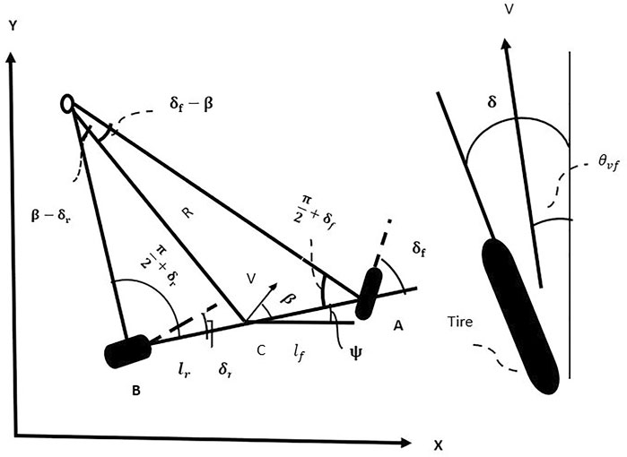
FIGURE 1. Kinematics of lateral vehicle motion.
Following that, the notation
As seen in Figure 2 , a 2-DOF “bicycle” model of the vehicle is taken into consideration. The “vehicle’s lateral position (y) and yaw angle (
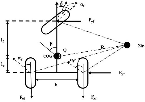
FIGURE 2. Tricycle model approximation.
The following forces are located around the tricycle vehicle’s center of gravity (Licea et al., 2018):
In the front and back wheels, there are lateral forces and longitudinal forces that interact as follows:
The lateral tyre force of a tyre at low slip-angles is found to be proportional to the slip-angle through experimental research. (Zhang et al., 2009), (Chen, 1999).
The equation for the vehicle’s lateral tire forces is determined by substituting from Equation (Eq. 3) into Equation (Eq. 6).
where
Newton’s second law can be used to generate the laws of motion. and/or balancing the torque around the z-axis (vertical axis) as shown in Figure 2 above results in,
Were, the acceleration of the car’s inertia at COG. in the direction of the y axis is given by the symbol
From the figure, the relation
Inserting these all-sub equations into equation (Eq. 8, 9) the lateral and yaw motion formulae are given below along with the assumption of minimal steering wheel angle.
Where
The lateral acceleration can now be represented by,
2.2 Rollover index
It is common knowledge that an unbalanced vertical force on a wheel result in a rollover condition. It is suggested that the new rollover index (RI) for 3-wheeled vehicles be the “normalized difference of the vertical forces at the wheel ground contact” when these forces are equal, there is no danger. “The risk of tipping increases with the absolute value of the rollover index’s proximity to the unit, and the sign denotes which side the risk is presented” (Ataei, 2017).
Where,
In Figure 2, carrying out a torque balance with regard to the point at both the left and right contact locations of the back wheels with the ground, and from right to left:
Substituting those variables, the equation of (Eq. 9), yields
Finally, by replacing the lateral acceleration into the above Equation
2.3 Model validation
This section details the widely used CarSim simulation program’s assessment of the vehicle’s mathematical model and the efficiency of the RI to predict and detect a rollover. CarSim features a very user-friendly interface, the ability to link with MATLAB and HIL systems, and excellent result display. This validation is done by comparing the data obtained by the integration of the mathematical model in MATLAB with that produced by CarSim at steady speeds, double lane changes. According to this study, tipping is the imminent overturn of a vehicle when one of the rear wheels encounters zero vertical force.
All simulations in this part were performed at
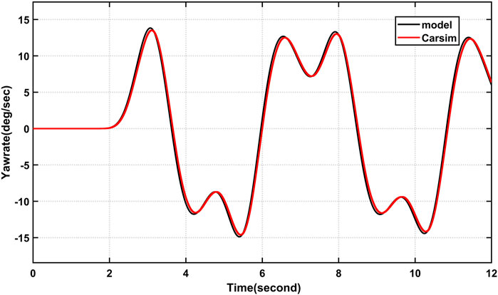
FIGURE 3. A comparison between the tricycle model that has been suggested and CarSim’s yaw rate.
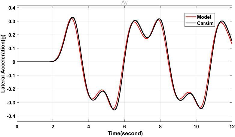
FIGURE 4. Comparison between the tricycle model that has been suggested and CarSim’s lateral acceleration.
2.3.1 Rollover index validation
By contrasting the vertical forces on the rear wheels provided by CarSim with the RI value, the RI value is verified. To put it another way, a low vertical force value in a wheel indicates that it is in serious danger of losing contact with the ground and tipping; in this situation, the absolute value of the RI must be close to 1. The indicator indicates that there is either a risk to the right (RI > 0) or to the left (RI < 0).
Figure 5 maneuver is employed first. Figure 6 shows the vertical forces acting on the rear wheels; these forces have been normalized for easy comparison with the RI (divided by mg). Additionally, the RI value is shown. When making a right turn, a low vertical force in the right rear wheel corresponds to a high vertical force in the left rear wheel. At time t = 5.45 s, the RI is calculated to be roughly 0.69, indicating that there is no danger of rollover during a right turn.
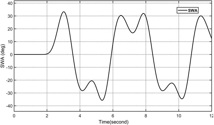
FIGURE 5. Double Lane change manoeuvre.
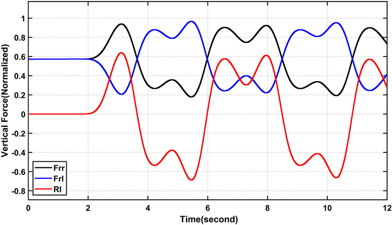
FIGURE 6. Comparison of the RI and the actual (normalized) vertical forces experienced by the back wheels during a typical maneuver without a risk of rollover.
Second, the action seen in Figure 5 is multiplied by 1.35 (135%) and used as the steering input to mimic a risky movement. Thus, the RI is approximately 0.9, indicating a considerable danger of rollover during a left turn. The simulation performed by CarSim at t = 5.47s demonstrates a significant rollover risk. The motion shown in Figure 5 is multiplied by 1.70 (170%) and utilized as the steering input to simulate a rollover maneuver. Figure 7 shows the normalized vertical forces at the back wheels along with the RI value. From time t = 6.25 s onwards, it is evident that a zero vertical force in the left rear tire force signals an oncoming tip, such that the RI exceed 1, indicating that a left turn rollover is likely to happen.
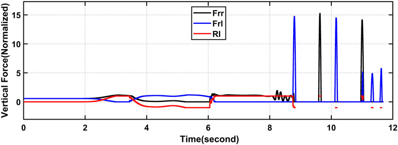
FIGURE 7. Comparison between the RI and the actual (normalized) vertical forces at the rear wheels at an increment of 170% of the maneuver.
3 Control system design
Active roll stability control systems are stability control systems that stop rollover. “Both yaw stability and roll over stability control” may be included in an integrated stability control system. Differential braking systems, which are frequently employed on production vehicles to regulate yaw and roll stability, have received the majority of research attention. “Roll stability control systems” use sensors or measurable states on the vehicle in order to determine whether a rollover is about to occur and whether a corrective action is necessary. If corrective action is necessary, differential braking is employed to make the car slower as well as to cause an understeer that lowers the rate at which the vehicle rolls and/or to rotate the vehicle in the opposite direction to decrease lateral acceleration. Although sensors are capable of measuring both the “sideslip angle and the real yaw rate”, the sideslip angle sensor is too expensive. As a result, the sideslip angle’s value is commonly estimated using the state observer (Zhang et al., 2009). Figure 8 provides a representation of the control design diagram.
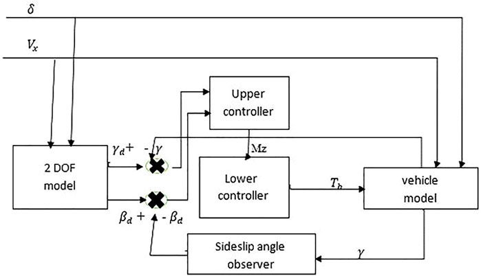
FIGURE 8. Structure of overall control system.
With the help of a sliding mode controller or fuzzy logic controller, an external yaw moment would be calculated. A lower controller then evenly distributes the torque to each wheel in accordance with the necessary yaw moment generated by the above controller.
3.1 Sideslip angle observer
The angle created by the longitudinal direction and the vehicle’s travel direction is known as the sideslip angle. In light of the final state space equation.
Where
“The sideslip angle observer can be created as follows in accordance with the linear control theory” (Chen, 1999)
Where
It receives two inputs (u and y), and as an output it produces an approximated state
If all eigenvalues of (A-LD) are properly assigned, i.e., if (A-LD) < 0 then we can regulate the rate at which e(t) approaches zero or, equivalently, in order for the predicted state to resemble the real state.
L is a “gain matrix” and is defined as
Then L can be calculated as
3.2 Upper controller
3.2.1 Fuzzy sliding mode controller
Sliding mode control is a type of variable structure control where the dynamics of a nonlinear system are altered via the application of a high-frequency switching control. To create a control law, we must first specify the sliding surface that fixes the desired dynamics. There are two steps in this. We first push the system to the surface, after which we must keep it sliding along that surface to reach the phase plane’s origin.
The desired yaw rate and desired side-slip angle for the vehicle can therefore be obtained from (Zhang et al., 2009).
The selection of a sliding surface is the initial stage in designing an SM controller.
where ξ > 0 is the weight coefficient it illustrates the percentage of sideslip angle variance.
Taking the derivative of equation (Eq. 14) yields
Substituting equation (Eq. 7) into equation (Eq. 15), one has
Based on thus Lyapunov function yaw moment control law is designed as
Where
If the switch gain is maintained at a constant value, large disturbances may cause the yawing moment of output to exhibit significant chatter. As a result, this study incorporates fuzzy theory to control the gain to quiet down the chatter, and to improve the performance of sliding mode controller. The switch gain, which is denoted by the symbol
IF
IF
IF
IF
IF
IF
IF
3.2.2 Fuzzy-logic controller
Fuzzy logic control is a nonlinear control technique that works well to manage the uncertainties and nonlinearities present in complicated control systems. In this research, a fuzzy logic controller that seeks to make the real yaw rate and sideslip angle trace their target values in order to mitigate the rollover risk of delta-type tricycle vehicles. Two control input variables are selected: the “sideslip angle” error and the “yaw rate” error in our fuzzy logic controller in order to reduce the deviations between the vehicle response and its desired values
The appropriate yaw moment
Here is a table with the fuzzy controller’s rules in Table 1. For fuzzy inference in this investigation, we used the Mamdani approach and the center of area (COA for defuzzification which has the following rule form as an expression.
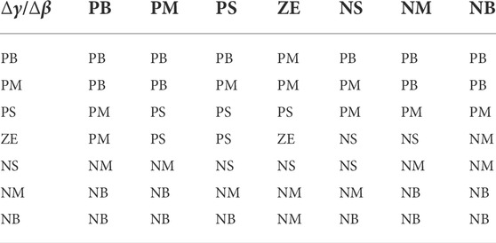
TABLE 1. Fuzzy controller rules table.
IF
3.3 Lower controller design
The lower controller chooses how much pressure is applied to each wheel’s brakes in order to deliver a net yaw torque that monitors the intended yaw torque value set by the higher controller.
The braking force on the left and right rear wheels is calculated using the relation in equation (Eq. 18), (Id et al., 2015), (Zhang et al., 2016)
Using the formula (Eq. 19), the pressure applied to the back wheels is determined where
4 Result
A tricycle vehicle with model characteristics that are presented in Table 2 is used in a co-simulation of MATLAB/Simulink and high-fidelity CarSim software simulations to assess the proposed controller’s efficiency to mitigate the Rollover Index. In this section, three scenarios are simulated. Longitudinal velocity is assumed to be 60 km/h, 55 km/h, and 50 km/h, and steering wheel angle is 130%, 150%, and 180% of Figure 5 double lane change maneuver respectively, which is unstable without a controller, and runs for 12 s to execute the closed-loop maneuver, for the lane change test, the weight coefficient ξ is set to 0.5, while the road friction coefficient µ is set to 0.9.
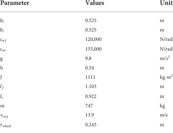
TABLE 2. Parameters that were utilized to validate the tricycle model (Yoon et al., 2007).
Under the controllers, the vehicle’s trajectory is capable of adhering to the predicted trajectory, the actual yaw rate able to track the desired value, and the actual sideslip angle can be controlled in a stable region. So that the vehicle rollover can be mitigated under the sliding mode controller as shown from Figure 9 and Figure 10 simulation result.
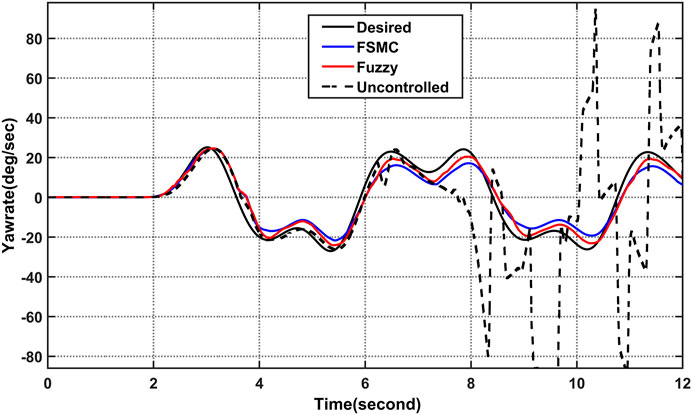
FIGURE 9. Simulation results comparison of yaw rate (
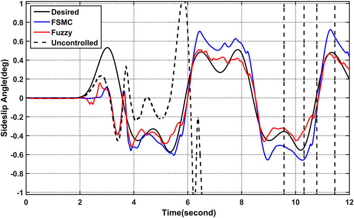
FIGURE 10. Simulation results comparison of sideslip angle (
Under the sliding mode controller’s and fuzzy controller’s Figure 11, it is important to mention, for the various pairings of unknown parameters in a closed loop scenario with carsim, the magnitude of the RI does not exceed the unit, as long as the closed loop, values of RI > 1 an accident that involved a rollover exists. To show the actual risk of rollover by a simple quantity, a dynamic rollover risk index is used. As seen in Figure 11, the RI is capable of both predicting and detecting a rollover state, and one of its capabilities is dependent on the longitudinal and lateral positions of the vehicle. Figure 12 illustrates the normalized vertical forces on the rear wheels as well as the RI for the worst case of parameter variation to be thorough. Note that when the vertical forces reach a zero value, the controller takes an action, so the rollover is mitigated. A greater perturbation or an exaggerated variation of a parameter can result in a rollover. That is, the presented strategy, like most active safety vehicular systems, is a driving assistance, and it is currently physically impossible to avoid the rollover in every scenario, implying that differential braking is insufficient to prevent the rollover As can be observed, the controlled vehicle’s response to yaw rate and sideslip angle can track their desired values of Eqs. 24, 25, longitudinal speed decreased as showed in Figure 13 and the absolute values of roll over index do not exceed the unit (Spanu et al., 2018).
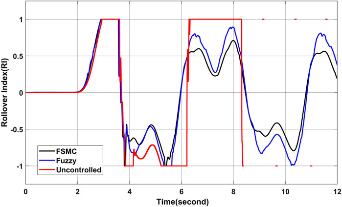
FIGURE 11. Simulation results comparison of rollover index (RI) value of maneuver of 180% amplitude increment at 50 km/h.
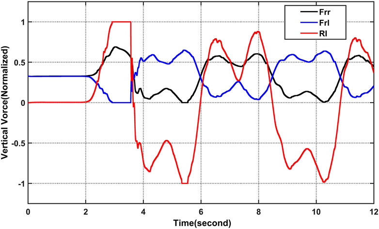
FIGURE 12. Comparison between the RI and the real vertical forces in the rear wheels (normalized), using a maneuver amplitude increment with fuzzy sliding mode controller.
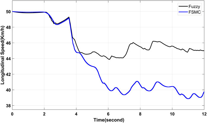
FIGURE 13. Longitudinal speed controller simulation result.
5 Discussion
Under open loop simulation by employing different maneuver and longitudinal speed as shown from the figure both the yaw rate and the sideslip angle deviate from their optimum values by significant amounts, one of rear wheel of the 3 W vehicle suffers the loss of ground contact, and the vehicle ends up with a rollover accident. As opposed to that, under the controllers, the vehicle’s trajectory is capable of adhering to the predicted trajectory, the actual yaw rate able to track the desired value, and the actual sideslip angle can be controlled in a stable region. so that the vehicle rollover can be mitigated under the sliding mode controller as well as fuzzy logic controller using rear differential brake system as shown from the simulation result.
6 Conclusion
This study presented the stability analysis of delta type three-wheel vehicles and proposed a sliding mode controller and fuzzy logic to handle the stability. First, a mathematical dynamic model of a delta-type tricycle vehicle was created, using Newton’s Law and fundamental physical principles, a dynamic rollover risk index is created. The mathematical model is then numerically validated, and the RI was carried out with excellent outcomes using high-fidelity carsim software. A rollover condition can be anticipated and detected by the RI. Later, the suggested car model was used to create a sliding mode and fuzzy controller, and their performance was evaluated with high-fidelity carsim software. Simulation outcomes demonstrated that the general SM and fuzzy controller could be applied successfully for 3-wheeled vehicles with rear differential breaking control actuation to increase the cars’ safety and stability. Within this thesis, a proposed sliding mode and fuzzy logic control to enhance driving stability and control produce brake torque to manage the sideslip angle and yaw rate. In this instance, the vehicle’s mobility is unsteady without the controller. However, the controller stabilizes the motion of the vehicle. and lower lateral motion is experienced. This paper recommends as a future work that design of an integrated controller that incorporates both rollover prevention and lateral stability controls.
Data availability statement
The datasets presented in this study can be found in online repositories. The names of the repository/repositories and accession number(s) can be found in the article/Supplementary Material.
Author contributions
DK designed a FSMC and/Fuzzy logic controller for mitigation/or prevention of rollover risk of front wheel drive tricycle vehicle, studied the performance of the designed controller on MATLAB/Simulink, and verified the dynamic model of tricycle vehicles using carsim software to show the effectiveness of rollover index (RI) to predict and detect the roll risks. SS validated the executed results of MATLAB/Simulink simulation using carsim software, supervised the whole research work, and reviewed the manuscript.
Funding
This research was conducted as a partial fulfillment of the Master of Science degree in Mechatronics Engineering by the fund provided from Addis Ababa Science and Technology University (AASTU), Ethiopia.
Conflict of interest
The authors declare that the research was conducted in the absence of any commercial or financial relationships that could be construed as a potential conflict of interest.
Publisher’s note
All claims expressed in this article are solely those of the authors and do not necessarily represent those of their affiliated organizations, or those of the publisher, the editors and the reviewers. Any product that may be evaluated in this article, or claim that may be made by its manufacturer, is not guaranteed or endorsed by the publisher.
Abbreviations
Fy, lateral tire force; Fx, longitudinal tire force; Fyfl, lateral force on the left front; t, tire; Fyfr, lateral force on the right front tire, Fyrl, lateral force on the left rear tire; Fyrr, lateral force on the right rear tire; Vx, vehicle's longitudinal speed at center of gravity; Vy, Vehicle's lateral speed at center of gravity; Vroll threshold, rollover threshold forward velocity, δ, steering wheel angle; m, vehicle's total mass; IZa, vehicle's yaw moment inertia; lw, track length (distance from right to left rear wheel); lf, distance from front wheel to center of mass; lr, distance from rear wheel to center of mass; L, total wheel base (lf + lr); b, vehicle track width; γ, vehicle's yaw rate (ψ)α, f, front tire slip angle; αr, rear tires slip angle; Cα, tire cornering stiffness; µ, coefficient of tire-road friction; Tbrl, left rear wheel's brake torque; Tbrr, right rear wheel's brake torque; Pbrl, left rear wheel's brake pressure; Pbrr, right rear wheel's brake pressure; γdes, yaw rate desired, β, vehicle's slip angle; βdes, slip angle desired; ay, lateral acceleration at center of gravity, aroll threshold, rollover threshold lateral acceleration at center of gravity; η, switch gain of sliding surface; rw, brake wheel radius; ξ, weight coefficient used in sliding surface; R, vehicle radius of curvature.
References
Anders, W. (2006). Yaw rate and lateral acceleration sensor plausibilisation in an active front steering vehicle. professional degree. Sweden: Linköping University.
Ataei, M. (2017). “Reconfigurable integrated control for urban vehicles with different types of control actuation,”. Doctoral Thesis (Canada: University of Waterloo).
Benariba, H., and Boumediene, A. (2018). “Lateral sliding mode control of an electric vehicle,” in Proceedings of the 6th International Conference on Control Engineering & Information Technology (CEIT), Istanbul, Turkey, October 2018. IEEE. doi:10.1109/CEIT.2018.8751932
Chen, C. (1999). [EE 501]Linear system theory and design. 3rd Edition. Oxford, United Kingdom: Oxford University Press.
Ebhota, W., Peter, O., Aduloju, S., and Austin, E. (2015). Determination of center of gravity and dynamic stability evaluation of a cargo-type tricycle. Am. J. Mech. Eng. 3 (1), 26–31. doi:10.12691/ajme-3-1-5
Ieee Centro Occidente Section and Institute of Electrical and Electronics Engineers (2018). “Centro Occidente section and Institute of electrical and Electronics Engineers,” in Proceedings of the IEEE International Autumn Meeting on Power, Electronics and Computing (ROPEC), Ixtapa, Guerrero, Mexico, November 2018. IEEE.
Licea, M. A. R., Rodríguez, E. A. V., Pinal, F. J. P., and Olivares, J. P. (2018). The rollover risk in delta tricycles: A new rollover index and its robust mitigation by rear differential braking. Math. Probl. Eng. 2018, 4972419. doi:10.1155/2018/4972419
Ling, F. F. (2006). Vehicle dynamics and control. Berlin, Germany: Springer. doi:10.1007/0-387-28823-6
Ojolo, S. J., Ajayi, O. O., and Asuelinmen, G. A. (2020). “Original research article rollover stability models for three-wheeled vehicle design,” 16, 92–99. [Online]. Available: www.azojete.com.ng
Pandey, A., Jha, S., and Chakravarty, D. (2017). “Modeling and control of an autonomous three wheeled mobile robot with front steer,” in Proceedings - 2017 1st IEEE International Conference on Robotic Computing, IRC 2017, Taichung, Taiwan, May 2017, 136–142. doi:10.1109/IRC.2017.67
Rodríguez-Licea, M.-A. (2021). “On the tripped rollovers and lateral skid in three-wheeled vehicles and their mitigation”. Vehicles 3, 357–376. doi:10.3390/vehicles3030022
Spanu, A., Stoenescu, F., Lorenzi, M., and Avram, M. (2018). Analysis of three wheeled electric vehicle with increased stability on the road. IOP Conf. Ser. Mat. Sci. Eng. 444 (4), 042010. doi:10.1088/1757-899X/444/4/042010
Yoon, J., Kim, D., and Yi, K. (2007). Design of a rollover index-based vehicle stability control scheme. Veh. Syst. Dyn. 45 (5), 459–475. doi:10.1080/00423110701245165
Zandieh, A. (2014). “Dynamics of a three-wheel vehicle with tadpole design,”. Master of Science (Ontario, Canada: University of Waterloo).
Zhang, S., Zhou, S., and Sun, J. (2009). “Vehicle dynamics control based on sliding mode control technology,” in Proceedings of the Chinese Control Decis. Conf. CCDC, Guilin, June 2009, 2435–2439. doi:10.1109/CCDC.2009.5192610
Zhang, S., Ding, S., and Jiang, H. (2016). “Direct yaw-moment control of in-wheel electric vehicle by sliding mode technique,” in Proceedings of the IEEE Int. Conf. Ind. Technol, Taipei, Taiwan, March 2016, 1844–1849. doi:10.1109/ICIT.2016.7475045
Ziane Achour University of Djelfa, and Fırat Üniversitesi Institute of electrical and Electronics Engineers (2019) “Algeria section, Institute of electrical and Electronics Engineers. Turkey section, and Institute of electrical and Electronics Engineers,” in Proceedings of the 4th International Conference on Power Electronics and their Applications (ICPEA 2019), Elazig, Turkey, September 2019.
Keywords: high-fidelity carsim, active fail-safe system, rear differential brake, bicycle vehicle model, roll-over, three wheeled vehicles
Citation: Ketemaw D and Seid S (2022) Design of a rollover index-based sliding mode controller for roll stability of three wheeled vehicles using rear differential braking. Front. Mech. Eng 8:1038289. doi: 10.3389/fmech.2022.1038289
Received: 06 September 2022; Accepted: 24 October 2022;
Published: 09 November 2022.
Edited by:
Jinlong Liu, Zhejiang University, ChinaReviewed by:
Meiyao Sun, Zhejiang University, ChinaHuachao Yang, Zhejiang University, China
Ziming Yan, Clemson University, United States
Copyright © 2022 Ketemaw and Seid. This is an open-access article distributed under the terms of the Creative Commons Attribution License (CC BY). The use, distribution or reproduction in other forums is permitted, provided the original author(s) and the copyright owner(s) are credited and that the original publication in this journal is cited, in accordance with accepted academic practice. No use, distribution or reproduction is permitted which does not comply with these terms.
*Correspondence: Solomon Seid, c29sb21vbnNlaWRAZ21haWwuY29t