 Yumin Zhang1
 Xigui Wang
- 1School of Engineering Technology, Northeast Forestry University, Harbin, China
- 2School of Mechatronics and Automation, Huaqiao University, Fujian Province, Xiamen, China
- 3School of Motorcar Engineering, Heilongjiang Institute of Technology, Harbin, China
The expected preloading effect of a hydraulic press frame parts (upper/lower semi-circular beams and columns) with pre-stressed by means of Winding Steel Wires which is directly related to the reliability and normal safe operation of the hydraulic press. The deformation of the Hydraulic Press Column (HPC) is an important indicator of the optimal preloading effect of the hydraulic press. A novelty of this project is to break through a bottleneck technology, the continuous cumulative deformation of a Hydraulic Press Column under seven time-varying steps is critical issues especially in theoretically calculated for a 20 MN double-frame hydraulic press with pre-stressed using WAW. A solid model with a pre-stressed frame is pre-designed by 3D software, and two simulation methods, equivalent pressure loading and equivalent temperature loading, are used to simulate and analyze the continuous cumulative deformation of the HPC under each step in Ansys Workbench software. By comparing the deformation and error analysis in the three cases above, the feasibility of the two simulation methods is verified, which leads to the advantages and disadvantages of each method in order to guide the subsequent design.
1 Introduction
With the rapid development of industrialization, large forging and pressing equipment has been widely used in the fields of aviation, aerospace, shipping, national defense and military fields, etc. It has become an important indicator of a country’s manufacturing level and industrial development capability (Zhu et al., 2002; Wei et al., 2016; Li et al., 2017; Yin et al., 2021; Wang and Chen, 2022). Compared with traditional large four-column presses, prestressed Winding Steel Wires (WSW) presses have the advantages of high fatigue strength, high load-bearing capacity, and no abrupt failure, therefore, prestressed WSW presses have been used in more and more industrial fields (Chukwulozie et al., 2016; Adesina et al., 2018; Reddy et al., 2019; Tazoe et al., 2019; Dong et al., 2020). At present, the design of prestressed WSW presses is still based on the traditional mechanical equations and theoretical model calculations to determine the structural size parameters and winding process of the presses, while there are certain structural differences between the actual produced presses and the theoretical model, which leads to the deviation of the calculated results from the actual values. With the continuous improvement of computer computing power, computer simulations based on FEA methods have been increasingly used in various fields of analysis and calculation (Zhu et al., 2012; Zhang et al., 2014; Amiolemhen and Ogie, 2019; Imran et al., 2019; Stishov, 2019). The use of FEA software for mechanical analysis and calculation of presses can simulate the actual model and actual working conditions more realistically, and the results are more accurate (Fulland et al., 2008; Duan and Wu, 2014; Lu and Zhu, 2018).
The prestressing WSW process is the key technology of the prestressing press. The standard for measuring whether the process meets the standards is the vertical deformation of the HPC after the WSW is pre-stressed. In this paper, the theoretical calculation, the simulation analysis of the equivalent pressure loading method and the simulation analysis of the cooling and pressurization method are used, and the three values are compared and analyzed to obtain the deformation of the HPC in the vertical direction, and the feasibility of the two simulation methods is verified.
2 Theoretical calculation of column deformation of pre-stressed WSW press
The deformation of the column of the 20 MN double-frame prestressing WSW press in the vertical direction is calculated according to the existing theoretical formula. The allowable value of the preloading factor η of the press is η = 1.2 ± .01, and the error between the theoretical and simulated values of the deformation of the HPC in the vertical direction is within 5%.
2.1 Structural dimensional parameters
It is known that the width of the upper and lower semicircular beams of the single frame of the 20 MN double frame prestressed WSW press is 1190 mm, the radius is 1225 mm, the width of the column is 1190 mm, the thickness is 350 mm, and the length is 3880 mm the number of WSW laid in each layer is 176, and the WSW are made of flat steel wires whose length is 5 mm and width is 1.5 mm the basic dimensional parameters of the frame model as shown in Figure 1.
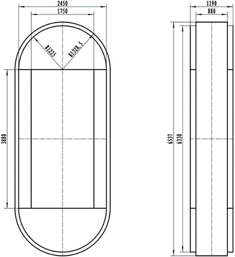
FIGURE 1. Press frame model structure size parameters.
The winding method of steel wire is divided into seven steps with variable tension, and the number of layers of each step is 5, 6, 8, 9, 12, 14 and 15, so the total number of layers of steel wire is 69, and the permitted tensile force of a steel wire is 1000 kg. The material parameters of the upper and lower semicircular beams, columns and wires are shown in Table 1.
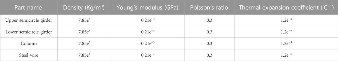
TABLE 1. Material parameters for each part of the frame.
2.2 Calculation of WSW tension and preload
From the basic parameters of the frame can be obtained by Eq. 1 the amount of stiffness ratio 68 of the WSW to the HPC is (Zhang et al., 2021).
where,
where,
Then the preloading force
where,
According to the basic parameters in the above Eqs 2-4, the wire tension of each step during winding, the preloading force applied to each step after winding, the deformation in the vertical direction of each step after winding is completed and the accumulated deformation of the HPC are shown in Table 2.
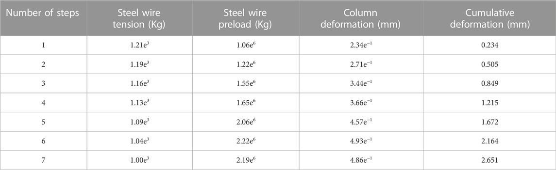
TABLE 2. Vertical deformation of HPC.
From the calculation in Table 2, the total preloading force value size after winding seven steps is 11,951.883 tons. Since the research object analyzed in this paper is 20 MN double frame prestressing winding press, the preloading factor
The preloading factor is within the permissible range and the parameter setting is reasonable.
3 Equivalent pressure loading on the HPC deformation calculation
After completing the pretensioning of the frame with wire winding, the upper and lower semicircular beams of the frame will be subjected to the uniform pressure of the WSW, which in turn will transfer the force to the HPC and cause it to deform. Therefore, the finite element analysis of the frame in the pretensioned condition will be performed by applying equivalent pressure to the upper and lower semicircular beams and using Ansys software to obtain the deformation values of its HPCs. Since the deformation of the HPC in the vertical direction is calculated in the theoretical calculation, the deformation results of the HPC in the vertical direction should be checked after the FEA calculation is completed, and then compared with the theoretical calculation results for analysis.
3.1 Equivalent pressure calculation
In this paper, the preloading force on the frame after winding each step is calculated, and the relationship between the preloading force generated after winding the ith step and the pressure
where,
The total pressure
where, n is the number of steps of winding.
The calculation from Eqs 6–7 shows that the magnitude of the pressure applied to the upper and lower semicircular beams after wrapping n steps is shown in Table 3.

TABLE 3. Value of pressure on the upper and lower semicircular beams.
3.2 Deformation calculation of HPC
The complete model of 20,000T double-frame prestressed WSW press is shown in Figure 2, but since the frame is analyzed and calculated by the theoretical model during the theoretical calculation, the simulation model should be ensured to be consistent with the theoretical model in order to ensure that the results of the theoretical and simulation calculations are comparable.
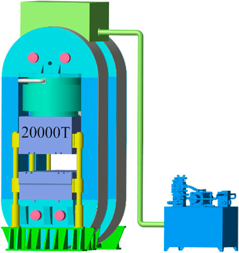
FIGURE 2. Model of pre-stressed WSW press.
The press model is simplified and modeled in the 3D software, and only the frame model is retained, 123 and the modeling is completed as shown in Figure 3.
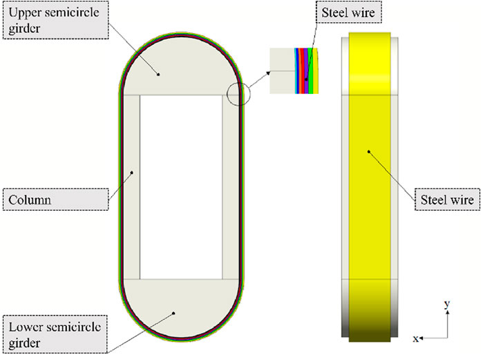
FIGURE 3. Framework simplified model.
In this topic, the deformation of the HPC is simulated and calculated by directly applying equivalent pressure to the contact surfaces of the upper and lower semicircular beams and the steel wire, so the steel wire structure is not considered when the finite element analysis is performed. The materials of each structure of the frame are set, and the contact relationship between the upper and lower semicircular beams and the HPC is set as friction contact, and its friction coefficient is 0.3.
In the theoretical calculation of the deformation of the HPC, the calculated deformation of the HPC in the vertical direction is obtained, while in the finite element analysis of the HPC, because the HPC not only produces deformation in the vertical direction, but also bending deformation occurs, which leads to the HPC in the vertical direction of any cross-section of its vertical deformation is different. Therefore, in order to make the comparative analysis between the theoretical calculated vertical deformation value and the simulation calculated value have reference significance, the intermediate section surface is created in the y-direction of the HPC by Construction Geometry in Ansys software, and then the resultant value of HPC deformation is taken as the resultant value of the y-direction deformation on this section.
Since the loading conditions of the frame are completely symmetric and unconstrained, it is necessary to turn on the weak spring to limit the degrees of freedom of the rigid body during the solution setting. In the solution setting, seven load steps are set, which correspond to the pressure values on the upper and lower semicircular beams after winding the steel wire in seven steps, and then the corresponding pressure values are entered on the contact surfaces of the upper and lower semicircular beams and the steel wire, respectively, and then the solution starts.
At the last time step, the total deformation of the frame as a whole is viewed as shown in Figure 4, and the vertical deformation of the HPC y-directional section is shown in Figure 5.
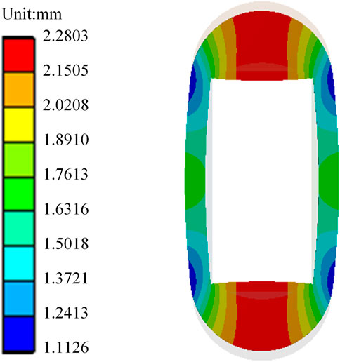
FIGURE 4. Overall frame deformation.

FIGURE 5. Vertical deformation of HPC y-direction section.
From the analysis of Figure 4, it can be obtained that the overall frame deformation shrinks inward, the result is symmetrical, and the deformation trend is consistent with the actual situation; from the analysis of Figure 5, it can be obtained that the deformation of the upper and lower ends of the HPC in the middle section in the y direction is basically the same, the deformation direction is opposite, the data is reasonable, and the maximum deformation is 1.2975 + 1.299 = 2.5965 mm the theoretical calculation value is 2.651 mm, then its error value is:
From the calculation of Eq. 8, the error between the theoretical and simulated values of the final HPC deformation in the vertical direction after winding seven steps is 2.112%, which is less than the error allowance of 5%, and the error is within the acceptable range.
Further, the deformation values of the HPC in the vertical middle section in the y-direction under seven loading steps were read and compared with the theoretical values to obtain the error of each step after loading with the theoretical values as shown in Table 4. In order to make the data analysis more intuitive, a line graph was drawn according to the data in Table 4 as shown in Figure 6.
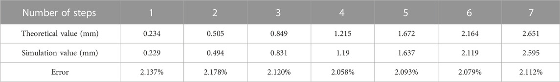
TABLE 4. Equivalent pressure loading error analysis.
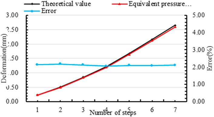
FIGURE 6. Equivalent pressure loading error analysis.
From the analysis of Table 4 and Figure 6, it can be obtained that the theoretical deformation of the HPC and the simulated deformation through pressure loading are basically the same after each step loading is completed, and the error values are around 2.0%, which is very small. Therefore, this simulation calculation method of simulating wire winding by pressure loading is feasible.
4 Equivalent temperature loading on the HPC deformation calculation
This subject simulates the pre-tensioning effect of the steel wire on the frame after winding by directly applying equivalent pressure on the contact surface of the upper and lower semicircular beams and the steel wire. Therefore, the steel wire structure must be considered when using the finite element method to simulate the working conditions of the press to calculate the performance of the press structure. The upper and lower semicircular beams of the frame are constrained by the pre-tensioned steel wire. Therefore, if the steel wire structure is ignored, the upper and lower semicircular beams lack constraints that limit their rigid body displacement and cannot be calculated. Therefore, when using the finite element method to simulate the working conditions of the press, the steel wire structure must be considered to calculate the performance of the press structure.
However, it is very difficult to directly simulate the actual wire winding process by FEA methods, so it is necessary to find an equivalent way to simulate wire winding. Based on the fact that most materials have the property of “thermal expansion and contraction”, the pre-tensioning effect of the wire on the frame can be simulated by applying an equivalent low-temperature load to the wire to make the wire shrink, while the rest of the frame structure remains at room temperature, a method called cooling and pressurization (Lei et al., 2018). Therefore, this subject will simulate the pre-tensioning effect of the wire rope on the frame by simulating this equivalent temperature loading method.
4.1 Equivalent temperature calculation
If we want to equivalently model the preload of the wire by equivalent temperature loading, we must know the equivalent temperature applied to the wire. The equation for the relationship between temperature and structural stress is known as (Okolie et al., 2020).
where,
Then the equivalent temperature value
where,
The tension applied to the wire rope for each step calculated in this subject is substituted into Equation (10) to obtain the equivalent temperature results applied to each step of the wire as shown in Table 5.

TABLE 5. Equivalent temperature of each step.
4.2 Deformation calculation of HPC
When the pre-tensioning effect of wire winding on the frame is simulated by equivalent temperature loading, it is a huge non-linear solution problem because the first layer of wire is linked with the frame by frictional contact, and the wire is also linked with the wire by frictional contact, and wires are laid in each layer, and a total of 79 layers are laid. Therefore, it is unrealistic to simulate the pre tensioning effect of wire winding exactly according to the actual situation, and some simplification and processing of the solution model are needed.
Firstly, the wire model is simplified, and since the equivalent temperature value loaded on the wire of each step is the same, the wire of each step is simplified to one layer of wire, and a total of seven layers of wire are modeled. Secondly, since the model is symmetric from front to back and left to right, one-quarter of the model is taken for the solution calculation and symmetric constraints are applied on the symmetry surface. Finally, the contact surface between the wire and the wire, the contact surface between the wire and the frame, and the contact surface between the upper and lower semicircular beams and the HPC are set as friction contact. Therefore, when setting the friction contact, we need to set the Interface Treatment to Adjust to Touch to make the friction take effect directly to offset the model gap generated by the contraction of the wire rope, and the friction coefficient is set to 0.3.
4.2.1 Solution setting
To simulate the preload effect of wire winding by means of equivalent temperature loading requires solving the temperature field results of the overall model before calculating the structural field results of the frame, so the problem is a thermodynamic coupled dual physical field coupled problem. Since the load loading of the frame is completely symmetric and unconstrained, it is necessary to turn on the weak spring to limit the degrees of freedom of the rigid body when solving the setup. It should be noted that since this paper simulates the wire preloading shrinkage by equivalent temperature loading, the temperature field obtained is also an equivalent temperature field, so when loading the equivalent temperature, the equivalent temperature should be applied to all nodes on the frame and the wire, not only on its surface, so that the heat conduction phenomenon occurs between the structure and the structure. Finally, the equivalent temperature corresponding to Table 4 is applied on the steel wire of each step, and the upper and lower semicircular beams of the frame and the steel wire are applied with a room temperature of 22 °C, and then the solution is performed.
4.2.2 View and analysis of results
After the solution is completed, the results of the overall temperature field distribution of the frame are shown in Figure 7, and the results of wire temperature field distribution are shown in Figure 8.
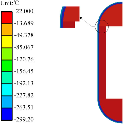
FIGURE 7. Overall temperature distribution of frame.
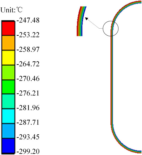
FIGURE 8. Steel wire temperature distribution chart.
Analysis by Figure 7 is intuitively seen, through the equivalent temperature loading, the wire rope produced a contraction effect, and then compress the frame to make it shrink inward, and the deformation results are symmetrical, which shows that this equivalent temperature loading simulation can simulate the contraction effect of the wire rope; analysis by Figure 8 is obtained, the HPC in the y direction of the middle section of the upper and lower ends of the deformation is basically the same, the deformation direction is opposite, the data is reasonable, and the maximum deformation is 1.276 + 1.278 = 2.554 (mm), and the theoretical calculation value is 2.651 (mm), then the error value is:
From the calculation of Eq. 11, the error between the theoretical and simulated values of the final HPC deformation in the vertical direction after winding seven steps is 3.659%, which is less than 5% of the allowable error value, and the error is within the acceptable range. Further calculate the deformation value of the HPC in the vertical middle section in the y-direction after each step winding is completed, and compare the analysis with the theoretical value to get the error between the theoretical value and the loaded value of each step as shown in Table 6. To make the data analysis more intuitive, a line graph is drawn according to the data in Table 6 as shown in Figure 9.
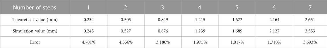
TABLE 6. Equivalent temperature loading error.
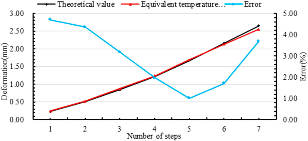
FIGURE 9. Equivalent temperature loading error analysis chart.
From the analysis of Table 6 and Figure 9, it can be concluded that the theoretical deformation of the HPC is basically the same as the simulated deformation of the cooling and pressurization loading. Although the error value of each step fluctuates, the allowable error value is less than 5%, so this simulation calculation method of equivalent temperature loading to simulate wire winding is feasible.
Further analysis shows that the error value tends to decrease first and then increase. In order to see the changes in the error value more clearly and intuitively, it is specially stipulated that when the simulated value is less than the theoretical value, the error value is negative and the error value is positive. This regulation leads to a comparative analysis of the errors of different loading methods calculated by two different simulation methods, pressure loading and equivalent temperature loading, as shown in Figure 10.
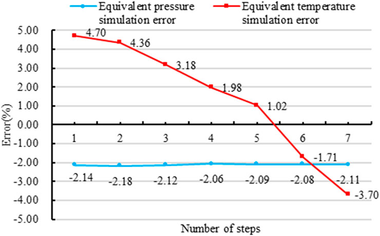
FIGURE 10. Comparison analysis of the error of the two loading methods.
From the analysis of Figures 4–6, the error value obtained by the equivalent pressure loading is small and consistent. This is because the pressure loading simulation process of different steps only changes the size of the pressure value and does not change other conditions, so the error value but the error value obtained by the equivalent temperature loading method shows a trend of first being positive and then gradually becoming negative. This is because as the number of winding steps increases, the number of wires increases, which in turn leads to an increase in the number of frictional contact pairs between the wires. Therefore, during the pre-tensioning process of the wire, it is also necessary to overcome the tangential friction between the wire and the wire. The more contact, the more work will be done to overcome the friction during the pre-tensioning, resulting in the wire tension is smaller than the theoretical value, so that the error value varies, but the error value is within 5% of the allowable error value, which does not affect the actual engineering application.
5 Experimental verifications of 20 MN pre-stressed WSW press
The feasibility of the two simulation methods has been proved in this paper. Therefore, the complete model of the frame is established by the 3D software, and the vertical deformation of the vertical center section of the HPC is calculated by the two simulation methods of equivalent pressure loading and equivalent temperature loading, and the resulting cumulative deformation values after winding each step are shown in Table 7.
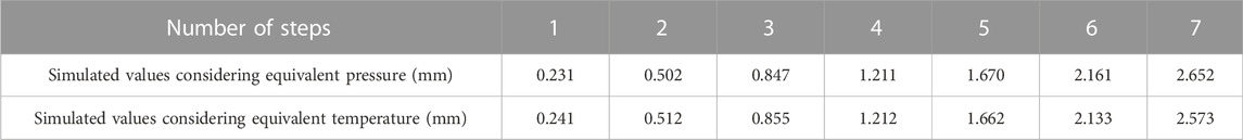
TABLE 7. HPC deformation calculated by simulation.
The winding process calculated is used to wind the frame. During the wire winding construction, the deformation of the HPC after winding each step was measured and recorded by a surveyor with a high-precision measuring tape as shown in Table 8.
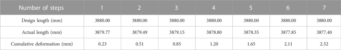
TABLE 8. Actual measured HPC deformation.
As can be seen from Table 7 and Table 8, the line diagram of the cumulative deformation of the HPC in the three cases is shown in Figure 11. The analysis of Figure 11 shows that the simulated value and the actual measured value under the two simulation methods fit well, but with the increase of winding layers, the actual measured value is relatively smaller than the simulated value and the theoretical value. This is because in the winding process between the wire rope and the wire rope also to overcome the work of friction, resulting in the relative reduction of the tension of the wire rope, which in turn leads to the deformation of the HPC is small, but such a small difference will not affect the actual engineering applications.
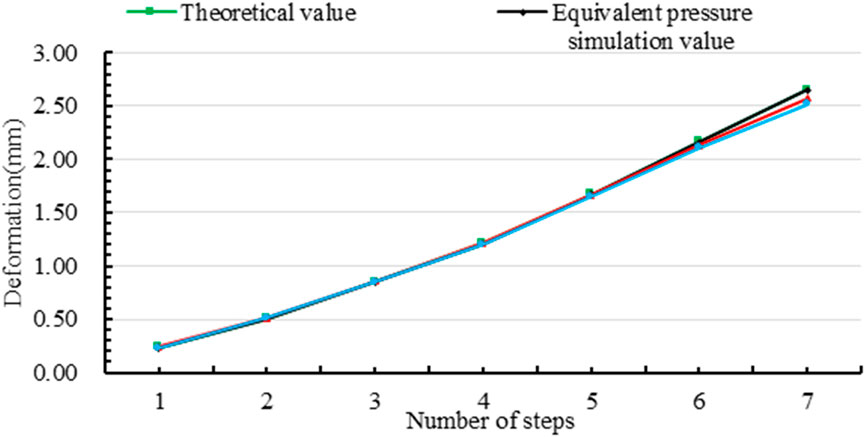
FIGURE 11. Comparison of cumulative deformation of HPCs.
According to the parameters designed in this paper, the site construction drawing of the frame for prestressing WSW is shown in Figure 12, and the final designed physical drawing of the 20 MN prestressing WSW press is shown in Figure 13. Over the years, users have used it well and the press and frame are in good condition.
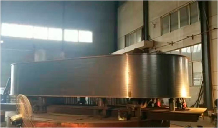
FIGURE 12. Frame winding site construction drawing.
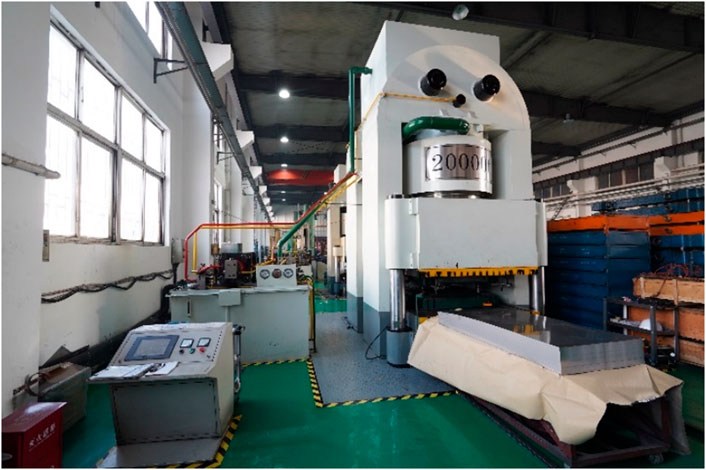
FIGURE 13. A 20 MN double frame press prototype.
6 Conclusion and discussion
This topic proposes a breakthrough in the pre-tightening stress analysis technology of Winding Steel Wires (WSW) double frames in the field of hydraulic presses. As discussed in the previous numerical calculations and simulation analysis, the following conclusions can be drawn:
1) Taking a 20 MN double-frame hydraulic press with prestressed WSW is used as the research object. Theoretical calculations show that the deformation of Hydraulic Press Column (HPC) in the vertical direction under the premise of meeting the preload coefficient requirements.
2) In Ansys Workbench software, two different loading methods (equivalent pressure loading and equivalent temperature loading) are used to simulate the pre-tightening effect of the prestressed WSW on the frame, and the vertical deformation value of the HPC in the vertical center section after each winding step is deduced, and compared with the theoretical value and analyzed the error to elaborate the following conclusions:
2.1) Using the equivalent pressure and temperature loading methods in Ansys, the error between the result and the theoretical value is within 5.0%, which meets the error requirements.
2.2) The equivalent pressure loading method only is applied to simulate the preload condition of the hydraulic press, and when simulating the working conditions of the double frames, considering the incomplete constraints, the upper and lower semicircular beams produce small rigid body displacements, which are difficult to solve and calculate accurately, the verification of the effective temperature is demonstrated through field experiments.
2.3) This study further demonstrates that the two simulation methods adopted in this paper are feasible in the actual hydraulic press engineering application, and have certain guiding significance for improving the prestressed WSW process.
Data availability statement
The original contributions presented in the study are included in the article/supplementary material, further inquiries can be directed to the corresponding authors.
Author contributions
Contributions of each co-author for the manuscript: XW is mainly responsible for writing manuscript, and presided over the organization of the overall work such as the structure of the paper and daily contact. He is responsible for the editing of diagrams and reference collection in the manuscript. YZ is responsible for the numerical simulation and algorithm analysis of the manuscript. YW is responsible for the language editing and writing logic of the manuscript.
Funding
The research subject was supported by the Doctoral Research Startup Foundation Project of Heilongjiang Institute of Technology (Grant No. 2020BJ06, YW, HLJIT), the Natural Science Foundation Project of Heilongjiang Province (Grant No. LH 2019E114, Baixue Fu, HLJIT), the Basic Scientific Research Business Expenses (Innovation Team Category) Project of Heilongjiang Institute of Engineering (Grant No. 2020CX02, Baixue Fu, HLJIT), the Special Project for Double First-Class-Cultivation of Innovative Talents (Grant No. 000/41113102, Jiafu Ruan, NEFU), the Special Scientific Research Funds for Forest Non-profit Industry (Grant No.201504508), the Youth Science Fund of Heilongjiang Institute of Technology (Grant No. 2015QJ02), and the Fundamental Research Funds for the Central Universities (Grant No. 2572016CB15).
Acknowledgments
The authors would like to thank the Northeast Forestry University (NEFU), Heilongjiang Institute of Technology (HLJIT), and the Harbin Institute of Technology (HIT) for their support.
Conflict of interest
The authors declare that the research was conducted in the absence of any commercial or financial relationships that could be construed as a potential conflict of interest.
Publisher’s note
All claims expressed in this article are solely those of the authors and do not necessarily represent those of their affiliated organizations, or those of the publisher, the editors and the reviewers. Any product that may be evaluated in this article, or claim that may be made by its manufacturer, is not guaranteed or endorsed by the publisher.
References
Adesina, F., Mohammed, T., and Ojo, O. (2018). Design and fabrication of a manually operated hydraulic press. Open Access Li brary J. 5, 1–10. doi:10.4236/oalib.1104522
Amiolemhen, P., and Ogie, N. A. (2019). Department of mechanical engineering, petroleum training Institute, effurun, delta state, Nigeria, design and manufacture of A 10-tonne hydrau lic press. J. Prod. Eng. 22 (1), 10–14. doi:10.24867/JPE-2019-01-010
Chukwulozie, O. P., Nnaemeka, O. E., and Andrew, A. O., (2016). Steel work design and analysis of a mobile floor crane. Curr. J. Appl. Sci. Technol. 13 (5), 1–9. doi:10.9734/BJAST/2016/23079
Dong, M. Y., Bao, M. L., and Hong, C. X. (2020). Analysis for the residual prestress of composite barrel f or railgun with tension winding. Def. Technol. 16 (4), 893–899. doi:10.1016/j.dt.2019.11.008
Duan, Z. D., and Wu, J. J. (2014). Topological optimization of frame of high-speed hydraulic press based on generalized finite element modules. Appl. Mech. Mater. 44-47, 1828–1832. doi:10.4028/www.scientific.net/AMM.44-47.1828
Fulland, M., Sander, M., Kullmer, G., and Richard, H. A. (2008). Analysis of fatigue crack propagation in the frame of a hydraulic press. Eng. Fract. Mech. 75 (3-4), 892–900. doi:10.1016/j.engfracmech.2007.01.006
Imran, M., Shi, D. Y., Tong, L. L., and Waqas, H. M. (2019). Design optimization of composite submerged cylindrical pressure hull using genetic algorithm and finite element analysis. Ocean. Eng. 19, 106443. doi:10.1016/j.oceaneng.2019.106443
Lei, Z., Xu, H., Zhang, B., Li, D. B., Wang, H. B., and Zi, B. (2018). Filament-wound composite sleeves of permanent magnet motor rotors with ultra-high fiber tension. Compos. Struct. 204, 525–535. doi:10.1016/j.compstruct.2018.07.119
Li, J. Q., Zheng, D. Y., Dong, C., Zhang, Z., Wang, F., Wang, Y. M., et al. (2022). Simulation an alysis of cylinder winding prestress based on Ansys. J. Phys. Conf. Ser. 2185 (1), 012006. doi:10.1088/1742-6596/2185/1/012006
Li, L., Huang, H., Zhao, F., Triebe, M. J., and Liu, Z. F. (2017). Analysis of a novel energy-efficient system with double-actuator for hydraulic press. Mechatronics 47, 77–87. doi:10.1016/j.mechatronics.2017.08.012
Lu, Y., and Zhu, J. (2018). Stress analysis of pre-stressed steel wire winding ultrahigh pressure vessels based on birth and death element method. Adv. Manuf. Automation 484, 655–662. doi:10.1007/978-981-13-2375-1_83
Okolie, P. C., Obika, E. N., Oluwadare, B. S., Ezenwa, O. N., and Udensi, C. S. (2020). Steel work design a nd analysis of a 40-ton constant temperature hydraulic press. Heliyon 6 (9), e04783. doi:10.1016/j.heliyon.2020.e04783
Reddy, A. R., Kumar, J., Yuvaraj, J. M., Vincent Joseph, P. V., and Shekar, K. (2019). Development of domes tic purpose hydraulic press oil expeller. Int. J. Eng. Res. Technol. 8 (6), 125–128. doi:10.17577/IJERTV8IS060046
Stishov, S. M. (2019). A small laboratory hydraulic press with a force of 20 tons. Instrum. Ex perimental Tech. 62, 708–709. doi:10.1134/S0020441219040213
Su, W., Zhang, X., Wei, K., Su, Z., and Wang, D. (2019). Pre-stress dynamic performance during filament winding with tension. Acta Mater. Compos. Sin. 36 (5), 1143–1150. doi:10.13801/j.cnki.fhclxb.20180821.003
Tazoe, K., Tanaka, H., Oka, M., and Yagawa, G. (2019). Analyses of fatigue crack propagation with smooth ed particle hydrodynamics method. Eng. Fract. Mech. 228, 106819. doi:10.1016/j.engfracmech.2019.106819
Wang, J., and Chen, C. (2022). A nonlinear vibration compensation method for engineering forging Hydra ulic press using tabu search algorithm. Mob. Inf. Syst. 2022, 1–10. doi:10.1155/2022/3731211
Wei, J. H., Zhang, Q., Li, M., and Shi, W. Z. (2016). High-performance motion control of the hydraulic press based on an extended fuzzy disturbance observer. J. Syst. Control Eng. 230 (9), 1044–1061. doi:10.1177/09596518166625
Wu, J. F., Lan, J. B., Hu, K., and Li, Q. L. (2014). The fatigue life analysis of prestressed wire-wound super-high pressure vessel based on ANSYS. Appl. Mech. Mater. 552, 8–14. doi:10.4028/www.scientific.net/AMM.552.8
Yin, D. M., Li, B. M., and Xiao, H. C. (2019). Simulation of the winding angles’ influence on the dynamic strength and stiffness of filament wound composite barrel for railgun. IEEE Trans. Plasma Sci. 47 (5), 2233–2241. doi:10.1109/TPS.2018.2890453
Yin, S., Yang, H., Xu, K., Zhu, C., and Wang, Y. (2021). Location of abnormal energy consumption and opti mization of energy efficiency of hydraulic press considering uncertainty. J. Clean. Prod. ion 294, 126213. doi:10.1016/j.jclepro.2021.126213
Zhang, W. J., Yuan, X. F., Chen, C., and Yang, L. (2021). Finite element analysis of steel wire ropes consid ering creep and analysis of influencing factors of creep. Eng. Struct. 229, 111665. doi:10.1016/j.engstruct.2020.111665
Zhang, W., Wang, X., Wang, Z., and Yuan, S. (2014). Structural optimization of cylinder-crown integrated hydraulic press with hemispherical hydraulic cylinder. Procedia Eng. 81, 1663–1668. doi:10.1016/j.proeng.2014.10.209
Zhu, P., Zhang, L., Zhou, R., Chen, L., Yu, B., and Xie, Q. (2012). A novel sensitivity analysis method in str uctural performance of hydraulic press. Math. Problems Eng. 2012. doi:10.1155/2012/647127
Zhu, Y., He, Y., and Ren, J. (2002). “Structure analysis and optimization design of the base of four-pillar hydraulic testing machine,” in Journal of Physics: Conference Series, 7th International Conference on Machinery, 24-25 July 2021 (Hangzhou, China: Material Science and Engineering Application), 012036.
Keywords: hydraulic press, pre-stressed, wire-winding hydraulic press, double frame column deformation, numerical calculation, simulation analysis
Citation: Zhang Y, Wang X and Wang Y (2023) Numerical calculation of a 20MN heavy duty hydraulic press for analyzing the double frame pre-stressed steel wire winding. Front. Mech. Eng 8:1086124. doi: 10.3389/fmech.2022.1086124
Received: 01 November 2022; Accepted: 12 December 2022;
Published: 04 January 2023.
Edited by:
Chitarajan Pany, Vikram Sarabhai Space Centre, IndiaReviewed by:
Gireesha Chalageri, KLE Technological University, IndiaAbbas Heydari, Technical and Vocational University, Iran
Copyright © 2023 Zhang, Wang and Wang. This is an open-access article distributed under the terms of the Creative Commons Attribution License (CC BY). The use, distribution or reproduction in other forums is permitted, provided the original author(s) and the copyright owner(s) are credited and that the original publication in this journal is cited, in accordance with accepted academic practice. No use, distribution or reproduction is permitted which does not comply with these terms.
*Correspondence: Xigui Wang, d3hnMTk3MkBuZWZ1LmVkdS5jbg==; Yongmei Wang, d3lyMjAwOTEyMDdAMTI2LmNvbQ==