 Emanuel Willert
- Institute of Applied Mechanics, Technische Universität Berlin, Berlin, Germany
The subsurface elastic stress fields in plane and axisymmetric contacts with friction under oscillating tangential loading are calculated via a very robust, high-precision method, which operates with appropriate superpositions of analytic solutions for the respective Hertzian contact problems. Based on the stress fields, two critical plane fatigue crack initiation criteria—the Smith-Watson-Topper (SWT) parameter and the Findley parameter—are evaluated for three types of contact profile geometries: (unworn) parabolic contact, the partial slip limiting wear profile of an initially parabolic contact, and truncated parabolic contact. Appropriate scaling laws are introduced to formulate a general solution in terms of non-dimensional variables. The crack initiation criteria are determined in the full subsurface loading plane. It is found that the truncated profile—which may originate from sliding wear—has practically the same local distribution of crack initiation criteria as the unworn profile, despite the (weak) stress singularity at the edge of the flat face. The partial slip limiting wear profile, on the other hand, exhibits a strong edge stress singularity at the boundary of the permanent stick zone, the crack initiation criteria are drastically increased (and theoretically infinite). Also, while for the unworn and truncated profiles high values of the crack initiation criteria are extremely localized around “hotspots” at the surface, for the partial slip limiting wear profile they reach much deeper into the subsurface material. This offers a new explanation for the dominance of fatigue failure in the partial slip regime of fretting. The differences between plane and axisymmetric cases are generally small. The SWT parameter is generally more localized than the Findley parameter.
1 Introduction
Fretting is a long-known source of damage and failure in various technical or biotechnological tribosystems that are subject to small-amplitude oscillations, e.g., in prostheses (Collier et al., 1992), electrical connectors (Antler, 1985) or dovetail joints (Ciavarella and Demelio, 2001). Depending on the oscillation amplitude (compared to the characteristic contact length), and the resulting frictional contact configuration, different fretting regimes can be distinguished (Vingsbo and Söderberg, 1988)—the partial slip regime, the gross sliding regime and a mixed regime between the former two. Fretting causes different types of mechanical damage, mainly various forms of wear, as well as fatigue cracking. While in the partial slip regime specimen lifetime is diminished mainly by fatigue, in the sliding regime the main damage phenomenon seems to be wear (Vingsbo and Söderberg, 1988). Because of this, supposedly clear, distinction and due to the computational difficulties in creating a comprehensive model framework that incorporates both phenomena, fretting wear and fretting fatigue had for a long time been understood as competing, but more or less separate processes (Berthier et al., 1989), until Madge et al. (Madge et al., 2007) pointed out the critical role of fretting wear for the analysis of the respective fatigue problem. That sparked a series of publications by different research groups in recent years on the influence of wear on fretting fatigue, especially in the partial slip regime, using a combination of two-dimensional finite element (FE) calculations with a local energy-based or Archard wear law, and critical plane fatigue crack initiation criteria (Madge et al., 2008; Zhang et al., 2011). The corresponding models have been used to simulate, e.g., fretting of hip implants (Zhang et al., 2013) or thin steel wires (Cruzado et al., 2013). Implemented improvements of that approach include the consideration of plasticity (Shen et al., 2015), the use of critical distance theory (Cardoso et al., 2019; Llavori et al., 2019) to account for the fact, that due to the high contact stress gradients a strictly local formulation of crack initiation criteria might be overly conservative (Gandiolle and Fouvry, 2016), and the influence analysis of wear debris (Wang et al., 2022).
The main predictive “bottleneck” of the models cited above is the wear law, as the appropriateness of a local Archard or energy-based wear law in partial slip fretting conditions is debatable, especially if the wear is predominantly adhesive (Fouvry et al., 2007). That is why in the present manuscript a simplified problem is analyzed in detail, that can still shed new light on the influence of fretting wear on fretting fatigue, namely the question, how the elastic “fields” of fatigue crack initiation criteria (to be more precise, critical plane parameters) differ between an initial unworn profile geometry and some representative, long-term worn profiles, without specifying the concrete wear dynamics.
In the following manuscript, the Sections 2–4 are devoted to problem formulation and modelling. In the Sections 5–7 the obtained results regarding two critical plane criteria, namely the Smith-Watson-Topper and Findley parameters, for different plane and axisymmetric profile geometries are shown. A discussion and conclusive remarks finish the manuscript.
2 Problem Statement
2.1 General Assumptions
Let us consider single contacts of linearly elastic, homogeneous, isotropic bodies with the shear moduli G1 and G2 and Poisson’s ratios ν1 and ν2 under normal and tangential loading. For the normal and tangential contact problems to be elastically decoupled, the materials shall be elastically similar,
The contacting bodies are assumed to obey the restrictions of the half-space approximation. Effects of surface roughness or adhesion are neglected and friction is considered within the framework of a local Amontons-Coulomb law with a constant coefficient of friction µ. Within these assumptions, the contact is equivalent to the one between an elastic half-space with the effective modulus
and a rigid indenter. The indenter shall be under a constant normal load and an oscillating tangential load. If we introduce a cartesian coordinate system with z being the normal axis pointing into the elastic half-space, x being the direction of tangential loading, and y being the remaining lateral direction, we can define the indenter profile f as the gap between the two contacting bodies in the moment of first contact,
We will consider plane profiles f2D = f2D(x) under plane strain conditions, and axisymmetric profiles faxi = faxi(r), with r being the polar radius in the {x, y} contact plane. For plane contacts, the load is to be understood as per unit length in the lateral direction. A scheme of the analyzed problem and further notations for the contact solutions are given in Figure 1. Note that—as the present manuscript is not concerned with the possible crack propagation or arrest—no global prestresses in the elastic half-space are considered, although large-enough prestresses (which are comparable to the “pure” contact stresses) can alter the contact solution and thus the subsurface stress fields in a nontrivial manner. However, in elastic half-space contact mechanics, these prestresses can be incorporated analytically, at least in the case of plane contacts (Hills and Nowell, 1994).
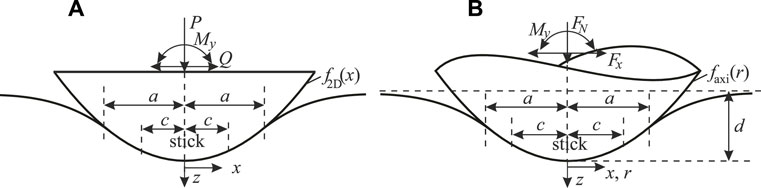
FIGURE 1. Oscillating tangential contact between a rigid indenter and an elastic half-space. (A) plane contact (B) axisymmetric contact.
2.2 Analyzed Profile Geometries
2.2.1 The “Benchmark”: Parabolic Contact
First, the unworn parabolic (Hertzian) profile with the radius of curvature R will be analyzed. Note that another very common unworn profile in fretting contacts is the rounded flat punch; nonetheless, for plane geometries, the differences regarding fretting wear and fatigue between the parabolic and rounded flat punch cases have already been studied in detail (Zhang et al., 2011).
2.2.2 Partial Slip Limiting Wear Profiles of Initially Parabolic Contact
In partial slip elastic fretting contacts, which are subject to some form of local wear—with the local intensity of wear being a function of the local contact pressure and the local slip velocity—there generally exists a limiting no-wear state, if at the beginning of the wear process a region of the contact area is permanently stuck during the fretting oscillation. As wear will only occur in the slip region, during the wear process normal load is transferred to the permanent stick region, which therefore remains stuck and hence unworn, until the slip region is free of contact pressure (i.e., in incipient contact), and therefore does not wear any further. From these considerations it is clear that the worn profile in the limiting no-wear state is given by the elastic normal displacements due to the indentation in the permanent stick area. As the latter are known from the respective normal contact solution, this allows to determine the limiting no-wear profile.
For a plane, initially parabolic contact, the limiting profile was determined by Hills et al. (Hills et al., 2009). It is
where cmin is the half-width of the permanent stick region and a0 is the initial contact half-width. The final contact half-width a∞ follows from the condition that the profile coincides with the unworn parabolic profile.
For an axisymmetric, initially parabolic contact, the limiting profile was published by Popov (Popov, 2014),
Here, the final indentation depth d∞ under force-controlled conditions is easily determined from the corresponding normal contact solution.
2.2.3 Truncated Parabolic Contact
In sliding conditions one can imagine the result of wear being that the complete tip of the parabolic indenter is worn off at a specific height (although that is strictly correct within the framework used only for displacement-controlled conditions). Thus, let us introduce the truncated plane parabolic profile,
and the axisymmetric analogue,
Here, b denotes the half-width or radius of the flat face of the worn-off indenter tip and H() is the Heaviside step function.
3 Superposition Procedure for the Surface and Subsurface Stress States
The determination of critical plane fatigue crack initiation criteria is based on the knowledge about the full surface and subsurface states of stress and deformation. A very fast and robust procedure for the determination of subsurface stresses in elastic contacts, which is based on the appropriate superposition of respective solutions for the parabolic (i.e., Hertzian) contact, has been proposed very recently by the author (Willert, 2021a), and will in the following be laid out briefly.
3.1 Normal Contact
If the contacting bodies are elastically similar, the stress contributions resulting from the normal and tangential loadings can be separated. First, we consider the stress state due to the normal load.
3.1.1 Plane Contacts
In plane normal contacts, the only well-defined macroscopic contact quantities are the normal line load P and the contact half-width a, because the displacements can only be defined relative to an arbitrary reference. In the case of single symmetric contacts of convex profiles, the function P(a) is bound to the symmetric plane profile via the Abel-like integral transform (Barber, 2018)
which can be written as an explicit convolution introducing the substitutions
which via integrating by parts leads to
This convolution can be evaluated in a very efficient manner with the 1D Fast Fourier Transform (FFT), as has been demonstrated recently for a similar transform arising in the case of axisymmetric contacts (see below) (Willert, 2021b). Once the relation between P and a is known for a given profile, the subsurface stress state due to the normal loading can be determined from an appropriate superposition of stress states for the plane Hertzian contact (Willert, 2022),
where the stress field for the plane Hertzian contact, denoted by the upper index “H,N”, can be referenced in Muskhelishvili’s (Muskhelishvili, 1958) full solution of the plane parabolic normal contact problem.
3.1.2 Axisymmetric Contacts
In the axisymmetric case, the indentation depth d is well-defined and bound to the contact radius via the Abel-like integral transform of the axisymmetric profile (Popov et al., 2019)
which, similarly to the transform (8), can be written as an explicit convolution and therefore very efficiently evaluated with the 1D-FFT, using the substitutions
and the full subsurface stress state due to the normal loading can be determined from an appropriate superposition of stress states for the axisymmetric Hertzian contact (Willert, 2021a),
where the stress field for the axisymmetric Hertzian contact, denoted by the upper index “H,N”, has been given in explicit form by Huber (Huber, 1904) and Hamilton (Hamilton, 1983).
3.2 Cattaneo’s Problem
Let us now focus on the tangential loading contributions to the subsurface stress state. In general, the contact configuration, and therefore obviously also the subsurface stresses, in tangential contact problems depend on the loading history. In this subsection the superposition procedure of the subsurface stresses is shown for Cattaneo’s (Cattaneo, 1938) problem, i.e., the simplest loading history of a constant normal load and a subsequently applied increasing tangential load. Fretting configurations in the form of an oscillating tangential load are considered in the next subsection. As Cattaneo’s problem, within the framework of the assumptions stated before, can be reduced to the pure normal contact problem via the principle of Jäger (Jäger, 1998) and Ciavarella (Ciavarella, 1998a; Ciavarella, 1998b), the stress superposition works similarly as in Equations 11, 14.
3.2.1 Plane Contacts
In single symmetric plane contacts, the principle of Jäger and Ciavarella states, that the tangential line load Q and the frictional shear tractions in the contact, q(x), are given by
with the pressure distribution p(x). Here, c < a denotes the half-width of the inner stick region. If c is used as a parameter for the normal contact solution, it refers to a (fictious) normal contact configuration with the contact half-width c. As is Equation 11, because of the reduction of the tangential contact problem with friction to the normal contact problem, the subsurface stress state due to the tangential loading can be obtained by an appropriate superposition of stresses arising from the tangential loading under a sliding plane Hertzian contact (Willert, 2022),
where the stress field arising from the shear tractions in the sliding plane Hertzian contact, denoted by the upper index “H,C”, can be easily determined from Muskhelishvili’s full solution of the plane parabolic normal contact problem (Willert, 2022).
3.2.2 Axisymmetric Contacts
For axisymmetric contacts the principle of Jäger and Ciavarella is exactly correct only for materials without transverse strain, i.e., with ν = 0. However, the error made by applying the principle for general materials has been shown to be usually small (Munisamy et al., 1994). The relations for the total tangential force and the shear tractions in the contact are completely analogous to the plane case,
Again, c (physically being the radius of the inner stick area) as a parameter of a normal contact solution corresponds to a (fictious) normal contact problem with the contact radius c. In complete analogy to Equation 16, the subsurface stress state due to the tangential loading can be obtained by an appropriate superposition of stresses arising from the tangential loading under a sliding axisymmetric Hertzian contact (Willert, 2021a),
where the stress field arising from the shear tractions in the sliding axisymmetric Hertzian contact, denoted by the upper index “H,C”, has been given in explicit form by Hamilton (Hamilton, 1983).
3.3 Oscillating Tangential Loading
As stated, the superposition rules in Equations 16, 18 are valid only for the simplest loading history of a constant normal load and a subsequently applied increasing tangential load. For the slightly more complicated case of a constant normal load with an oscillating tangential load we will apply yet another superposition idea, which was first used by Jäger (Jäger, 1993) for the tangential contact of spheres under arbitrary oblique loading.
Just before reversing the direction of tangential loading, the half-width (or radius) of the inner stick zone reaches its minimum value, cmin. When reversing the loading direction, there is a spontaneous moment of complete stick (because, according to the friction law, all slipping points are in the “limiting state of stick”, |q| = µp), after which a new slip area propagates from the contact edge, with the slip direction reversed. Due to the specific form of the Equations 15, 17, the shear tractions after reversing the loading direction are for the plane contact
and similarly, for the axisymmetric case. As all underlying equations are linear, the same superposition will be correct for the subsurface stress state arising from the tangential loading. Hence, for the full stress state resulting from the tangential loading, we have
where the different signs correspond to the first and second half-cycles of the loading oscillation, respectively. The current half-width (or radius) of the stick zone, c, can be easily determined from the current value of the tangential load; integrating Equation 19 over the contact area gives
and similarly, for the axisymmetric case. Finally, the complete stress state is given by the sum of
4 Determination of Multiaxial Critical Plane Fatigue Crack Initiation Criteria
Critical plane fatigue crack initiation criteria consider the stresses and deformations in specific planes at specific points, which are identified as critical, depending on the dominant cracking failure mode of the material. In the previous section, a fast, precise and robust procedure has been presented to determine the elastic stress tensor in and under the surface. From Hooke’s law, the corresponding strain tensor εij can be immediately deduced. To reduce the number of free parameters and to allow for a concise representation of the problem solution, we will make the reasonable assumption that the critical point and the normal vector of the critical plane are in the {x, z} loading plane (for plane problems that is true by symmetry). Hence, to determine the scalar values of normal and tangential stresses and strains in specific planes, we introduce the normal and tangential vectors of the plane as
The normal stresses and strains, and the tangential stress in the corresponding plane are
4.1 Smith-Watson-Topper Parameter
The SWT parameter (Smith et al., 1970) is a crack initiation criterion that is based on the normal strain energy. It is defined as
Here, the upper index “max” of the stress and the amplitude of the deformation are to be understood as over one cycle of the fretting oscillation. The lower index “max” indicates maximizing with respect to the orientation of the plane, for which the expression in brackets is evaluated (Socie, 1987). The SWT parameter can be connected to the specimen lifetime (measured in oscillation cycles to initiate a crack of given length) (Szolwinski and Farris, 1996). If for that procedure a strictly local value of the SWT is used, the lifetime estimates are usually conservative, because the contact stresses vanish rapidly in the material within a characteristic length, which is of the same order as the characteristic contact size. That is why, for lifetime estimates often parameter values are used, which are “averaged” in some sense over a given volume (Araújo et al., 2004), or which are evaluated in some critical distance from the hotspot (Gandiolle and Fouvry, 2016). However, as the present manuscript is not concerned with lifetime estimates, but only with the influence of the profile geometry on the behavior of the crack initiation criteria, nonetheless only strictly local parameters will be considered. The characteristic gradients of the parameters, which might be of interest for the choice of the “averaging volume”, can be calculated easily from the strictly local results.
4.2 Findley Parameter
The Findley parameter (Findley, 1959) is based on the shear stress amplitude on the critical plane, but also considers the maximum normal stress acting on that plane. It is defined as
As before, the upper index “max” of the normal stress and the amplitude of the shear stress are to be understood as over one cycle of the fretting oscillation. The lower index “max” indicates maximizing with respect to the orientation of the plane, for which the expression in brackets is evaluated. The parameter k, characterizing the influence of the maximum normal stress, depends on the material. For ductile materials one should expect k to be small. Although originally not intended as such, the Findley parameter, too, can be used to calculate lifetime until crack initiation (Bhatti and Abdel Wahab, 2018).
5 Critical Plane Fatigue Crack Initiation Criteria for Parabolic Contact
In this section, the results obtained with the model described above will be shown for the parabolic contact profile. First, to allow for a general solution representation, the relevant scaling laws are given, after which the correctly scaled results for plane and axisymmetric contacts are shown.
5.1 Scaling Laws
Both the SWT and Findley parameters have physical dimensions. Hence, the number of free influencing variables can be reduced by introducing non-dimensional quantities and formulating appropriate scaling laws. The characteristic scale of deformation in the Hertzian contact is aH/R. The SWT parameter is a strain energy, the Findley parameter a characteristic stress. We therefore can introduce the scales
Note that ε0 is a non-dimensional measure of the constant normal load. Hence, the correct non-dimensional versions of the fatigue crack initiation criteria are
where the loading ratio T has been introduced, which is Qmax/(µP) for plane contacts and Fx,max/(µFN) for axisymmetric contacts. The dependence on Poisson’s ratio is relatively weak, and the dependencies on the friction coefficient and loading ratio are quite simple: increasing µ or T will increase the crack initiation parameters. For all simulations k = 0.2, ν = 0.3, and µ = 0.7 were chosen. In plane contacts, a loading ratio of T = 0.5 was chosen, while for axisymmetric contacts T = 0.65—both correspond to a relative extent of the minimum stick zone in parabolic contact of cmin/a ≈ 0.7. Note that this loading ratio was also used for the truncated profiles to retain comparability of the results. The plane orientation angle θ was always resolved in quarters of a degree.
5.2 Results for Plane Contact
In Figure 2 the contour line diagrams of the scaled SWT and Findley parameters are shown in the subsurface loading plane for the case of plane parabolic contact. Both fatigue parameters have extremely localized maxima at the contact edge and are vanishing inside the material with a characteristic length that is well below the characteristic contact size. The SWT parameter is even more localized than the Findley parameter, and it is negative in and below the permanent stick area. The hotspot for the SWT parameter is at x = aH and z = 0, i.e., the contact edge, with a maximum scaled SWT parameter of 0.24 at a critical angle θ = 90.5π/180, i.e., the critical plane is oriented basically perpendicular to the contact plane. The hotspot for the Findley parameter is at x = 0.995aH and z = 0, with a maximum scaled Findley parameter of 0.30 at a critical angle θ = 54.25π/180. These results are in reasonable agreement with experimental data from the literature (Bhatti and Abdel Wahab, 2018).
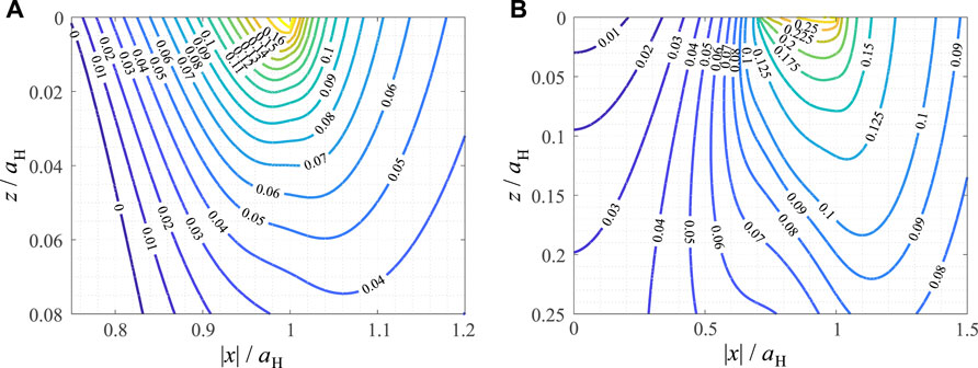
FIGURE 2. Contour line diagrams of critical plane fatigue crack initiation criteria, normalized for their characteristic scales, in the loading plane for a partial slip plane parabolic contact under oscillating tangential load. (A) Smith-Watson-Topper parameter (B) Findley parameter.
5.3 Results for Axisymmetric Contact
In Figure 3 the contour line diagrams of the scaled SWT and Findley parameters are shown in the subsurface loading plane for the case of axisymmetric parabolic contact. The results are very similar to the plane case. Both parameters have extremely localized maxima at the contact edge and are vanishing inside the material with a characteristic length that is well below the characteristic contact size. The SWT parameter is even more localized than the Findley parameter, and it is negative in and below the permanent stick area. The hotspot for the SWT parameter is, again, at x = aH and z = 0, with a maximum scaled SWT parameter of 0.42 at a critical angle θ = 90.5π/180. The hotspot for the Findley parameter is at x = 0.96aH and z = 0, with a maximum scaled Findley parameter of 0.38 at a critical angle θ = 61π/180.
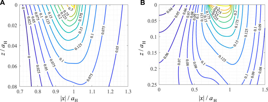
FIGURE 3. Contour line diagrams of critical plane fatigue crack initiation criteria, normalized for their characteristic scales, in the loading plane for a partial slip axisymmetric parabolic contact under oscillating tangential load. (A) Smith-Watson-Topper parameter (B) Findley parameter.
6 Critical Plane Fatigue Crack Initiation Criteria for Partial Slip Limiting Wear Profiles
6.1 Scaling Laws
Due to the strong edge stress singularity that emerges at the boundary of the permanent stick region, for the partial slip limiting wear profile the critical plane crack initiation criteria are, theoretically, divergent in the whole vicinity of the contact, with the respective maximum values depending on the resolution of the simulation. However, if the resolution is fine enough, the scaled variables
are unique, i.e., independent of the model discretization. The maximum values of the parameters scale very roughly with the maximum contact pressure pmax at the edge of the permanent stick area, obtained in the simulation, SWTmax ∼ (pmax)2/E* and FPmax ∼ pmax. In reality, the stress singularity is bound by plasticity or material strength. If we assume that yield is highly localized around the singular point and not affecting the elastic stress fields in most of the subsurface regions, the scaled elastic solution can still be used to estimate the range behavior of the fatigue parameters. Note however, that plasticity might allow for the wear to penetrate the permanent stick region (Hu et al., 2016).
6.2 Results for Plane Contact
In Figure 4 the contour line diagrams of the scaled SWT and Findley parameters are shown in the subsurface loading plane for the case of plane contact. Their maxima are significantly less localized than in the unworn case, the “fields” of the fatigue parameters range significantly deeper into the material. Also, the Findley parameter takes its maximum value in almost the whole contact area, while in the unworn case, the critical point is clearly only the contact edge. The hotspot for the SWT parameter is at x = 1.165aH = a∞ and z = 0, i.e., at the edge of the limiting contact area, with a critical angle θ = 92.5π/180. Stating a “hotspot” for the Findley parameter does not make too much sense, as the parameter assumes its maximum value almost everywhere in the slip area.
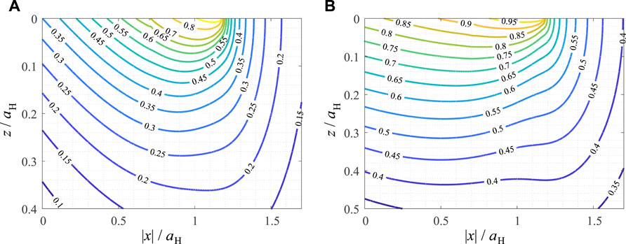
FIGURE 4. Contour line diagrams of critical plane fatigue crack initiation criteria, normalized for their maximum values, in the loading plane for the plane partial slip limiting wear profile under oscillating tangential load. (A) Smith-Watson-Topper parameter (B) Findley parameter.
6.3 Results for Axisymmetric Contact
In Figure 5 the contour line diagrams of the scaled SWT and Findley parameters are shown in the subsurface loading plane for the case of axisymmetric contact. The results are, once again, qualitatively very similar to the plane case. The hotspot for the SWT parameter is at x = 1.22aH = a∞ and z = 0, i.e., at the edge of the limiting contact area, with a critical angle θ = 93π/180. Stating a “hotspot” for the Findley parameter, again, does not make too much sense, as the parameter assumes its maximum value almost everywhere in the contact area.
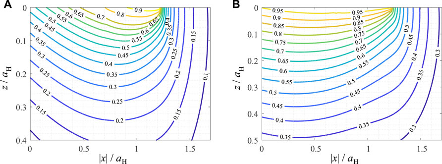
FIGURE 5. Contour line diagrams of critical plane fatigue crack initiation criteria, normalized for their maximum values, in the loading plane for the axisymmetric partial slip limiting wear profile under oscillating tangential load. (A) Smith-Watson-Topper parameter (B) Findley parameter.
7 Critical Plane Fatigue Crack Initiation Criteria for Truncated Parabolic Profiles
7.1 Scaling Laws
Although the truncated indenter also creates a pressure singularity at the edge of the flat face, the fatigue parameters remain finite in the whole simulation area, because the singularity is sufficiently weak. Note that a detailed FE-based discussion of the wear-induced stress singularities in partial slip and sliding fretting contacts has been given by Yue and Wahab (Yue and Abdel Wahab, 2014). Hence, we can introduce the same scaling as for the parabolic indenter profile,
where the characteristic scales of the fatigue initiation criteria have been introduced in Equation 26 and aH is the contact radius (or half-width) for the Hertzian contact under the given normal load. For the simulations β = 1 was used. As the results for plane and axisymmetric contact configurations, once again, are very similar, only the axisymmetric case will be shown.
7.2 Results for Axisymmetric Contact
In Figure 6 the contour line diagrams of the scaled SWT and Findley parameters are shown in the subsurface loading plane for the case of axisymmetric truncated parabolic contact. Interestingly, the results are qualitatively very similar to the unworn parabolic case. This suggests, that completely wearing off the tip of the indenter has only little influence on the formation of fatigue cracks (at least, on the macroscopic level of elastic stress fields).
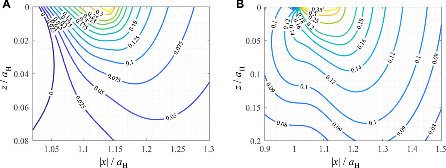
FIGURE 6. Contour line diagrams of critical plane fatigue crack initiation criteria, normalized for their characteristic scales, in the loading plane for a partial slip axisymmetric truncated parabolic contact under oscillating tangential load. (A) Smith-Watson-Topper parameter (B) Findley parameter.
The hotspot for the SWT parameter is at x = 1.14aH = a and z = 0, i.e., the contact edge, with a maximum scaled SWT parameter of 0.44 at a critical angle θ = 91.75π/180. The hotspot for the Findley parameter is at x = 1.12aH and z = 0, i.e., just on the inner side of the contact edge (like in the parabolic case), with a maximum scaled Findley parameter of 0.41 at a critical angle θ = 60.25π/180.
8 Discussion
The solutions obtained above are based on a set of simplifying assumptions to allow for a fast, comprehensive and numerically robust treatment of the problem, most prominently linear elasticity and the Amontons-Coulomb friction law. That is why the results shown are not necessarily to be understood in a quantitative sense, although they can, of course, be used also quantitatively, if the stated simplifications are met sufficiently. Plastic deformations will mainly play a role in relaxing possible stress concentrations, as (long-cycle) fatigue is usually only a relevant failure mode, if average stresses are below the yield limit, so the macroscopic fields of stress and deformation without stress concentrations are, in fact, predominantly elastic. In a similar sense, surface roughness or other tribological properties—which in the model have been subsumed in the form of a local-global “coefficient of friction”—or elastic coupling can have a bigger or smaller influence on the precise values of the critical plane parameters, depending on the system. Moreover, the analysis has been strictly “contact mechanical”, that is to say, tribological phenomena, like tribolayer formation and others, which are, without doubt, highly important when discussing the influence of fretting wear on fretting fatigue, have been neglected, as their consideration for the calculation of macroscopic, continuum mechanical fields requires a type of multi-scale simulation, which, in tribology, still is work-in-progress (Vakis et al., 2018; Meng et al., 2020).
However, the main finding of the present manuscript is of qualitative nature: On the level of the subsurface elastic stress fields, wear in partial slip fretting contacts has a significantly stronger impact on the formation of fatigue cracks in the vicinity of the contact than sliding wear—whose influence on fatigue in the described framework is basically negligible. Not only are the maximum values of the critical plane parameters severely increased for the partial slip limiting wear profile—which is logical, because of the edge singularity at the boundary of the permanent stick zone—but the “fields” of the crack initiation criteria also reach far deeper into the contact and into the subsurface material, compared to the unworn or truncated profiles with the same loading conditions. Hence, one might conclude, that it is actually the wear, which facilitates the crack nucleation in the partial slip regime of fretting contacts.
9 Conclusion
Based on a recently developed method for the fast, high-precision calculation of subsurface elastic stresses in plane and axisymmetric tangential contacts of elastically similar materials, which operates with appropriate superpositions of analytic solutions for the respective parabolic contact problem, the influence of wear profile geometry on critical plane fatigue crack initiation criteria has been analyzed on the level of the stress fields in partial slip fretting contacts. The main findings are as follows:
• the differences between plane and axisymmetric contact configurations are small for all analyzed profile geometries
• profile truncation, e.g., due to sliding wear, has almost no influence on the critical plane parameters
• for the partial slip limiting wear profile, the critical plane parameters are severely increased and reach far deeper into the contact and into the subsurface material
• the SWT parameter is generally more localized than the Findley parameter
The proposed method can also be used to analyze other fretting modes, e.g., superpositions of normal and tangential fretting oscillations.
Data Availability Statement
The original contributions presented in the study are included in the article/Supplementary Material, further inquiries can be directed to the corresponding author.
Author Contributions
The author confirms being the sole contributor of this work and has approved it for publication.
Funding
We acknowledge support by the Open Access Publication Fund of TU Berlin. This research was funded by the German Research Foundation under the project number PO 810/66‐1.
Conflict of Interest
The author declares that the research was conducted in the absence of any commercial or financial relationships that could be construed as a potential conflict of interest.
Publisher’s Note
All claims expressed in this article are solely those of the authors and do not necessarily represent those of their affiliated organizations, or those of the publisher, the editors and the reviewers. Any product that may be evaluated in this article, or claim that may be made by its manufacturer, is not guaranteed or endorsed by the publisher.
Acknowledgments
The author is grateful to Johann Kammholz for valuable discussions on the topic.
References
Antler, M. (1985). Survey of Contact Fretting in Electrical Connectors. IEEE Trans. Comp. Hybrids, Manufact. Technol. 8 (1), 87–104. doi:10.1109/tchmt.1985.1136462
Araújo, J. A., Nowell, D., and Vivacqua, R. C. (2004). The Use of Multiaxial Fatigue Models to Predict Fretting Fatigue Life of Components Subjected to Different Contact Stress Fields. Fatigue & Fract. Eng. Mater. Struct. 27 (10), 967–978.
Berthier, Y., Vincent, L., and Godet, M. (1989). Fretting Fatigue and Fretting Wear. Tribol. Int. 22 (4), 235–242. doi:10.1016/0301-679x(89)90081-9
Bhatti, N. A., and Abdel Wahab, M. (2018). Fretting Fatigue Crack Nucleation: A Review. Tribol. Int. 121, 121–138. doi:10.1016/j.triboint.2018.01.029
Cardoso, R. A., Doca, T., Néron, D., Pommier, S., and Araújo, J. A. (2019). Wear Numerical Assessment for Partial Slip Fretting Fatigue Conditions. Tribol. Int. 136, 508–523. doi:10.1016/j.triboint.2019.03.074
Cattaneo, C. (1938). Sul Contatto di due Corpore Elastici: Distribuzione degli sforzi. Rendiconti dell’ Acad. Naz. dei Lincei 27, 342–348. 434–436, 474–478.
Ciavarella, M., and Demelio, G. (2001). A Review of Analytical Aspects of Fretting Fatigue, with Extension to Damage Parameters, and Application to Dovetail Joints. Int. J. Solids Struct. 38 (10-13), 1791–1811. doi:10.1016/s0020-7683(00)00136-0
Ciavarella, M. (1998a). The Generalized Cattaneo Partial Slip Plane Contact Problem. I-Theory. Int. J. Solids Struct. 35 (18), 2349–2362. doi:10.1016/s0020-7683(97)00154-6
Ciavarella, M. (1998b). Tangential Loading of General Three-Dimensional Contacts. J. Appl. Mech. 65 (4), 998–1003. doi:10.1115/1.2791944
Collier, J. P., Mayor, M. B., Jensen, R. E., Surprenant, V. A., Surprenant, H. P., Mcnamara, J. L., et al. (1992). Mechanisms of Failure of Modular Prostheses. Clin. Orthop. Relat. Res. 285, 129–139. doi:10.1097/00003086-199212000-00017
Cruzado, A., Leen, S. B., Urchegui, M. A., and Gómez, X. (2013). Finite Element Simulation of Fretting Wear and Fatigue in Thin Steel Wires. Int. J. Fatigue 55, 7–21. doi:10.1016/j.ijfatigue.2013.04.025
Findley, W. N. (1959). A Theory for the Effect of Mean Stress on Fatigue of Metals under Combined Torsion and Axial Load or Bending. J. Eng. Indust. 81 (4), 301–305. doi:10.1115/1.4008327
Fouvry, S., Paulin, C., and Liskiewicz, T. (2007). Application of an Energy Wear Approach to Quantify Fretting Contact Durability: Introduction of a Wear Energy Capacity Concept. Tribol. Int. 40 (10-12), 1428–1440. doi:10.1016/j.triboint.2007.02.011
Gandiolle, C., and Fouvry, S. (2016). Stability of Critical Distance Approach to Predict Fretting Fatigue Cracking: a " ℓ Opt - B Opt " Concept. Int. J. Fatigue 82 (2), 199–210. doi:10.1016/j.ijfatigue.2015.07.016
Hamilton, G. M. (1983). Explicit Equations for the Stresses beneath a Sliding Spherical Contact. Proc. Institut. Mech. Eng. Part C J. Mech. Eng. Sci. 197 (1), 53–59. doi:10.1243/pime_proc_1983_197_076_02
Hills, D. A., and Nowell, D. (1994). Mechanics of Fretting Fatigue. Dordrecht: Springer Netherlands.
Hills, D. A., Sackfield, A., and Paynter, R. J. H. (2009). Simulation of Fretting Wear in Half-Plane Geometries: Part 1 – the Solution for Long Term Wear. J. Tribol. 131 (3), 031401. doi:10.1115/1.3118785
Hu, Z., Lu, W., Thouless, M. D., and Barber, J. R. (2016). Effect of Plastic Deformation on the Evolution of Wear and Local Stress Fields in Fretting. Int. J. Solids Struct. 82, 1–8. doi:10.1016/j.ijsolstr.2015.12.031
Huber, M. T. (1904). Zur Theorie der Berührung fester elastischer Körper. Ann. Phys. 319, 153–163. doi:10.1002/andp.19043190611
Jäger, J. (1993). Elastic Contact of Equal Spheres under Oblique Forces. Archive Appl. Mech. 63 (6), 402–412.
Llavori, I., Zabala, A., Urchegui, M. A., Tato, W., and Gómez, X. (2019). A Coupled Crack Initiation and Propagation Numerical Procedure for Combined Fretting Wear and Fretting Fatigue Lifetime Assessment. Theor. Appl. Fract. Mech. 101, 294–305. doi:10.1016/j.tafmec.2019.03.005
Madge, J. J., Leen, S. B., and Shipway, P. H. (2007). The Critical Role of Fretting Wear in the Analysis of Fretting Fatigue. Wear 263 (1-6), 542–551. doi:10.1016/j.wear.2006.11.021
Madge, J., Leen, S., and Shipway, P. (2008). A Combined Wear and Crack Nucleation-Propagation Methodology for Fretting Fatigue Prediction. Int. J. Fatigue 30 (9), 1509–1528. doi:10.1016/j.ijfatigue.2008.01.002
Meng, Y., Xu, J., Jin, Z., Prakash, B., and Hu, Y. (2020). A Review of Recent Advances in Tribology. Friction 8 (2), 221–300. doi:10.1007/s40544-020-0367-2
Munisamy, R. L., Hills, D. A., and Nowell, D. (1994). Static Axisymmetric Hertzian Contacts Subject to Shearing Forces. J. Appl. Mech. 61 (2), 278–283. doi:10.1115/1.2901441
Muskhelishvili, N. I. (1958). Singular Integral Equations. Editor J.R.M. Radok (Groningen: Wolters-Noordhoff Pub-Lishing). Translation of the Russian original from 1944.
Popov, V. L., Heß, M., and Willert, E. (2019). Handbook of Contact Mechanics – Exact Solutions of Axisymmetric Contact Problems. Berlin, Heidelberg: Springer-Verlag.
Popov, V. L. (2014). Analytic Solution for the Limiting Shape of Profiles Due to Fretting Wear. Sci. Rep. 4, 3749. doi:10.1038/srep03749
Shen, F., Hu, W., Voyiadjis, G. Z., and Meng, Q. (2015). Effects of Fatigue Damage and Wear on Fretting Fatigue under Partial Slip Condition. Wear 338-339, 394–405. doi:10.1016/j.wear.2015.07.012
Smith, K. N., Watson, P., and Topper, T. H. (1970). A Stress-Strain Function for the Fatigue of Metals. J. Mater. 5 (4), 767–778.
Socie, D. (1987). Multiaxial Fatigue Damage Models. J. Eng. Mater. Technol. 109 (4), 293–298. doi:10.1115/1.3225980
Szolwinski, M. P., and Farris, T. N. (1996). Mechanics of Fretting Fatigue Crack Formation. Wear 198 (1-2), 93–107. doi:10.1016/0043-1648(96)06937-2
Vakis, A. I., Yastrebov, V. A., Scheibert, J., Nicola, L., Dini, D., Minfray, C., et al. (2018). Modeling and Simulation in Tribology across Scales: An Overview. Tribol. Int. 125, 169–199. doi:10.1016/j.triboint.2018.02.005
Vingsbo, O., and Söderberg, S. (1988). On Fretting Maps. Wear 126 (2), 131–147. doi:10.1016/0043-1648(88)90134-2
Wang, S., Yue, T., WangWahab, D. M. A., and Abdel Wahab, M. (2022). Effect of Wear Debris on Fretting Fatigue Crack Initiation. Friction 10, 927–943. doi:10.1007/s40544-021-0543-z
Willert, E. (2021a). Determination Of the Stress State beneath Arbitrary Axisymmetric Tangential Contacts in Hertz-Mindlin Approximation Based on the Superposition of Solutions for parabolic Contact. [cond-mat.mtrl-sci]. Available at: https://arxiv.org/abs/2108.04617 (April 26, 2022).
Willert, E. (2021b). FFT-based Implementation of the MDR Transformations for Homogeneous and Power-Law Graded Materials. FU Mech. Eng. 19 (4), 805–816. doi:10.22190/fume210415057w
Willert, E. (2022). Explicit Analytic Solutions for the Subsurface Stress Field in Single Plane Contacts of Elastically Similar Truncated Cylinders or Wedges. ZAMM Z. für Angew. Math. Mech. submitted manuscript.
Yue, T., and Abdel Wahab, M. (2014). Finite Element Analysis of Stress Singularity in Partial Slip and Gross Sliding Regimes in Fretting Wear. Wear 321, 53–63. doi:10.1016/j.wear.2014.09.008
Zhang, T., McHugh, P. E., and Leen, S. B. (2011). Computational Study on the Effect of Contact Geometry on Fretting Behaviour. Wear 271 (9-10), 1462–1480. doi:10.1016/j.wear.2010.11.017
Keywords: fretting fatigue, critical plane approach, fretting wear, plane contacts, axisymmetric contacts, stress superposition
Citation: Willert E (2022) Influence of Wear Profile Geometry on Critical Plane Fatigue Crack Initiation Criteria in Plane and Axisymmetric Elastic Fretting Contacts. Front. Mech. Eng 8:904282. doi: 10.3389/fmech.2022.904282
Received: 25 March 2022; Accepted: 19 April 2022;
Published: 04 May 2022.
Edited by:
Ken Nakano, Yokohama National University, JapanReviewed by:
Antonio Papangelo, Politecnico di Bari, ItalyFrancesca Di Puccio, University of Pisa, Italy
Copyright © 2022 Willert. This is an open-access article distributed under the terms of the Creative Commons Attribution License (CC BY). The use, distribution or reproduction in other forums is permitted, provided the original author(s) and the copyright owner(s) are credited and that the original publication in this journal is cited, in accordance with accepted academic practice. No use, distribution or reproduction is permitted which does not comply with these terms.
*Correspondence: Emanuel Willert, ZS53aWxsZXJ0QHR1LWJlcmxpbi5kZQ==