 Johannes Altmeppen
 Heike Sommerfeld
- Institute of Aircraft Propulsion Systems, University of Stuttgart, Stuttgart, Germany
Erosion damage and particle deposition are crucial wear phenomena in gas turbine engines. As a result, compressor efficiency decreases, stability margin reduces, and maintenance cost increases. Hence, predicting these phenomena in an accurate manner is of paramount importance for a cost-efficient, safe, and sustainable operation. Erosion and particle deposition in the annulus are affected by particle transportation in the fluid and particle-wall interaction. The latter involves the particle impact, the potential damage of the surface and/or the particle, and the particle rebound. Particle rebounds are statistical in nature due to the target surface roughness, the variability in particle sizes, and superimposed effects caused by particle shapes as well as particle rotation and particle break-up during contact. Multiple studies investigated the statistics of particle rebound, providing empirical-based models for median and spread. However, modeling the particle-wall interaction and its data spread on a transparent physical basis allows separating the effect of target roughness from superimposed effects. The presented article pursues this objective by assessing the statistical spread of particle rebound data through multiple techniques and utilizing their interdependencies. It combines experimental, numerical, and analytical considerations. For the first time, coherent boundary conditions for the experimental, numerical and analytical setup allow the distinction of the effect of roughness from the integral effect of the superimposed phenomena. A sandblast test rig equipped with laser measurement equipment was used to measure particle rebound from flat titanium and stainless steel plates at different angles. The numerical setup is developed under OpenFOAM 6 using a RANS solver for transient simulations with compressible media in combination with one-way coupled particle flows. The numerical model includes the rebound spread model proposed by Altmeppen et al. combined with the quasi-analytical rebound model proposed by Bons et al. The statistical spread of particle rebound is investigated for roughness levels that are similar to the ones of deteriorated high-pressure compressor blades as discussed by Gilge et al. The measured surface roughness of the experimentally investigated targets is used as input parameters to the numerical framework. The rebound statistics obtained in the numerical simulation are compared to the rebound data measured in the experiment. Based on this study, conclusions are drawn about which part of the rebound spread is attributable to surface roughness and which is caused by superimposed effects. It was found that the effect of surface roughness as characterized by Altmeppen et al. contributes in the order of 46 % to the rebound spread for small impact angles. However, the share in spread due to roughness gradually decreases with increasing global impact angles to a level of 13 % for angles close to 90°. The remaining percentage of rebound spread is attributed to superimposing phenomena. In addition to the rolling and sliding of aspherical particles, further phenomena such as plastic deformation and erosion of the roughness peaks during contact and the associated dissipation of energy gain in importance for steeper impact angles. Therefore, the effect of surface roughness should not be neglected in numerical simulations of particle-laden flows. Modeling the superimposed phenomena which are observed to be dominating at high impact angles opens up a further field of research.
1 Introduction
The atmosphere is constantly contaminated by liquid or solid particles of different sizes, concentrations, and chemical compositions. Air-breathing engines such as industrial or airborne gas turbines are exposed to aerosol, leading to impairments in the operation (Kellersmann et al., 2018). Erosion and particle deposition along the flow path cause performance deterioration and reduction of stall margin (Richardson et al., 1979). Hence, predicting these phenomena in a reliable manner is of paramount importance for a cost-efficient and sustainable operation. For this purpose, the widely used method of numerical particle tracking requires accurate estimation of the particle rebound after impacting a surface. Particle rebounds are statistical in nature due to the alteration of particle sizes and shapes as well as their rotations, the target surface topography, and particle break-up during contact (Altmeppen et al., 2020; Sommerfeld et al., 2021). Therefore, the applied models for the particle–wall interaction in a numerical framework need to predict not only the mean particle rebound characteristics but also their natural statistical spread.
Reviewing previously published work, a clear focus on modeling only particle impacts and mean rebound coefficients becomes evident. Present modeling approaches based on physical considerations are derived either from a critical velocity approach based on the work of Brach and Dunn (1992) or a critical viscosity approach introduced by Sreedharan and Tafti (2010). Critical viscosity models concern particle softening mechanisms at high-temperature applications in the turbine section and are not reviewed in this study aiming to evaluate particle impact in the engine compressor sections. Deposition models based on critical velocity determine whether a particle sticks to the surface by comparing the actual impact velocity with a threshold velocity for the impact event below which the particle deposits.
Both model approaches share the contact mechanics of an elastic deformation based on Hertzian contact of a spherical particle with a flat surface combined with adhesion during impact (Brach and Dunn, 1992). This initial contact model has been extended in several steps to account for elastic–plastic deformation, oblique impacts, and further external forces (Kim and Dunn, 2007; Singh and Tafti, 2015; Barker et al., 2017). However, it is only valid for ideal spherical particles and requires empirical correlations (Bons et al., 2017). To address these limitations, Bons et al. (2017) derived a quasi-physical yet equally empirical and approximate interaction model. Arbitrary particle shapes are approximated as circular cylinders. Hence, particle deformation is modeled using a 1D spring approach rather than a complex 3D deformation of a sphere. The model covers elastic and plastic deformation, adhesion, and removal by shear forces.
To account for the stochastic spread of rebound data, Bons approach for modeling mean particle rebound characteristics has been further improved by Whitaker and Bons (2018) with an empirical curve fitting approach based on experimental data. Standard deviations of the coefficients of restitution vary with the considered particle and target surface combination. Hence, this approach still relies on excessive experimental testing of different particle surface combinations. Therefore, modeling approaches based on empirical correlations fail to predict the spread in the coefficients of restitution (CoR) for boundary conditions apart from the original experimental setup by up to 100 % (Bons et al., 2015). Since the basic challenge of modeling particle rebound and deposition with sufficient accuracy still remains, a physical-based access to the statistical spread is desired in this work. The scope of the presented work is to investigate the effects within the statistical spread observed during particle rebound measurements. In order to quantify different effects on the statistical spread, findings from experimental rebound measurements are complemented by a numerical investigation of the test rig. In the numerical simulation, the rebound spread model proposed by Altmeppen et al. (2020) is combined with the quasi-analytical rebound model of Bons et al. (2017). As a first step toward a general spread model, the statistical spread of particle rebound due to target roughness will be the subject of investigation. The presented study focuses on roughness levels that are similar to the ones of deteriorated high-pressure compressor blades (Gilge et al., 2019). To apply the spread model, the surface roughness of the investigated materials is measured during the experimental campaign and used as input parameters for the numerical framework. The rebound statistics obtained in the numerical simulation are then compared to rebound data measured in the experiment to conclude which portion of the rebound spread is attributable to surface roughness and which is caused by additional effects.
2 Rebound spread model based on surface roughness
When calculating particle trajectories, coefficients of restitution are used to describe the energy loss during interaction with a wall. They are defined as the magnitude of a rebound parameter divided by its corresponding impact value as shown in Figure 1.
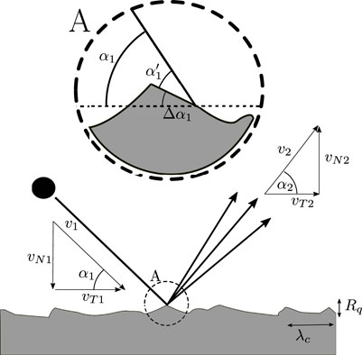
FIGURE 1. Particle impact and rebound geometries (Altmeppen et al., 2020).
To simulate the statistical spread due to surface roughness, the spread model by Altmeppen et al. (2020) was applied in this study. It is based on the approach of deriving a local impact angle
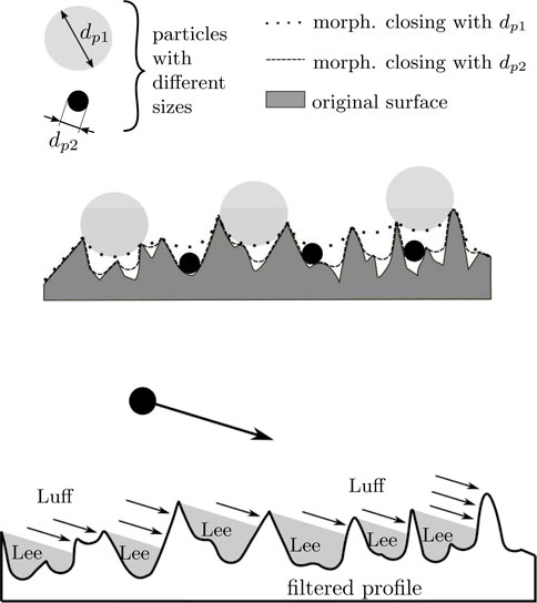
FIGURE 2. Local impact angle: (A) morphological filter with respect to the particle size; (B) particle impact on the luff sides of the surface roughness for oblique impacts (Altmeppen et al., 2020).
As the impact angles decrease in oblique impacts like in Figure 2B, the particles may not hit the lee sides in the valley of a roughness structure. As a consequence, the probability of hitting the luff side increases that causes a shift in the probability density distribution. The shifted distribution is approximated with a Weibull function:
The parameters k(α1) > 0 and λ(α1) > 0 are polynomial functions of the impact angle (Altmeppen et al., 2020).
The spread model presented by Altmeppen et al. (2020) is built upon the assumption that the slope angle distribution of the roughness profile can be approximated by a Gaussian distribution and is therefore non-skewed. To validate these assumptions and to evaluate the roughness parameter of the experiments, the surface roughness of the target material was measured. The results are presented in the next section.
3 Measurement of the surface roughness
The surface topography of several undeteriorated and eroded flat plates has been measured by confocal microscopy at the Institute of Machine Components at the University of Stuttgart. The TOOLinspect surface measuring system by Confovis with an Olympus lens 20× / NA 0,6 was used. The resolution was 200 nm in the lateral dimensions, with a precision of 0.1 nm in the measurement of the roughness height. The raw data have been processed with MountainsMap® Premium (Version 7.4). Five non-eroded flat plates have been measured for each original target material. On each plate, three measurement squares of the size 1.17 mm × 1.17 mm have been scanned, leading to 15 samples. An example of the scanned surfaces for each material can be found in Figures 3A and B. It should be noted that the plates before and after erosion are different plate samples. For the eroded materials, three plates have been investigated for each target material and operating point after eroding them with 25 g quartz. An example of these scans is shown in Figures 3C and D.
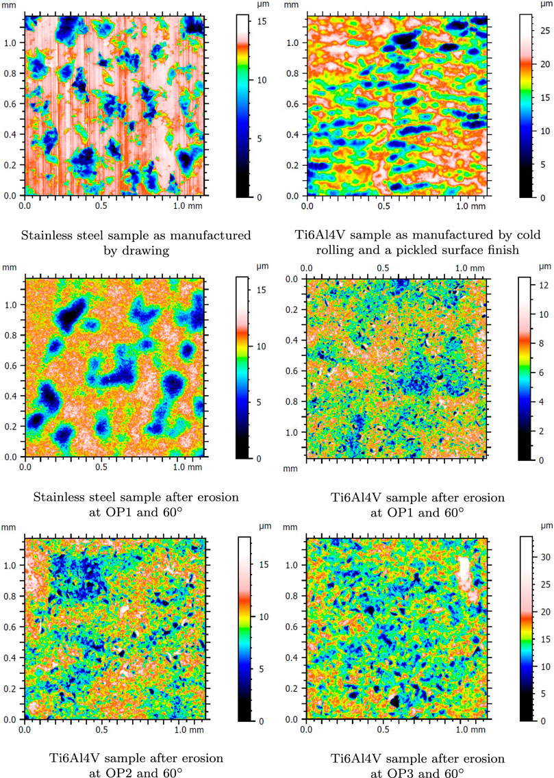
FIGURE 3. Surface topography of (A,B) uneroded and (C–F) eroded plates.
On uneroded surfaces, especially of stainless steel, an anisotropic surface profile is visible due to the manufacturing process. In addition, imperfections of various sizes are visible as holes on the surface. The anisotropic surface structure due to the manufacturing cannot be observed on the eroded plates because it is phased out during the erosion. The bigger imperfections, on the other hand, are still visible after erosion. The edges of the imperfections, however, have a smoother transition to the surrounding areas. Corresponding surface parameters can be found in Table 1, where the mean and standard deviations of all samples are summarized. The detailed protocols of the surface topography measurements of each sample can be found in Sommerfeld and Koch (2021). Since the flat plates are measured as a 2D geometry, the surface root mean square Sq and the correlation length Sal are used to replace the 1D parameters Rq and λc in the original model formulation. The roughness parameter, which is needed as model input, is therefore calculated via
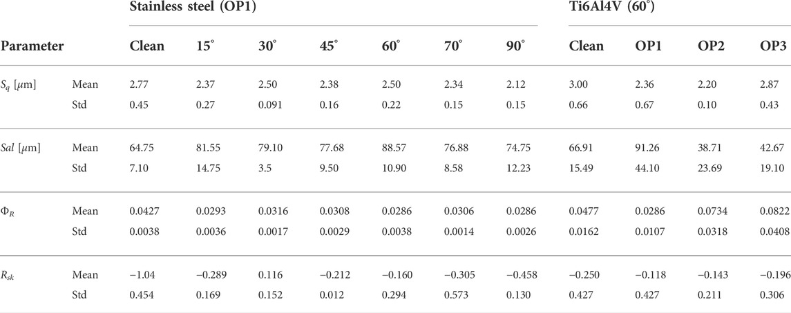
TABLE 1. Overview of surface roughness parameters of stainless steel target plates eroded at OP1 with different incidence angles and Ti6Al4V target plates for different impact velocities at 60° incidence angle.
In the presented experiments, the surface roughness parameter Sq, which represents the height of the peaks, decreases due to erosion. At the same time, the autocorrelation factor Sal rises for all 150 m/s flow cases. This leads to a reduction of the roughness parameter ΦR during erosion. However, the values of the undeteriorated and eroded plates are still in the same order of magnitude and, therefore, similar to each other. Since the rebound data were measured during the transition from undeteriorated to the eroded state, two roughness levels are used as model input to evaluate the particle rebound due to the surface roughness in the experiment: a roughness value representative of the uneroded baseline condition and the arithmetic mean of roughness values resulting from the erosion process hereinafter referred to as the eroded state.
In many performance deterioration studies (Bogard et al., 1998; Bons et al., 2001; Kellersmann et al., 2017), erosion and particle deposition are generally known to increase the surface roughness in turbomachinery components. In the experiment presented in this work, the surface roughness decreased, but the surface roughness of the new plates was already high to begin with, which is a difference from real engine blades. It is, therefore, concluded that the roughness takes an asymptotic value, which depends on the impact conditions and material combination but not on the state of the original surface roughness. If the surface roughness (as in the presented experiments) is originally higher than the asymptotic condition of erosion, it is reduced upon erosion. On the other hand, it is increased if the surface roughness has been lower beforehand, which is the case for real engine blades suffering erosion.
To investigate the proposed asymptotic surface roughness further, some additional measurements of the stainless steel targets at other impact angles have been investigated. No significant trend over the incidence angle could be observed in the surface parameters summarized in Table 1. It is, therefore, concluded that the surface roughness parameter does not depend on the impact angle. In addition, two higher impact velocities (Table 2) have been investigated for the titanium alloy targets. It could be observed that the measured surface roughness parameter rises with increasing impact velocity (Table 1). It is, therefore, concluded that the eroded surface roughness depends on the impact velocity. The corresponding surface topographies are shown in Figures 3E and F.
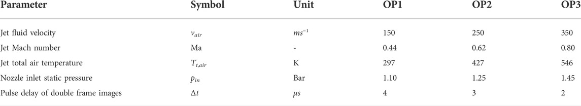
TABLE 2. Erosion test rig’s operation points.
The spread model presented by Altmeppen et al. (2020) is built upon the assumption that the slope angle distribution of the roughness profile can be approximated by a Gaussian distribution and is therefore non-skewed. The slope angle distribution relevant to the impact of individual particles is dependent on how deep a particle can penetrate the roughness structure with respect to its size. Therefore, a slope angle related particle-independent quantity, skewness Rsk of the roughness profile, has been measured for several target plates of the experiments (Table 1) to validate the assumptions. Based on a kernel density estimation of the sample, Figure 4 shows a shift in the probability distribution of skewness Rsk toward low negative values. This phenomenon results from the production methods used to manufacture the specimens (Figure 3A, B). New uneroded sample plates labeled as clean in Table 1 feature a rather high negative skewness. However, the phenomenon of roughness alteration during the experiment with respect to Rq and λc, as described earlier, causes likewise a change in skewness. The roughness tends toward a non-skewed state.
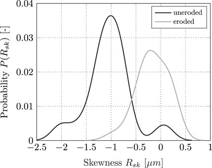
FIGURE 4. Distribution of skewness Rsk measured in the experiments for the pre- and post-erosion state.
4 Experimental investigation of particle rebound
The experimental data have been measured at a sandblast type test rig as described in Schrade and Staudacher (2014) and Schrade (2016) with a modified test chamber proposed by Hufnagel et al. (2018b). The test rig geometry and operation points in this work are summarized in Figure 5.
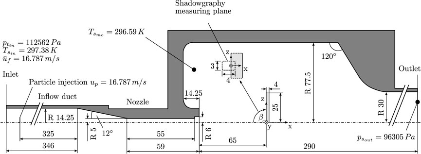
FIGURE 5. Geometry of the EVS core section as modeled in the CFD simulation including the nozzle, measuring chamber, and the boundary conditions for the operation point OP1 (based on Hufnagel et al. (2018a) and Hufnagel et al. (2018b).
The particle-laden air flow is accelerated through a nozzle. The nominal fluid velocities in the center of the jet can be set with an accuracy of ± 4.64 m/s (Schrade, 2016). Monodisperse quartz sand with a size ranging from 45 to 73 μm is used as particle material. With a particle mass of 25 g dispersed within 40 min, the particle concentration is about 3.4 ⋅ 10−7 kg/m3. Some of the rebound measurements presented in this article are part of the experimental work published previously in Sommerfeld et al. (2021). The additional impact angles of 15°, 45°, and 75° are only published here.
Flat plates of stainless steel and Ti6Al4V are used as target specimens. The mounting allows for various impact angles between 15° and 90°. Optical access allows for the examination of the particle flow by particle shadow velocimetry (PSV). Background illumination is generated by a Solo 120XT laser by New Wave to record double-frame images with a maximal repetition rate of 14 Hz. The delay between the consecutive pulses is 4 μs. For homogenous background illumination, the laser light is scattered through an optical diffusor. Images are recorded with an ImagerProX 2M camera. It is mounted on a long-distance microscope and focused on the x-z plane of the particle jet. The field of view is 4.2 mm × 3.0 mm. A ParticleMaster System by LaVision (Goettingen, Germany) is operated for image recording and scaling. Post-processing of the PSV images is performed using an in-house code described in previous work by Sommerfeld et al. (2021). Post-processing of the images leads to the particle vector field in the measurement area. The particles are classified as approaching, rebounding, or secondary particles as presented in Sommerfeld et al. (2021). The distributions of the approaching and rebounding particles are used in a field average technique to calculate the coefficients of restitution (as in Eq. 1). Therefore, the median values of the underlying distributions are used. The distribution of the statistical spread is obtained by dividing the individual rebound values by the median impact value. The statistical spread needs to be evaluated with respect to the measurement uncertainty, which may also contribute to a statistical spread in the measurement data.
4.1 Measurement uncertainty analysis
The particle size algorithm is validated using a high precision calibration plate with circles of known particle diameters between 10 and 200 μm. It was found to be accurate within ± 1.7 μm with an image resolution of 1 pixel = 7.2 μm2. The system can detect particles down to 20 μm (Sommerfeld et al. (2021)). The maximum and mean uncertainty ϵv of an individual particle velocity vector was calculated to be ± 1.22 m/s and ± 0.43 m/s with Gaussian error propagation (Sommerfeld et al., 2021). The measured particle number for statistical evaluation is biased with two systematic measurement errors, namely, depth of field (DoF) and border correction (BC), that are corrected with a weight parameter for the particle number as presented in Sommerfeld et al. (2021).
To account for stochastic errors, each experiment at a certain operation point and angle is repeated three times. Afterward, all measured particles from the three experiments are combined for statistical evaluation. To quantify the confidence intervals of the statistical results, a bootstrapping technique is used. Bootstrapping is a method of random resampling with replacement. It allows for a quantitative evaluation of the confidence interval for the statistics of a finite sample size N (see Efron and Tibshirani (1986)). A large number B of bootstrapping resamples of the same size N are randomly sampled out of the original data set with N particles to calculate the confidence intervals. The number of bootstrap data samples was set to be B = 100,000 following Efron and Tibshirani (1986). An example of the confidence intervals for the median of the absolute coefficient of restitution as a function of the impact angle is shown in Figure 6A. The natural statistical spread of the absolute coefficient of restitution is represented by the 16% and 84% percentiles of the underlying distribution and their corresponding 99% confidence intervals. The median 99% confidence intervals for all measured coefficients CoRv, CoRN, CoRT, and CoRα are summarized in Table 3. The values are averaged over both target materials since the uncertainty values were found to be similar for both material combinations in this study.
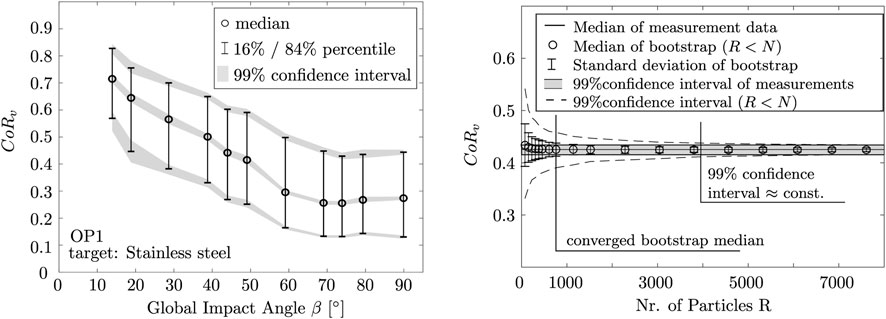
FIGURE 6. Measurement uncertainty: (A) 99% confidence intervals for the distribution’s median CoRv and its percentile over the impact angle; (B) usage of the bootstrapping technique to check for a significant sample size (Ti6Al4V, OP1, 50°).
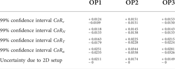
TABLE 3. Summary of dominant measurement uncertainties.
To check for a statistically significant sample size, bootstrapping with R < N was used to evaluate the number of particles needed for the coefficients of restitution to converge. An example of this calculation is presented in Figure 6B. It was found that about 1,000 measured particles are needed for a converged median within the 99% confidence interval. To yield a narrow confidence interval, over 4,000 particles are recommended.
Another measurement uncertainty arises by neglecting the particle direction in the third dimension after impact, which is not measurable with this experimental setup. In the study by Eroglu and Tabakoff (1991), the difference in the tangential coefficient of restitution CoRT for a 2D vs. 3D measurement setup was measured, and it was concluded that the results did not differ significantly. Therefore, the simpler 2D measurement setup is used in this study. To approximate the thereby introduced uncertainty, the normal configuration (α = 90°) is examined in its measured 2D configuration. The setup is symmetric to the x-z and x-y planes. This can be used to approximate the measurement uncertainty in the third dimension. The median deviation between the measured absolute velocity v1 and the normal velocity vN1 is found to be 0.08 m/s for OP3 which shows the highest spread in the measurement data. Assuming the same values for the third dimension leads to an uncertainty of + 0.053% for the approaching particle velocities. For the rebounding particles, the median deviation of 3.97 m/s is considerably higher, leading to an average uncertainty of + 7.2%. The uncertainties propagate into the rebound characteristics. The resulting uncertainty in the coefficients of restitution is non-symmetric because the absolute velocity can be equal to or higher than the measured velocity in 2D. The uncertainty may, therefore, lead to an underprediction for the absolute coefficient of restitution but may not lead to an overprediction. With Gaussian error propagation, the approximated median uncertainty
is found to be + 0.015 m/s for OP3. Due to the different order of magnitudes, the uncertainty ϵv1 is neglected. This result is in the same order of magnitude as the measured deviations in Eroglu and Tabakoff (1991) and is therefore believed to be valid. The results for all operation points are summarized in Table 3.
5 Numerical investigation
5.1 Numerical grid
The detailed geometry of the experimental test bench was adjusted in the simulation to fit the CFD techniques (Figure 5). A multiblock-hex-dominant grid is generated using the meshing software snappyHexMesh (Greenshields, 2018). A combination of H-type and O-type grid blocks has been chosen to resolve the inlet and nozzle sections up to the probe plate and thus account for secondary flow structures, such as the corner vortex. A high mesh resolution down to the viscous sublayer is desired for all walls. A model based on Spalding’s law is applied since a fully resolved boundary layer and a first cell center positioned in the viscous sub-region cannot be ensured for all boundary patches. It is capable of fitting the relation u+ = y+ in the viscous layer and u+ = Ey+/κ in the log-law region. A grid refinement study has been conducted to guarantee grid-independent results for the fluid and particle solution. It resulted in a mesh with 6,940,756 elements. The achieved results are of high accuracy but feature the lowest possible computational effort.
5.2 Numerical setup
Numerical simulations are performed with the open-source software OpenFOAM 6. The RANS solver reactingParcelFoam has been used to discretize the fluid in a Eulerian and particle phase in the Lagrangian framework. It is capable of transient simulations with compressible media in combination with one-way or two-way coupled particle flows. Based on the particle concentration in the experiments, it is concluded that the volume fraction of the injected particles is low
The sum of acting forces is composed of the drag force
The drag force experienced by a single particle of diameter dp is described using the drag coefficient CD:
Introducing the mass-point approach and the kinematic viscosity ν, the particle Reynolds number Rep is used according to Haider and Levenspiel (1989) to develop an empirical correlation for the drag coefficient CD. The implemented correlation is valid for Rep < 2.6 ⋅ 105 which is satisfied in this work.
The shape factor ΦD is introduced to take into account the non-sphericity of real particles. It is used to determine the model coefficients A − D.
Wadell (1935) prescribes the shape factor ΦD as
the ratio between the surface area of a perfect sphere Sk of the same volume as the particle and the actual particle’s surface area Sp. The shape factor ΦD is set to 0.8, assuming a particle shape between an isometric polyhedron and a sphere based on Haider and Levenspiel (1989). This assumption has been validated by a 2D shape analysis (Pentland, 1927) of a particle sample from the experiment. The numerical setup was adjusted to ensure a particle size distribution that corresponds to the distribution measured in the experiment (Figure 7A).
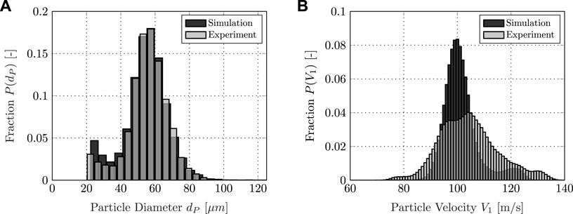
FIGURE 7. Particle boundary conditions: (A) diameter distribution of particles injected into the test rig; (B) velocity distribution of the impacting particles.
Turbulence is modeled using the Menter-SST-k-ω-model by Menter and Esch (2001) with updated coefficients (Menter et al., 2003). A turbulence intensity of I = 5 % is assumed in the inlet plane. Gradient, divergence, and Laplacian terms are solved by applying second-order schemes, while a transient first-order scheme is used for time derivative terms. The time step is continuously adjusted to not exceed a maximum CFL number of 15. OpenFOAM uses a particle tracking methodology based on Macpherson et al. (2009) but with an updated barycentric tracking (Bainbridge, 2019). A maximum particle CFL number of one is not exceeded. A discrete random walk model is introduced to consider the influence of small-scale turbulent flow structures on the individual particle trajectory that are not resolved by the RANS method. Considering the underlying particle size distribution and the fluid mechanical boundary conditions determined in the experiment and summarized in Figure 5, the numerical simulation is capable of reproducing the probability distribution of the absolute particle impact velocity V1 measured in the experiment in terms of mean value with sufficient accuracy (Figure 7B). Minor deviations occur in the variance of the distribution, which can be attributed to effects such as the numerical uncertainty of the RANS method and other necessary assumptions in the modeling such as applying the same representative shape factor for every particle.
5.3 Particle–wall interaction
The quasi-physical interaction model by Bons et al. combined with extensions by Whitaker et al. is implemented to model particle–wall interaction and to estimate if a particle deposits on a surface or rebounds upon impact (Bons et al., 2017; Whitaker and Bons, 2018; Altmeppen et al., 2020). It has been further improved with the spread model described in Section 2 to account for statistical spread due to target surface roughness. The target plate and particle features are set to match the experimental setup described in Section 4.
To account for a varying roughness over the experiment and its influence on the time-averaged rebound spread, two levels of roughness are examined in the numerical investigation: a mean roughness of eroded plates with Sq ≈ Rq = 2.57 μm Sal ≈ λc = 71.90 μm and a dimensionless roughness parameter of ΦR = 0.036, indicated in the following by the expression eroded, as well as a roughness profile with Sq ≈ Rq = 2.77 μm Sal ≈ λc = 64.78 μm and ΦR = 0.043, representing the uneroded surface of a sample plate before the experiment. It should be noted that the numerical model requires 1D roughness parameters as input. Accordingly, they are approximated based on the equivalent 2D quantities from the experiment. For simplicity, the following numerical and experimental results are labeled using the 1D notation.
Based on findings gained in Section 3, roughness profiles representing the whole experimental process have been generated artificially using the methods outlined by Garcia and Stoll (1984). The procedure creates roughness profiles that fulfill Gaussian statistics. They are processed using methods described in Altmeppen et al. (2020) to gain a kernel density estimate and, subsequently, a normal Gaussian distribution function of possible impact angles per particle diameter.
Altmeppen et al. (2020) introduced the Kullback–Leibler divergence to evaluate the quality of the approximation. Values of DKL close to zero indicate a sufficiently accurate approximation.
Figure 8 shows the generated roughness profiles and an example of the kernel density estimation and its corresponding normal Gaussian approximation. With a median value of DKL,median = 0.0046 for all uneroded and DKL,median = 0.0881 for all eroded roughness distributions, the normal Gaussian distributions have achieved sufficient accuracy and can be used as an approximation in the numerical simulation.
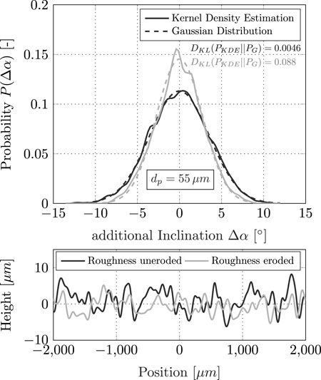
FIGURE 8. Roughness estimate of sample plates representing an uneroded surface
6 Results and discussion
6.1 Influence of the surrounding fluid flow and the measurement method
The particle shadow velocimetry method described in Section 4 for determining the particle velocity and consequently the CoR is based on one crucial assumption: the deviation of the particle vector between the point of measurement and the plate contact point due to the carrier fluid is negligible. Whether this assumption is valid and the particle vector does not change significantly until impacting the plate or after the rebound, however, must be proven and can be analyzed with the provided numerical simulation. Therefore, the CoR statistics are determined for the numerical simulation both with the post-processing routines on which the PSV is based and directly on the plate during rebound. The first method is further referred to as the window method, as it evaluates the state of motion of individual particles within a measurement window in front of the sample plate (Figure 5), while the second is labeled as the plate method. It evaluates the state of motion at the moment of impact on the sample plate. The influence of the measurement method and subsequently the surrounding fluid flow on the CoR and its spread is shown in Figure 9 for the plate inclination angle β = 45° and uneroded roughness setup.
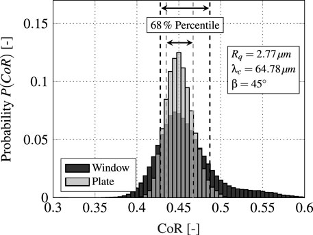
FIGURE 9. Influence of the measurement method and the surrounding fluid flow on the CoR within the numerical simulation.
The two evaluation methods yield approximately the same CoR median. However, the window approach produces an 85 % increase in the spread for the illustrated 68 % percentile. To investigate the cause of this deviation in the spread, the near-wall particle behavior is discussed in Figure 10. A separate numerical analysis with a CoR artificially set to a fixed value of one has been conducted to isolate the effect of the flow field. The trajectories of several representative particles and their temporal kinetic energy k are plotted for several plate inclination angles β. The sample shows that the particles do not deviate significantly from their motion vector within the analysis window. However, their kinetic energy varies within the track. Depending on the plate angle and the underlying surrounding fluid flow, particles are decelerated on their path to the plate or accelerated after the rebound. The deviations of the kinetic energy within the evaluation window increase as the plate inclination increases and thus the pressure gradient becomes larger. Although the maximum possible energy loss in this study at β = 90° is greater than 50 %, the energy variation for more than 70 % of all particles is less than 20 % (Figure 11).
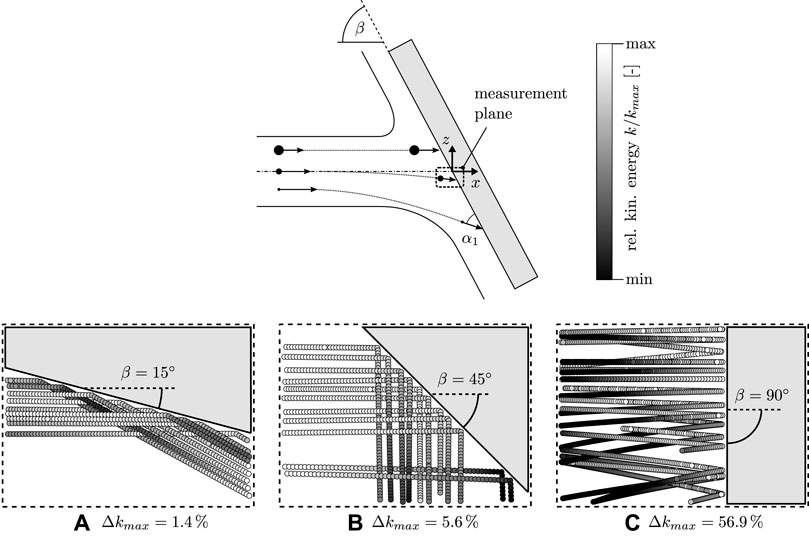
FIGURE 10. Deviation of the particle’s kinetic energy within the measurement plane for the numerical simulation.
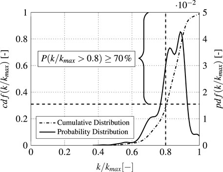
FIGURE 11. Cumulative and probability distribution of the kinetic energy deviation for all particles within the measurement plane for plate inclination angle β = 90°.
The maximum energy variation within the measurement window decreases rapidly for shallower impact angles β < 90°. Using the same experimental setup, Sommerfeld et al. (2021) stated that the deviation of the particle vector between the point of measurement and the contact point due to the carrier fluid can be neglected as particle sizes are chosen in order to yield high Stokes numbers (≫ 10). The aforementioned finding supports this assumption. A large particle relaxation time (Tropea et al., 2007) combined with a maximum possible distance from a measurement point to the plate of only about 2 mm allows neglecting the influence of the surrounding fluid flow.
Thus, the discrepancy in the coefficients of restitution spread illustrated in Figure 9 must be attributed to the field average technique introduced in Section 4. Unlike in the numerical simulation, the velocity vectors of impacting and rebounding particles cannot be assigned to each other in the experiment on a one-to-one basis. Instead, the CoR and its distribution of statistical spread are accessed by dividing the individual rebound values by the median impact value. As a result, for some particles, the CoR is overestimated by dividing individual rebound velocities by an impact velocity that is too low. For others, the CoR is conversely underestimated. The implemented post-processing method contributes to a statistical spread in the measurement data.
In the subsequent analysis of numerical and experimental rebound data, this effect is taken into account by processing the numerical results with the same field averaging technique.
6.2 Influence of the impact velocity distribution and surface roughness
Figures 12A–C show the CoR data resulting from the experiment and numerical simulation, respectively. In the simulation, eroded ΦR = 0.036 and uneroded ΦR = 0.043 roughness statistics have been applied. In addition, the analytical solution of the Bons model for a mean particle diameter dp = 40 μm and a mean total impact velocity of V1 = 100 m/s is plotted as a reference. Both the analytical Bons model as well as the median values derived from the numerical simulation match the median of the experimentally determined CoRN data. The model approaches overestimate the tangential component CoRT at high plate inclination β and impact angles α1.
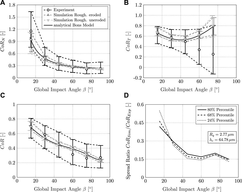
FIGURE 12. Experimental and numerical data: (A) CoRN, (B) CoRT, and (C) CoR over the global impact angle (including 68% percentile) using the PSV post-processing routine; (D) ratio of CoR spread range measured in the experiment and spread obtained in the numerical simulation while applying the spread model for the uneroded roughness
The imposed variation of the surface topography and the imposed statistical distribution of the impact velocity V1 (Figure 7) lead to a spread in the numerically obtained CoR data. The spread in the numerical data is of the same order of magnitude as observed experimentally. However, the experimentally observed spread exceeds the numerically predicted spread significantly. This is attributed to superimposed phenomena discussed later in this article.
To differentiate the effect of the imposed surface topography from the imposed velocity distribution, a separate pure analytical study has been conducted using the Bons model. The isolated effect of the difference in velocity distributions shown in Figure 7 is demonstrated assuming a perfectly smooth surface. Subsequently, this effect is investigated for the measured roughness of the test specimen using the surface model according to Altmeppen et al. (2020). By applying the Bons model directly to the velocity distributions from numerics and experiment all fluid mechanical influences from the CFD are eliminated.
Figure 13A depicts the preceding for a plate inclination β = 45°. For the case of the smooth surface, the difference in velocity distribution shown in Figure 7 directly translates into the spread in the rebound coefficient. This is superimposed by the roughness effect in a dominant way. Although the two velocity distributions vary significantly, they both lead to nearly identical spread distributions. Repeated investigations reveal a dependence on impact angle (Figure 13B). At low impact angles, the deviation in the spread is less than 15% (Figure 13B; △). For steeper inclination, the deviation decreases steadily and converges to zero for impact angles close to 90°. By comparing the purely analytical solution for a smooth surface with a spread obtained using a rough surface (Figure 13B; △, O), the influence of the velocity distribution V1 on the spread can be characterized. It is quantified as 16−42%, depending on the underlying velocity profile V1. The remaining fraction can, therefore, be attributed to the influence of the surface topography.
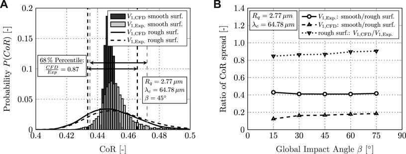
FIGURE 13. Effects on the CoR spread range: (A) influence of the impact velocity distribution on the CoR; (B) ratio of CoR spread range (68% percentile) generated analytically by applying a perfectly smooth and a rough surface for 1) the experimental velocity distribution V1, 2) the numerical velocity distribution V1, and 3) comparison of CoR spread range generated each for a rough surface but different velocity distributions V1.
With these findings in mind, Figures 12A–C can be analyzed in more detail. The variation in roughness over the experiment has a very small effect on the predicted median and spread of the CoR. Hence, it is sufficient to discuss further only one of the two roughness profiles. Setting the spread observed in the experiment and numerics in relation to each other (Figure 12D), the effect of roughness on the total spread is derived. Depending on the plate inclination and thus global impact angle, the numerical simulation reproduces 15%–55% of the total spread measured in the experiment (Figure 12D). Considering an approximate 16% share in spread due to the impact velocity distribution in the numerical simulation, the resulting share in spread due to roughness as characterized by Altmeppen et al. (2020) is in the order of 46% for small impact angles. In this region, the effect of surface roughness is significant for a particle’s individual rebound.
It should be noted that the measurement data and the numerical simulation predict CoRN > 1 for small impact angles. At low impact angles α1, the shadow effect discussed by (Altmeppen et al., 2020) leads to a high probability of a significantly positive Δα. The impacting particles are deflected at the rough surface and the high tangential component VT1 of the particle velocity is converted into a high normal fraction VN2. Therefore, CoRN reaches values higher than unity and has a substantial share in spread due to roughness. The remaining portion of the spread can thus be attributed to superimposed effects such as rolling and sliding of the particles. A similar phenomenon can be expected for the tangential CoRT for impact angles α1 close to 90°. The high normal velocity VN1 is converted into a high tangential fraction VT2. In addition, particles can be deflected in both positive and negative directions, depending on the impact location. This effect leads to a profound spread in the tangential CoR observed experimentally and in the simulation. A switch in the sign of the tangential velocity from inbound to outbound results in negative CoRT values. However, the share in spread due to roughness gradually decreases with increasing global impact angles to a level of 13% for α1 close to 90°. This leads to the conclusion that in this region, other phenomena play a decisive role that superimpose the influence of roughness to a greater extent than for shallow angles. In addition to the rolling and sliding of aspherical particles, further phenomena such as plastic deformation and erosion of the roughness peaks during contact and the associated dissipation of energy gain in importance for steeper impact angles and superimpose the effect of surface roughness. Investigation of these phenomena will be the aim of further research.
7 Conclusion
Experimental and numerical investigations into the effect of surface roughness on particle rebound and its statistical spread have been conducted. Roughness levels have been investigated that are similar to those of deteriorated high-pressure compressor blades (Gilge et al., 2019). A sandblast test rig equipped with laser measurement equipment was used to measure particle rebound from flat titanium and stainless steel plates at different angles. Findings from experimental rebound measurements have been complemented by a numerical investigation of the test rig. In the numerical simulation, the rebound spread model proposed by Altmeppen et al. (2020) has been combined with the quasi-analytical rebound model of Bons et al. (2017). To assess the statistical spread on a physical basis, the surface roughness of the investigated targets was measured and characterized by a dimensionless roughness parameter ΦR. Based on literature data and the conducted measurements, it was concluded that the roughness takes an asymptotic value, which depends on the impact conditions and material combination but not on the state of the original surface roughness. If the surface roughness is originally higher than the asymptotic condition of erosion, it is reduced upon erosion. On the other hand, it is increased if the surface roughness has been lower beforehand. Additional measurements revealed that the surface roughness parameter does not depend on the impact angle but on the impact velocity. Furthermore, the phenomenon of roughness alteration during the experiment with respect to Rq and λc causes a change in skewness. The roughness tends toward a non-skewed state. Therefore, a major assumption within the spread model presented by Altmeppen et al. (2020) could be validated. The height and slope angle distribution of a roughness profile under erosion can be approximated by a Gaussian distribution and is therefore non-skewed. The results of the measurement have been used as input parameters to the numerical framework.
Using numerical techniques, the contribution of the measurement method and post-processing routines to the statistical spread in the measurement data has been determined. The field average technique widely used in CoR determination has been found to cause an overestimation of spread by up to a factor of two. Thus, the statistical spread in experiments and numerics has to be evaluated with respect to this measurement uncertainty.
Connecting the possible variation of local impact angles based on the surface topography with the Bons model induces a significant spread in the CoR data. Not only the median value derived from the numerical simulation matches the median CoR data determined experimentally but also the spread in the numerical data is of the same order of magnitude.
Based on several numerical studies, the individual contributions of different effects to the spread were determined. By comparing the spread range in CoR data within a purely analytical solution for a smooth surface with a spread obtained using a rough surface solution, the influence of a varying velocity distribution V1 on the spread has been characterized. Once the effect of surface roughness is introduced, the variance within the velocity distribution has only a subordinate impact as long as the median value of the impact velocity distribution is constant. It is superimposed by the roughness effect. At low impact angles, the deviation in the spread is less than 15 %. For steeper inclination, the deviation decreases steadily and converges to zero for impact angles close to 90°.
According to these findings, rebound statistics obtained in the numerical simulation have been compared to rebound data measured in the experiment. Considering an approximate 16 % share in spread due to the impact velocity distribution, the resulting share in spread due to roughness common for turbomachinery applications has been found to be in the order of 46% for small impact angles. In this region, the effect of surface roughness as characterized by Altmeppen et al. (2020) is significant for a particle’s individual rebound behavior. The remaining portion of the spread can thus be attributed to superimposed effects such as the rolling and sliding of the particles. A similar phenomenon can be expected in the tangential CoR for impact angles α1 close to 90°. However, the share in spread due to roughness gradually decreases with increasing global impact angles to a level of 13% for α1 close to 90°. In this region, other phenomena play a decisive role that superimposes the influence of roughness to a greater extent than for shallow angles. In addition to the rolling and sliding of aspherical particles, phenomena such as plastic deformation and erosion of the roughness peaks during contact and the associated dissipation of energy might gain in importance for steeper impact angles and superimpose the effect of surface roughness.
These findings lead to the conclusion that the effect of surface roughness is significant for a particle’s individual rebound. This is especially relevant for shallow impact angles. Therefore, the effect of surface roughness should not be neglected in numerical simulations of particle-laden flows in turbomachinery applications. Modeling the superimposed phenomena which are observed to be dominating at high impact angles opens up a further field of research.
Data availability statement
The raw data supporting the conclusions of this article will be made available by the authors, without undue reservation.
Author contributions
JA: writing—original draft, conceptualization, and numerical investigation; HS: writing—original draft, conceptualization, and experimental investigation; CK: writing—review and editing, validation, and supervision; SS: writing—review and editing, validation, supervision, and funding acquisition.
Funding
The project on which this report is based was funded by the Deutsche Forschungsgemeinschaft (DFG, German Research Foundation) under the funding number 420603919 and by the German Federal Ministry of Education and Research (BMBF) under the funding number 01IS17051. The author is responsible for the content of this publication.
Conflict of interest
The authors declare that the research was conducted in the absence of any commercial or financial relationships that could be construed as a potential conflict of interest.
Publisher’s note
All claims expressed in this article are solely those of the authors and do not necessarily represent those of their affiliated organizations, or those of the publisher, the editors, and the reviewers. Any product that may be evaluated in this article, or claim that may be made by its manufacturer, is not guaranteed or endorsed by the publisher.
References
Altmeppen, J., Sommerfeld, H., Koch, C., and Staudacher, S. (2020). An analytical approach to estimate the effect of surface roughness on particle rebound. J. Glob. Power Propuls. Soc. 4, 27–37. doi:10.33737/jgpps/118624
Bainbridge, W. (2019). O. b. tracking. Available at: https://cfd.direct/openfoam/free-software/barycentric-tracking/(Accessed November 6, 2019).
Barker, B., Hsu, K., Varney, B., Boulanger, A., Hutchinson, J., and Ng, W. (2017). “An experiment-based sticking model for heated sand,” in ASME turbo expo 2017: Turbine technical conference and exposition (New York, NY, USA: American Society of Mechanical Engineers (ASME)), V02DT48A014. doi:10.1115/GT2017-64421
Bogard, D. G., Schmidt, D. L., and Tabbita, M. (1998). Characterization and laboratory simulation of turbine airfoil surface roughness and associated heat transfer. J. Turbomach. 120, 337–342. doi:10.1115/1.2841411
Bons, J. P., Blunt, R., and Whitaker, S. (2015). “A comparison of techniques for particle rebound measurement in gas turbine applications,” in ASME turbo expo 2015: Turbine technical conference and exposition (New York, NY, USA: American Society of Mechanical Engineers (ASME)), V001T01A029. doi:10.1115/GT2015-43766
Bons, J., Prenter, R., and Whitaker, S. (2017). A simple physics-based model for particle rebound and deposition in turbomachinery. J. Turbomach. 139. doi:10.1115/1.4035921
Bons, J., Taylor, R., McClain, S., and Rivir, R. (2001). The many faces of turbine surface roughness. J. Turbomach. 123, 739–748. doi:10.1115/1.1400115
Brach, R. M., and Dunn, P. F. (1992). A mathematical model of the impact and adhesion of microsphers. Aerosol Sci. Technol. 16, 51–64. doi:10.1080/02786829208959537
Efron, B., and Tibshirani, R. (1986). Bootstrap methods for standard errors, confidence intervals, and other measures of statistical accuracy. Stat. Sci. 1986, 54–75. doi:10.1214/ss/1177013815
Eroglu, H., and Tabakoff, W. (1991). “3-d ldv measurements of particle rebound characteristics,” in 29th aerospace sciences meeting, 11. doi:10.2514/6.1991-11
Garcia, N., and Stoll, E. (1984). Monte Carlo calculation for electromagnetic-wave scattering from random rough surfaces. Phys. Rev. Lett. 52, 1798–1801. doi:10.1103/PhysRevLett.52.1798
Gilge, P., Kellersmann, A., Friedrichs, J., and Seume, J. R. (2019). Surface roughness of real operationally used compressor blade and blisk. Proc. Institution Mech. Eng. Part G J. Aerosp. Eng. 233, 5321–5330. doi:10.1177/0954410019843438
Greenshields, C. (2018). Mesh generation with snappyhexmesh. Available at: https://cfd.direct/openfoam/user-guide/v6-snappyHexMesh/#x26-1930005.4 (Accessed May 12, 2022).
Haider, A., and Levenspiel, O. (1989). Drag coefficient and terminal velocity of spherical and nonspherical particles. Powder Technol. 1, 63–70. doi:10.1016/0032-5910(89)80008-7
Hufnagel, M., Staudacher, S., and Koch, C. (2018a). Experimental and numerical investigation of the mechanical and aerodynamic particle size effect in high-speed erosive flows. J. Eng. Gas Turbines Power 140. doi:10.1115/1.4039830
Hufnagel, M., Werner-Spatz, C., Koch, C., and Staudacher, S. (2018b). High-speed shadowgraphy measurements of an erosive particle-laden jet under high-pressure compressor conditions. J. Eng. Gas. Turbine. Power 140, 012604. doi:10.1115/1.4037689
Kellersmann, A., Reitz, G., and Friedrichs, J. (2018). Deterioration effects of coupled blisk blades. J. Glob. Power Propuls. Soc. 2, CKB8N6. doi:10.22261/JGPPS.CKB8N6
Kellersmann, A., Weiler, S., Bode, C., Friedrichs, J., Städing, J., and Ramm, G. (2017). “Surface roughness impact on low-pressure turbine performance due to operational deterioration,” in ASME turbo expo: Power for land, sea, and air (New York, NY, USA: American Society of Mechanical Engineers Digital Collection), V02DT48A012. doi:10.1115/GT2017-64180
Kim, O., and Dunn, P. (2007). A microsphere-surface impact model for implementation in computational fluid dynamics. J. Aerosol Sci. 38, 532–549. doi:10.1016/j.jaerosci.2007.03.006
Macpherson, G. B., Nordin, N., and Weller, H. G. (2009). Particle tracking in unstructured, arbitrary polyhedral meshes for use in cfd and molecular dynamics. Commun. Numer. Methods Eng. 3, 263–273. doi:10.1002/cnm.1128
Menter, F. R., and Esch, T. (2001). “Elements of industrial heat transfer prediction,” in 16th Brazilian congress of mechanical engineering (COBEM).
Menter, F. R., Kuntz, M., and Langtry, R. (2003). Ten years of industrial experience with the sst turbulence model. Turbul. heat mass Transf. 1, 625–632.
Pentland, A. (1927). A method of measuring the angularity of sands. Proc. Trans. Roy. Soc. Can. (ser. 3) 21.
Richardson, J., Sallee, G., and Smakula, F. (1979). “Causes of high pressure compressor deterioration in service,” in 15th Joint Propulsion Conference. doi:10.2514/6.1979-1234
Schrade, M., and Staudacher, S. (2014). High-speed test rig for the investigation of erosion damage of axial compressor blades.
Schrade, M. (2016). Untersuchungen zum Einfluss des Strahlverschleißes auf Hochdruckverdichterschaufeln von Turboflugtriebwerken. München, Germany: Verlag Dr. Hut.
Singh, S., and Tafti, D. (2015). Particle deposition model for particulate flows at high temperatures in gas turbine components. Int. J. Heat Fluid Flow 52, 72–83. doi:10.1016/j.ijheatfluidflow.2014.11.008
[Dataset] Sommerfeld, H., and Koch, C. (2021). Data for: High velocity measurements of particle rebound characteristics under erosive conditions of high pressure compressors. doi:10.18419/darus-2025
Sommerfeld, H., Koch, C., Schwarz, A., and Beck, A. (2021). High velocity measurements of particle rebound characteristics under erosive conditions of high pressure compressors. Wear 470-471, 203626. doi:10.1016/j.wear.2021.203626
Sreedharan, S., and Tafti, D. (2010). “Composition dependent model for the prediction of syngas ash deposition with application to a leading edge turbine vane,” in Turbo expo: Power for land, sea, and air (New York, NY, USA: American Society of Mechanical Engineers (ASME)), Vol. 55232, 615–626. doi:10.1115/GT2010-23655
Tropea, C., Yarin, A. L., and Foss, J. F. (2007). Springer handbook of experimental fluid mechanics. Berlin Heidelberg: Springer-Verlag.
Wadell, H. (1935). Volume, shape and roundness of quartz particles. J. Geol. 1, 250–280. doi:10.1086/624298
Keywords: surface roughness, erosion, compressor deterioration, fouling, particle rebound, analytical model
Citation: Altmeppen J, Sommerfeld H, Koch C and Staudacher S (2022) Experimental and numerical investigation into the effect of surface roughness on particle rebound. Front. Mech. Eng 8:918708. doi: 10.3389/fmech.2022.918708
Received: 12 April 2022; Accepted: 25 August 2022;
Published: 07 October 2022.
Edited by:
Adel Ghenaiet, University of Science and Technology Houari Boumediene, AlgeriaReviewed by:
Jeffrey Bons, The Ohio State University, United StatesPaolo Venturini, Sapienza University of Rome, Italy
Copyright © 2022 Altmeppen, Sommerfeld, Koch and Staudacher. This is an open-access article distributed under the terms of the Creative Commons Attribution License (CC BY). The use, distribution or reproduction in other forums is permitted, provided the original author(s) and the copyright owner(s) are credited and that the original publication in this journal is cited, in accordance with accepted academic practice. No use, distribution or reproduction is permitted which does not comply with these terms.
*Correspondence: Johannes Altmeppen, am9oYW5uZXMuYWx0bWVwcGVuQGlsYS51bmktc3R1dHRnYXJ0LmRl