 M. Muchammad1*
 Daniel Dwi Putra Wibowo1
 Mohammad Tauviqirrahman1
 Budi Setiyana1,2Eflita Yohana1
 J. Jamari1
- 1Laboratory for Engineering Design and Tribology, Department of Mechanical Engineering, Faculty of Engineering, Diponegoro University, Semarang, Indonesia
- 2Laboratory for Surface Technology and Tribology, Faculty of Engineering Technology, University of Twente, Enschede, Netherlands
A bearing is an element that maintains the relative motion between two components in industrial machines, while a journal bearing is often used to maintain the shaft constantly rotating on its axis. Generally, an increase in journal bearings’ performance is essential for industrial development. An increase in engine speed affects the distribution of pressure, temperature, and acoustics. Scientists have proposed various methods to analyze pressure distribution, load-bearing capacity, acoustic power, friction force, cavitation, and elastic phenomena to improve journal bearings’ tribological performance. Therefore, this study aimed to discuss the differences in the flow type modeling between smooth and multistep journal bearings. The results indicated that tribological performance increased significantly in turbulent flow in smooth and multistep journal bearings. The simulation results showed a difference between k-epsilon turbulent flow modeling and k-omega flow modeling.
1 Introduction
Bearings limit the relative motion between components in machines. They withstand the load, maintain the shaft constantly rotating about its axis, smoothen the rotary motion, and reduce friction between the two surfaces. Additionally, bearings dampen the vibration due to the rotating motion of the shaft and motor (Malcom and Leader, 2001). One motion commonly found in industrial machines is the shaft’s rotation that requires bearings for the axle to always be on the axis. A radial journal bearing is used more than other types. It uses hydrodynamic lubrication and is more favorable because of its easy installation, lower maintenance costs, and high damping capacity. In contrast, a journal bearing is used for high loading, speed, and precision (Dhande and Pande, 2017).
Various methods improve a journal bearing’s tribology performance, such as pressure distribution, load-carrying capacity (LCC), frictional force, cavitation, and elastic deformation. Studies show that tribology performance on journal bearings could be enhanced using experiments or through simulations by modeling flow turbulence. Furthermore, journal bearing flow turbulence modeling has been developed because it is recognized by the presence of a fluctuating velocity field. However, flow turbulence would be complicated by practical engineering calculations because it has a fluctuating velocity field, is small scale, and has a high frequency (Kohnke, 1999).
Venkateswarlu et al. (1990) found that laminar modeling could only be performed before the Reynolds number in the journal bearing lubrication flow reaches its critical point to produce lower pressure than turbulent flow. In line with this, Dousti et al. (2012) compared the modeling using laminar and turbulent flow in lubrication and found that turbulent flow increases the pressure. Susiloewati et al. (2016) also found that the hydrodynamic pressure distribution showed a similar trend in laminar and turbulent flow. The difference between laminar and turbulent flow modeling is in the amplitude. The maximum pressure produced shows that turbulent flow has a higher amplitude than laminar flow. Under actual operating conditions, turbulence often occurs in journal bearings, necessitating turbulence modeling in a simulation. Li et al. (2019) stated that an increase in the rotor’s rotational speed would make the fluid unstable, resulting in an unstable clearance. The rotor speed is often increased to improve performance and ensure widespread turbulence.
The performance of journal bearings has been improved using several methods, such as applying texture. Scientists in nanomechanics and biomimetics have considered modifying bearing surfaces and their applications. Surface texturing involves changing the engineering model, the location pattern, and the method used. Furthermore, several modification techniques have been investigated, such as controlled roughness, especially textured surfaces, hydrophobic coatings, and nanobubble trapping. Wang et al. (2006) studied the optimization of the surface texture for silicon carbide sliding in water. It was found that friction reduction is noted when different dimples are varied. The texture accommodates the lubricating fluid using different shapes and texture placements, such as the circular dotted surface texture (Tala-Ighil, 2008). The circular dotted texture increases load capacity when placed in a pressurized area on the journal bearing. Furthermore, Cupillard et al. (2010) examined journal bearings’ microtextured or small hemispherical texture shape. The study found that the top film thickness placement texture reduces the friction force at low loading. The texture placement in the maximum pressure area reduces the friction force under heavy loading. A multistep journal bearing is an example of a texture with a more exact shape than other textures. Microtextured grooves require many indentations with a tight geometry. In contrast, a multistep journal bearing only has small indentations but a longer radius or larger area. Mereles and Cavalca (2021) presented a new method named the continuous segment method (CSM) for modeling complex rotor systems with multiple disks and bearings. They observed that CSM is applicable for isotropic and homogeneous rotors with stepped cross sections. Biswas and Chacraborti (2015) investigated the three-lobe journal bearing by the computational fluid dynamics (CFD) method considering the surface roughness. It was found that increased pressure is achieved by increasing the surface roughness level. Later, Chen et al. (2017) investigated the hydrodynamic characteristics of journal bearings in a high-speed and heavy-load press system by considering thermal influence and cavitation by varying the texturing step. They concluded that the influences of eccentricity ratio, rotational speed, and oil-film thickness on the hydrodynamic behavior of the journal bearing are critical. From the perspective of the material, Zhang (2022a) developed a novel ceramic, that is, boron carbide–silicon carbide ceramic. They found that such a ceramic can exhibit better tribological properties, that is, low friction and wear. For a detailed understanding of ceramics used in various tribological components under lubrication, the reader can refer to an interesting reference by Zhang (2022b).
However, no study has examined the effect of turbulence modeling on multistep journal bearings.
2 Materials and methods
This study employed the ANSYS CFD program through a numerical method, which adopted the Navier–Stokes equation and continuity. The conservation of momentum (Bompos and Nikolakopoulos, 2016) was also used for iteration until the convergence criteria (1 × 10⁻⁷ and 1 × 10⁻⁴) for energy and other equations were achieved.
where ρ is the fluid density, v is the velocity, p is the pressure gradient,
According to the turbulent behavior, the computation employs the RANS (Reynolds-averaged Navier–Stokes simulation) equation. This model solved the turbulence effect on various flow designs while efficiently achieving convergence. Based on determining the general form of the inner pressure film, the RANS equation for the solution of incompressible viscous fluids is delivered as follows (Kohnke, 1999):
where
From Eqs. 1–4, the hydrodynamic pressure can be calculated. By integrating the hydrodynamic pressure over the lubricated surface area, the LCC can be computed. The LCC of the journal bearing is then mathematically represented as follows (Bompos and Nikolakopoulos, 2016):
where pj = the pressure on the journal bearing and Aj = the area of the journal bearing.
In the simulation, cavitation is also taken into account. When the pressure falls below the saturated vapor pressure, cavitation occurs, causing a phase transition. The fundamental two-phase cavitation model guides the transport of mixtures (the mixture model) or phases (the Eulerian multiphase), and a typical turbulence model, k-model, uses the usual viscous flow equations in the multiphase cavitation modeling technique. The liquid–vapor mass transfer (evaporation and condensation) in cavitation is governed by the vapor transport equation. The Zwart–Gerber–Belamri cavitation is adopted due to less computational time with high accuracy (Kohnke, 1999).
The journal-bearing geometry used to simulate fluid flow in this study was adopted from Zhang et al. (2014). The variation case also adopted the angular geometry from Yu Chen et al. (2017) by adding multistep to the validation geometry. Table 1 shows journal bearing and multistep specifications.
TABLE 1. Parameters of journal bearings.
Figure 1 explains the specifications in Table 1, showing the smooth journal bearing nomenclature used in the validation. The multistep journal bearing nomenclature used for variation stage II multistep addition is shown in Figure 2.
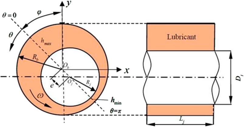
FIGURE 1. Nomenclature of journal bearings.
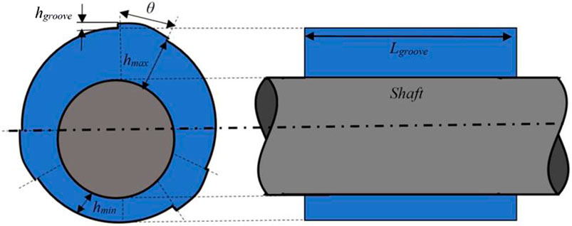
FIGURE 2. Nomenclature of multistep journal bearings.
Validation was conducted to perform simulations with the same geometry and boundary conditions as Zhang et al. (2014). Future studies should conduct validation with less than 10% error by changing the flow type and multistep additions to the geometry during variation.
The meshing process was conducted on fluid geometry. In the case of validation and variation, the geometry goes through a meshing process using the ANSYS mesh feature to obtain the expected quality. The mesh to be used comprises a uniform hexahedral grid formed using the face meshing feature. Figure 3 shows the meshing simulation results.
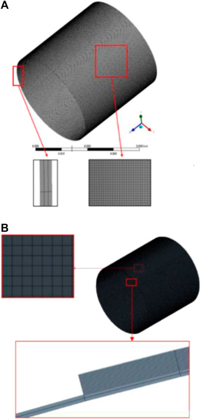
FIGURE 3. Meshing of (A) smooth journal bearing; (B) multistep journal bearing.
The boundary conditions were defined according to Zhang et al. (2014) data as a validation reference. Table 2 shows the definition of boundary conditions.

TABLE 2. Boundary conditions in simulation ANSYS.
The simulation employed a pressure-based solver and the SIMPLEC pressure–velocity coupling method to obtain the results quickly. The first-order upwind scheme was used for the momentum equations, volume fraction, and energy discretization. The convergence precision employed is 1.0 × 10⁻⁴ and 1.0 × 10⁻⁶ for the pressure and energy, respectively.
3 Results and discussion
This section discusses the calculation results from the case studies conducted. Each case used CFD) software in solving hydrodynamics (EHD) lubrication problems on journal bearings.
The hydrodynamic pressure and wall temperature distribution results were compared with the numerical data of Zhang’s simulation under the same input conditions. Operational parameters were then computed without considering deformation in the CFD model. Table 3 compares the contours of the reference study and this study.
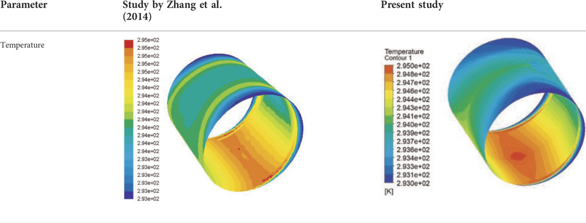
TABLE 3. Comparison contour of study reference and the present study.
This validation case could also be considered from the maximum and minimum temperatures achieved. The simulation results showed that the maximum and minimum temperatures are similar to Zhang’s. Table 4 shows the maximum temperature obtained from the simulation and its error comparison. It shows the maximum and minimum temperature values between the reference study and this study.
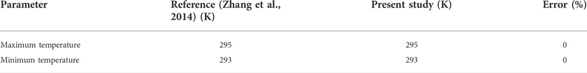
TABLE 4. Comparison between this study and study reference.
The previous explanation showed that the results obtained are valid because they have a minimal error difference between Zhang’s and the present study. A grid independence test was performed to confirm that these results are accurate with no errors in meshing. The simulation grid test was conducted by adding a face layer to the journal bearing. The meshing results are considered stable when the parameters are not affected by changes in the meshing elements. Figure 4 shows the grid test results.
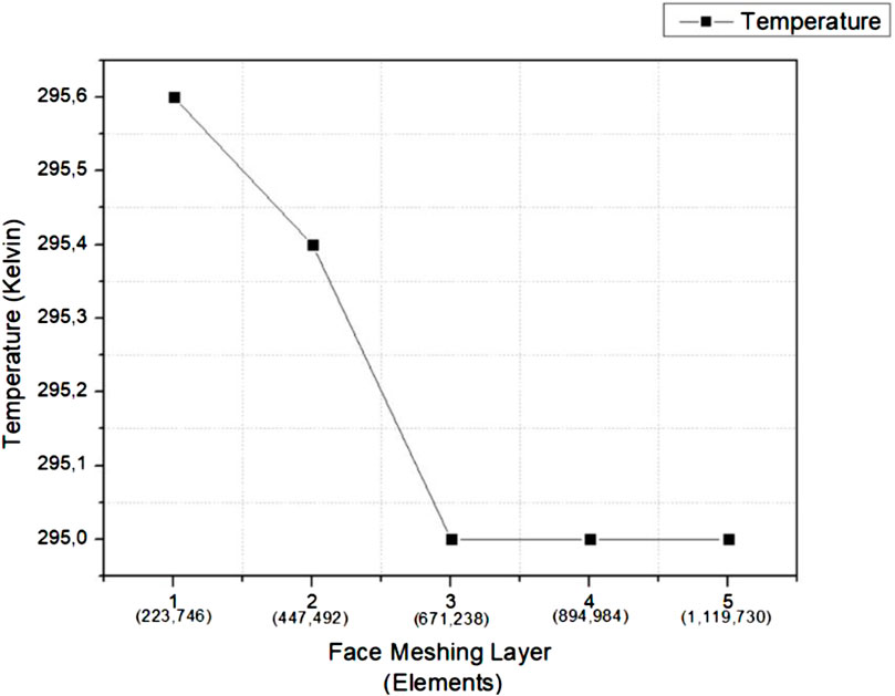
FIGURE 4. Grid independency test result.
Figure 4 shows the simulation grid test with an eccentricity ratio of 0.7 and an angular velocity of 3000 RPM. The simulation is stable when it has more than three layers. Furthermore, an independent test and a rechecking of the meshing were conducted on the skewness to double-check to ensure that the meshing results are of good quality. The meshing results on the three layers met the feasibility with a good maximum skewness of 0.49617.
The first variation showed the effect of turbulence modeling on smooth tribology journal bearing performance by considering several parameters, including pressure. Figure 5 shows the impact of turbulence modeling on pressure parameters.
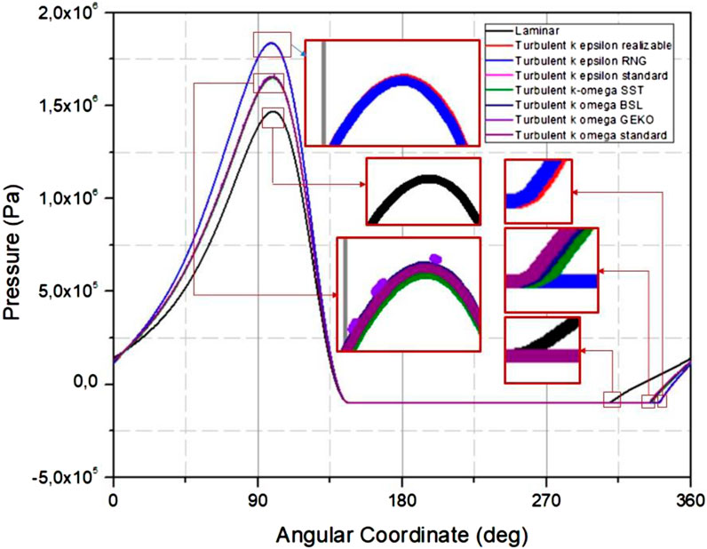
FIGURE 5. Plot of pressure at the midplane smooth journal bearing, ε = 0.7 dan ω = 3,000 rpm.
The pressure value by considering k-epsilon and k-omega is always above the laminar flow. Turbulent flow has a higher pressure value than laminar flow. From Figure 5, it can be seen that the most elevated pressure is 1.838 MPa, generated using the standard k-epsilon turbulent calculation model. The pressure trend was generated from the simulation by modeling the viscosity calculations of k-omega and k-epsilon. The k-omega viscosity calculation model produces a smaller pressure than the k-epsilon viscosity calculation model.
Turbulent viscosity modeling using k-epsilon and k-omega always produces more pressure than laminar viscosity modeling. As a result, turbulent flow always has more significant pressure than laminar flow. The maximum pressure generated by laminar and turbulent flows is 1.47 and 1.838 MPa, respectively. Figure 6 shows the pressure distribution contour of the simulation results. Based on Figure 6, it can be observed that the k-epsilon turbulence model gives a higher maximum pressure compared to the k-omega turbulence model.
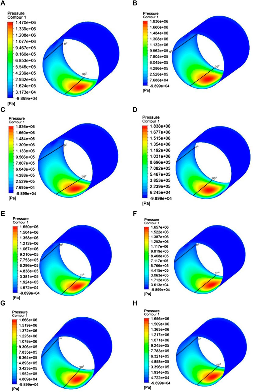
FIGURE 6. Contour of pressure from the smooth journal bearing dengan, ε = 0.7 dan ω = 3,000 rpm. (A) Laminar flow and turbulence flow with the viscosity model; (B) k-epsilon realizable; (C) k-epsilon RNG; (D) k-epsilon standard; (E) k-omega SST; (F) k-omega BSL; (G) k-omega GEKO; and (H) k-omega standard.
Turbulent performance could be viewed from the pressure in the lubricating fluid and the LCC. LCC is closely related to the resulting pressure because it results from the integral surface pressure. Figure 7 shows LCC generated from the simulation.
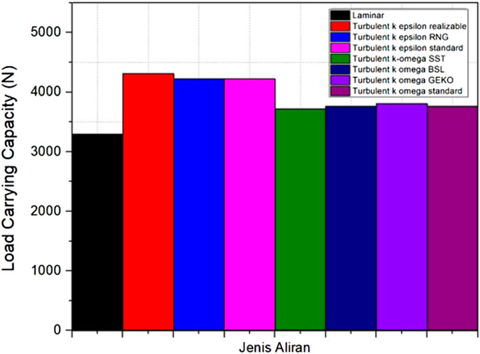
FIGURE 7. Smooth journal bearing dengan, ε = 0.7 dan ω = 3,000 rpm LCC.
Modeling by considering the effect of turbulence increases the LCC. The highest LCC was achieved in the simulation by considering the realizable k-epsilon as turbulence modeling with a value of 4321 N. When viewed from the LCC trend, k-epsilon turbulence modeling had a higher LCC value than k-omega turbulence modeling. Therefore, the simulation in case III only varies the difference between k-epsilon and k-omega regardless of modeling type.
The second variation stage showed the effect of turbulence on the journal bearing added as a multistep. Changes in geometry affect the results of tribology performance in lubrication cases. Therefore, it is necessary to simulate the effect of turbulence on multistep journal bearings. The simulation in the second variation stage uses bearing geometry as in validation but with a multistep. Figure 8 is the result of the pressure generated from the simulation of case III.
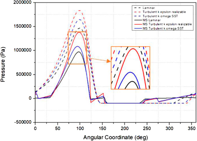
FIGURE 8. Plot of pressure at the midplane smooth journal bearing and multistep journal bearing, ε = 0.7 dan ω = 3,000 rpm.
The pressure distribution on the stationary midplane wall shows a similar multistep and smooth journal bearing trends. The highest pressure is achieved by turbulence modeling considering k-epsilon. The second highest and lowest pressures are achieved by turbulence modeling considering k-omega and laminar flow modeling, respectively. Figure 9 shows the multistep journal bearing pressure contour from this simulation. From Figure 9, it can be observed that the turbulence effect has a higher pressure peak compared with the laminar effect as shown in Figures 9B,C.
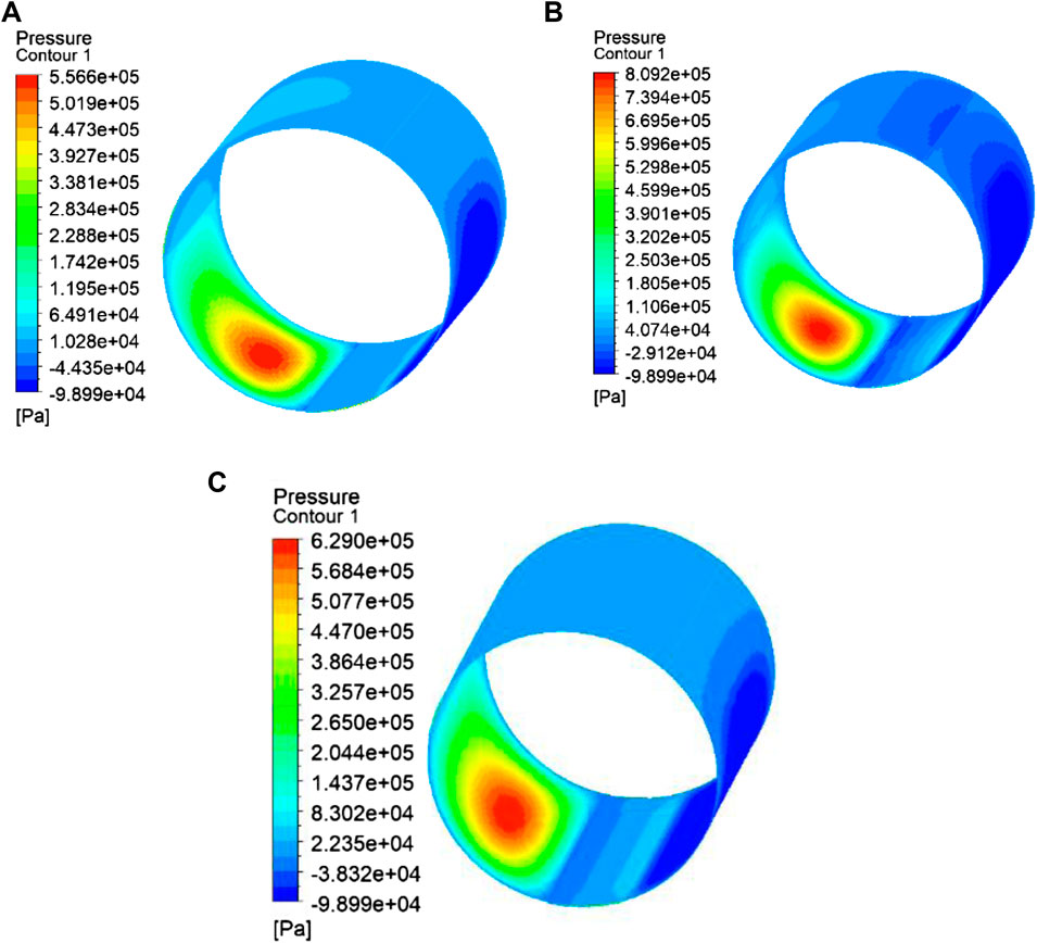
FIGURE 9. Pressure contour of the multistep journal bearing, ε = 0.7 dan ω = 3,000 rpm. (A) Laminar flow, (B) k-epsilon realizable, and (C) k-omega SST.
Tribological performance could be viewed from the pressure and the resulting cavitation area. Figure 10 shows the resulting cavitation graph.
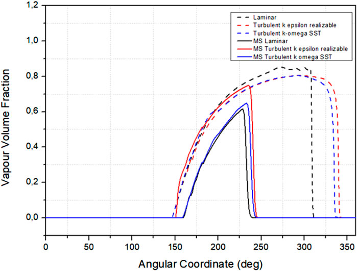
FIGURE 10. Plot of the vapor volume fraction at the midplane stationary wall multistep groove and smooth journal bearing, ε = 0.7 dan ω = 3,000 rpm.
The distribution plot shows that adding a multistep groove reduced the maximum vapor volume fraction in the journal bearing. This is indicated by a solid line with a lower maximum vapor volume fraction than the dotted line or a smooth journal bearing chart. Moreover, there is a decrease in the cavitation area with a multistep groove journal bearing. In laminar flow, multistep grooves and smooth journal bearings have vapor volume fractions at 160–240 and 146–312°, respectively. K-epsilon turbulent flow modeling and k-omega turbulent flow modeling have a total of 150–240° vapor volume fractions in multistep groove journal bearings. The vapor volume fraction appears at 135–335° in smooth journal bearings.
This decrease in the vapor volume fraction follows Yu Cen’s reference study, where adding a multistep groove journal bearing reduces the cavitation volume fraction. A decrease in pressure reduces the area where the vapor volume fraction occurs, lowering the cavitation frequency.
The volume fraction graph trend generated between multistep and smooth journal bearings is similar. Turbulence modeling by considering k-epsilon has the highest volume fraction value while laminar modeling has the lowest value.
4 Conclusion
This study analyzed the thermo-hydro-dynamic behavior of multistep journal bearings by investigating the hydrodynamic pressure, the volume fraction of vapor, the temperature, and the friction force. To explore phase changes, it used CFD approaches, including the multiphase “MIXTURE” cavitation model. In addition, the effects of shaft rotation speed and the potential benefits of using a step were discussed. The findings and discussion resulted in the following conclusion:
1) Flow modeling using turbulent flow modeling increases the pressure value more than laminar flow modeling on smooth journal bearing simulations.
2) Turbulence flow modeling using the k-epsilon model has higher temperature and pressure than the k-omega model.
3) Modeling the flow into turbulent flow increases the pressure and temperature than laminar flow against multistep journal bearings.
4) Adding a multistep reduces the resulting pressure and cavitation area.
Data availability statement
The original contributions presented in the study are included in the article/Supplementary Material; further inquiries can be directed to the corresponding author.
Author contributions
Conceptualization, MM and MT; methodology, JJ; software, BS; validation, MM, EY, and DW; formal analysis, MM; investigation, MT; resources, JJ; data curation, BS; writing—original draft preparation, MM and DW; writing—review and editing, MM and EY; visualization, MT and BS; supervision, JJ; project administration, MM; funding acquisition, JJ. All authors have read and agreed to the published version of the manuscript.
Conflict of interest
The authors declare that the research was conducted in the absence of any commercial or financial relationships that could be construed as a potential conflict of interest.
Publisher’s note
All claims expressed in this article are solely those of the authors and do not necessarily represent those of their affiliated organizations or those of the publisher, the editors, and the reviewers. Any product that may be evaluated in this article or claim that may be made by its manufacturer is not guaranteed or endorsed by the publisher.
References
Biswas, N., and Chakraborti, P. (2015). Transient analysis of 3-lobe bearings considering surface roughness effect for A gas turbine. 6th BSME Int. Conf. Therm. Eng. 105, 225–231. doi:10.1016/j.proeng.2015.05.098
Bompos, D. A., and Nikolakopoulos, P. G. (2016). Tribological design of a multistep journal bearing. Simul. Model. Pract. Theory 68, 18–32. doi:10.1016/j.simpat.2016.07.002
Chen, Y., Sun, Y., and Chunping, C. (2017). Investigations on influence of groove shapes for the journal bearing in high-speed and heavy-load press system. Industrial Lubr. Tribol. 70, 230–240. doi:10.1108/ILT-02-2016-0036
Cupillard, S., Glavatskih, S., and Cervantes, M. J. (2010). Inertia effects in textured hydrodynamic contacts. Proc. Institution Mech. Eng. Part J J. Eng. Tribol. 224 (8), 751–756. doi:10.1243/13506501JET697
Dhande, D. Y., and Pande, D. W. (2017). A two-way FSI analysis of multiphase flow in hydrodynamic journal bearing with cavitation. J. Braz. Soc. Mech. Sci. Eng. 39, 3399–3412. doi:10.1007/s40430-017-0750-8
Dousti, S., Cao, J. M., Younan, A., Allaire, P., and Diamond, T. (2012). Temporal and convective inertia effects in plain journal bearings with eccentricity, velocity, and acceleration. J. Tribol. 134, 31704. doi:10.1115/1.4006928
Kohnke, P. (1999). ANSYS theory reference - release 5. Available at: http://research.me.udel.edu/∼lwang/teaching/MEx81/ansys56manual.pdf. (Accessed Nov, 2013).6, 1286.
Li, Q., Zhang, S., Wang, Y., Xu, W. W., and Wang, Z. (2019). Investigations of the three-dimensional temperature field of journal bearings considering conjugate heat transfer and cavitation. Industrial Lubr. Tribol. 71, 109–118. doi:10.1108/ilt-03-2018-0113
Malcom, E., and Leader, P. (2001). Understanding journal bearings. Colorado: Applied Machinery Dynamics Co, 1–26.
Mereles, A., and Cavalca, K. L. (2021). Modeling of multi-stepped rotor-bearing systems by the continuous segment method. Appl. Math. Model. 96, 402–430. doi:10.1016/j.apm.2021.03.001
Susilowati, A., Tauviqirrahman, M., Jamari, J., Bayuseno, A. P., and Muchammad, M. (2016). A comparative study of finite journal bearing in laminar and turbulent regimes using CFD (Computational Fluid Dynamic). Matec Web Conf. 58, 04001. doi:10.1051/matecconf/20165804001
Tala-Ighil, N. (2008). Hydrodynamic effects of texture geometries on journal bearing surfaces. Fascicle VIII: The Annals of University “Dunărea De Jos“ Of Galati, 47–52. Tribology.
Venkateswarlu, N. J., Rao, E. V., Venugopal, S., and Akella, S. (1990). Three-dimensional laminar and turbulent lubrication in journal bearings. Wear 136 (2), 263–279. ISSN 0043-1648. doi:10.1016/0043-1648(90)90151-y
Wang, X. L., Adachi, K., Otsuka, K., and Kato, K. (2006). Optimization of the surface texture for silicon carbide sliding in water. Appl. Surf. Sci. 253 (3), 1282–1286. doi:10.1016/j.apsusc.2006.01.076
Zhang, W. (2022a). A novel ceramic with low friction and wear toward tribological applications: Boron carbide-silicon carbide. Adv. Colloid Interface Sci. 301, 102604. doi:10.1016/j.cis.2022.102604
Zhang, W. (2022b). Tribology of SiC ceramics under lubrication: Features, developments, and perspectives. Curr. Opin. Solid State Mater. Sci. 26 (4), 101000. doi:10.1016/j.cossms.2022.101000
Keywords: CFD, hydrodynamics lubrication, multistep journal bearing, turbulence, tribological performance
Citation: Muchammad M, Wibowo DDP, Tauviqirrahman M, Setiyana B, Yohana E and Jamari J (2022) Investigation of the influence of turbulence to tribological performance on smooth and multistep journal bearing with hydrodynamics simulation. Front. Mech. Eng 8:946074. doi: 10.3389/fmech.2022.946074
Received: 17 May 2022; Accepted: 08 August 2022;
Published: 06 September 2022.
Edited by:
T. V. V. L. N. Rao, Madanapalle Institute of Technology & Science, IndiaReviewed by:
Jinlong Liu, Zhejiang University, ChinaWei Zhang, Institute of Metal Research (CAS), China
Lin Zhong, Southwest Petroleum University, China
Copyright © 2022 Muchammad, Wibowo, Tauviqirrahman, Setiyana, Yohana and Jamari. This is an open-access article distributed under the terms of the Creative Commons Attribution License (CC BY). The use, distribution or reproduction in other forums is permitted, provided the original author(s) and the copyright owner(s) are credited and that the original publication in this journal is cited, in accordance with accepted academic practice. No use, distribution or reproduction is permitted which does not comply with these terms.
*Correspondence: M. Muchammad, bV9tYWQ1MzczQHlhaG9vLmNvbQ==