 Prashant Patunkar1*
 Sunil Dingare2
- 1Mechanical Engineering Department, MIT Art, Design and Technology University, Pune, India
- 2Aerospace Engineering Department, MIT Art, Design and Technology University, Pune, India
The satisfactory performance of indirect evaporative cooling techniques (IEC) is governed significantly by the structural and design arrangement of heat and mass exchange devices. The experimental performance of the dew point evaporative cooler has been investigated in the present work with the geometrically modified flow passages for air and water. Conventionally, these passages are formed by either flat or corrugated plates. The trapezoidal corrugated plate has been used to form these passages for air and water. The laboratory trials were conducted for the different combinations of intake air temperature, specific humidity, and air velocity. The performance in terms of dew point and wet bulb efficiency is presented based on laboratory trials. The experimental results achieved dew point and wet bulb efficiencies ranging between 52% and 82% and 74% and 126%, respectively. The geometrically modified flow passages increase the heat exchange area for the same volume of a similar heat exchange device and achieve an increased thermal performance of the proposed cooler.
Introduction
The gross energy requirements for the building sector account for nearly one-third of the global energy requirements and release of carbon emissions. Out of the total energy consumed in buildings, half of it is utilized for cooling purposes (Luis et al., 2008). The cooling of buildings has become an important feature in applications such as commercial offices, metro stations, shopping and sports complexes, and industrial units to name a few of them. The studies also reveal that indoor human thermal comfort is of high priority over visual and acoustic comfort (Frontczak and Wargocki, 2011). The cooling requirements for such applications are mainly dominated by mechanically driven vapor compression systems, which are highly energy consuming. The evaporative cooling method is now being considered an option over conventional vapor compression systems. This method consumes nearly 75% less power as compared to conventional vapor compression systems (Cerci, 2003). Such methods would make a significant contribution to reducing energy requirements and harmful emissions to the environment. Evaporative cooling has been used since ancient times employing water-filled earthen pots to cool the air. Such arrangements were widely used to cool historic buildings and monuments, and they quickly gained popularity in many regions around the world, particularly in hot and arid climates (Committee on climate change, 2008).
Direct evaporative cooling (DEC) and indirect evaporative cooling (IDEC) are the two methods of evaporative cooling (EC). DEC deals with the physical mixing of ambient air with water and causes the gain of air moisture. The increased moisture in the air may add discomfort to the occupants and leads to hygiene problems additionally. The performance in terms of efficiency is typically in the range of 70–95% in the relevance of temperature drop. IEC uses a heat exchanger which employs diversified air and water flow passages. In this arrangement, the air is cooled sensibly. IEC achieves efficiency ranging between 40 and 60%, substantially lower than DEC (Maheshwari et al., 2001).
The issues associated with DEC and IEC have been investigated by numerous researchers recently. The recent works on dew point evaporative coolers have aided in obtaining conditioned air temperatures that are less than the ambient air’s wet bulb temperature (WBT) and near the dew point temperature (DPT). The increased human thermal comfort justifies the widespread applications of such systems over DEC systems. The drawbacks of traditional evaporative cooling systems have been addressed by numerous researchers through modifications in the geometry of heat exchanger plates and their diverse arrangements, such as cross flow, counter flow, and cross-counter flow.
The novel arrangement for air cooling operated by the ‘Maisotsenko cycle (M-cycle)’ (Maisotsenko et al., 2003) has been proposed to obtain air temperature lower than WBT and approaching the DPT. The layout of such arrangement for counter-flow configuration for modified fluid flow passages is shown in Figure 1.
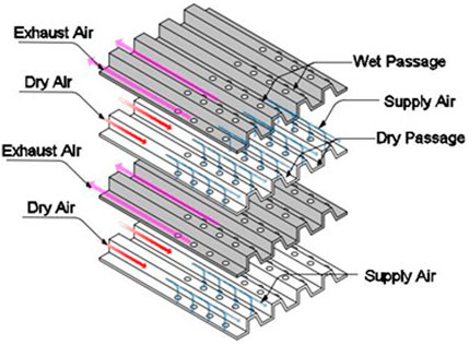
FIGURE 1. Layout of the counter-flow configuration.
A heat exchanger is made of alternate wet and dry passages. The product air and working air are made to circulate in dry passages. The fraction of working air is recirculated via wet passages and perforated holes. The energy transfer occurs between product and precooled working air due to the phase change of water and is directed towards the exhaust to the ambient. The product air is also cooled simultaneously along dry passages on account of heat transfer to the adjacent wet passages. This phenomenon achieves a product air temperature lower than WBT accompanied by constant specific humidity.
Extensive experimental research has been conducted to validate the models proposed for numerical studies covering numerous intake air conditions. Riangvilaikul and Kumar (2011) tested the effect of a counter-flow cooler in different climates. Wet bulb efficiency (WBE) and dew point efficiency (DPE) were found to be in the range of 0.92–1.14 and 0.58–0.84, respectively. Frank Bruno (2011) conducted on-site experimental testing of a counter-flow cooler for residential and commercial applications. The experimental results obtained WBE in the range of 0.93–1.06 and 1.18–1.29 for commercial and residential applications, respectively. Lee et al. (2013) compared the experimental thermal performance of flat plate, corrugated plate, and finned channel arrangements. He further proposed that the finned channel arrangement was compact among three arrangements and achieves WBE close to 1.2 under the testing conditions. Jradi and Riffat (2014) numerically and experimentally investigated the performance of the cross-flow cooler and achieved WBE and DPE as 1.12 and 0.78 respectively. Further, the cooler performance was optimized by parametric studies. Lv et al. (2021) proposed a fibrous membrane-coated dew point cooler over the wet channels to achieve better permeability and diffusion feature. The experimental studies showed WBE and DPE in the range of 0.42–0.8 and 0.28–0.61, respectively, and further stated that, air humidity significantly affected WBE and DPE over other parameters. Abadi et al. (2020) proposed a numerical model and validated experimentally the thermal performance of finned channel cooler to study the effect of the number of channels for different configurations of heat and mass exchanger. Jia et al. (2019) experimentally investigated and compared cross-flow cooler with Polystyrene–Nylon (PN) fiber and Aluminum foil (ALF) coating over wet surface for performance improvement. The investigations proposed enhanced performance of PN coated cooler over ALF coated cooler under testing conditions. Liu et al. (2019) investigated the performance experimentally and numerically of corrugated and flat plate dew point coolers. Experimental tests obtained WBE and DPE as 1.14 and 0.68, respectively. The numerical simulation revealed more than 10% better performance for corrugated plate coolers than flat plate coolers. Pakari and Ghani (2019) proposed a 1D and 3D numerical model and verified the efficacy of a counter-flow dew point cooler experimentally. The proposed cooler attained a WBE of 1.25 in an experiment. Xu et al. (2017) studied the performance of a dew point cooler with a high-performance wet layer material, an innovative heat exchange device, and a pulsating water circulation system in an experimental setting. The proposed cooler attained the WBE and DPE of 1.14 and 0.75, respectively, for test conditions of 37.8°C dry bulb temperature and 21.1°C wet bulb temperature.
The previous research studies carried out were mainly based on the cooler with cross-flow configuration heat exchangers. The benefit of quick adaptability from the commercial air-to-air heat exchanger to the regenerative arrangement is the major cause of this fact. The large size of the cross-flow configuration is a major limitation as compared to regenerative configurations. Zhao et al. (2008) proposed a numerical study of counter-flow configuration and studies revealed that cooler performance depends significantly on the sizing of air flow passages, velocity, and extraction ratio and least dependent on evaporating water temperature and further possible multi-response optimization also reviewed for the selection of the corrugated configurations (Pagar and Gawande, 2020). A.M.E.Abadi et al. (2020) investigated numerically and experimentally for the first time the effect of the number of channels on the performance of counter-flow M-Cycle based IEC for five arrangements with different channel numbers. The experimental and model results showed good agreement. F.Comino et al. (Comino et al., 2022) developed a model based on the ε-NTU technique for the operation of an IEC unit subjected to conditions aligned with European ventilation rules. The low airflow rates achieved peak COPs of 50.26, 44.19, and 37.14 for an office, restaurant, and auditorium respectively. The performance of IEC, being a passive cooling system, is impacted by the moisture content in the air and possesses limited scope of temperature and humidity regulation. This issue has been experimentally addressed by Q. Chen et al. (2021) with the help of a joint IEC and mechanically operated system (MOS) with the cross-flow arrangement. The sequence involved initial precooling of incoming air followed by treating it as per the required conditions with the help of MOS. The integrated system obtained an incoming air temperature drop of 6–15°C and specific humidity of 0.5–4 g/kg of dry air, respectively. Q. Chen et al. (2022) conducted a similar experimental study for an integrated system and recommended a pragmatic model for speedy investigation of the phenomenon. M. Ali et al. (2021) studied experimentally the IEC with structurally redesigned dry passages in order to achieve enhanced performance. The structurally redesigned arrangement showed improvements of 25% for temperature drop, 18% for cooling power, and a peak of 37% for WBE and DPE at the expense of increased pressure drop. W. Shi et al. (2022) experimentally investigated the cross-flow plate IEC impregnated with an absorptive coat over the secondary air channel surface. The test results revealed a prolonged cooling effect without water spray due to the excellent characteristics of the absorptive coat. The reduced pressured drop and enhanced COP proved to be advantageous for the intermittent operation of a water pump. The experimental study has been conducted by R. Kausar et al. (2022) to investigate the effect of operational conditions for analyzing the 4E, i.e., energy, exergy, economic, and environmental aspects for counter- and cross-flow arrangements of the M-Cycle-based DPEC unit.
The literature review conducted focuses on the different heat exchanger configurations, geometry of the heat exchanger plates, effects on incoming air parameters, channel sizing, etc. No studies have so far been done to assess the experimental performance of the coolers with modified air and water passageways. The present research focuses on the study of an experimental performance cooler with a counter-flow heat exchanger constructed of trapezoidal corrugated plates. The trapezoidal corrugated plate forms the modified flow passages for air and water in the cooler. The demonstration model has been experimentally investigated in the HVAC Laboratory of MIT Art, Design and Technology University, Pune, India, for different incoming air conditions. The experimental results obtained for trapezoidal corrugated plate flow passages of air and water are compared with experimental results of flat and corrugated plates. The impact of intake air temperature and velocity at constant specific humidity on the supply air temperature, WBE, and DPE are discussed in the present work.
Experimental apparatus for performance testing, performance parameter, and testing method
Experimental apparatus
The WBE and DPE of the proposed cooler arrangement are experimentally investigated by modifying the air and water flow passages from corrugated plates to trapezoidal corrugated plates, which provides a larger heat transfer area. The changes in the passage geometry form a major parameter for the construction and design of a counter-flow dew point evaporative cooler. The heat exchanger plates are made of aluminum, thus enabling them to be lightweight. Figure 2 shows the layout for the proposed cooler to be experimentally investigated, and the fabricated setup of the cooler is shown in Figure 3.
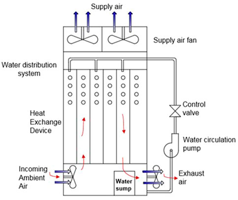
FIGURE 2. Layout for the proposed cooler.
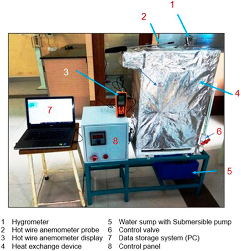
FIGURE 3. Fabricated test setup of the proposed cooler.
The proposed cooler consists of alternate sheets, thus forming the arrangement for dry and wet passages for air and water separately. The multiple sheets are tied together mechanically, and either side of the wet passages is made waterproof to limit the diffusion of water from the wet to the dry side. The high capability water retaining cotton is placed on the wet side to obtain a uniform wetting surface. The perforations in the form of small holes are provided over the sheets along the flow direction of air so as to recirculate part of the air through the wet passages. Such flow arrangement provides a regenerative type of cooling for the incoming air to achieve large temperature drops. The circulation of water from the sump placed at the bottom of the arrangement is carried out with help of a submersible pump. The control valve is provided to regulate the flow rate of the water as per the requirements. The water is sprayed from the top of the arrangement with the help of a flexible tube and holes provided around its periphery to ensure the uniform spraying of the water, and it completely wets the water-retaining cotton. The intake and exhaust fans are used to ensure the proper airflow in the experimental setup. The flow rates of the air are modulated with the fan operating speed.
The dew point evaporative cooling arrangement provided with trapezoidal corrugated sheets are having the dimensions of 640 mm length, 400 mm width, and 200 mm depth with counter-flow heat exchanger configuration and tested for different operating and inlet air conditions. The heat exchanger consists of alternate modified dry and wet flow passages. The spacing between the dry and wet flow passages is maintained uniformly as 5 mm. The geometric details of flat, corrugated, and trapezoidal corrugated plates for air and water flow passages are shown in Figures 4A–C, respectively. The dimensions of the dry and wet passages for all the plates of the cooler are illustrated in Table 1.
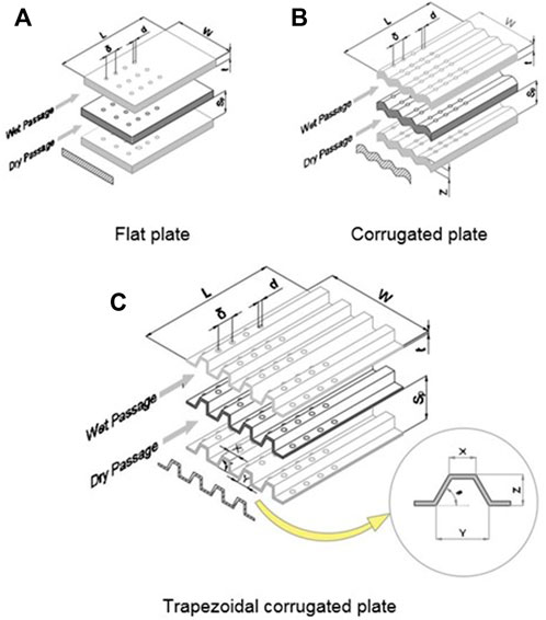
FIGURE 4. Geometries of air and water flow passages for the (A) flat plate, (B) corrugated plate, and (C) trapezoidal corrugated plate.
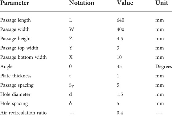
TABLE 1. Dimensions of the dry and wet passages for all plate geometries.
The arrangement for modified air and water flow passages of the trapezoidal corrugated plate configuration is shown in Figure 5.
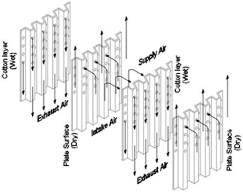
FIGURE 5. Modified fluid flow passages for the trapezoidal corrugated plate.
Performance parameters
The evaluation of performance parameters for the proposed cooler was carried out by the measurement of the intake and supply air temperatures and specific humidity. The performance study of the cooling system is measured by WBE and DPE, respectively, and depends mainly on the inlet and outlet air conditions. Both performance parameters are defined in (Lee et al., 2013) and expressed as follows:
where
Experimental testing methodology
The fabricated prototype of the cooler has been experimentally tested for altered inlet air settings of temperature, flow rate, and humidity. The feed air and discharge air flow rates at the intake of the dry channel and the exit of the wet channel were controlled by regulating the fan speed. The inlet and exhaust air temperature were measured with platinum resistance thermometers having an accuracy of ±0.1°C. The water circulation flow rate was determined by collecting the water in a graduated scale tank and recording the time with a stopwatch. The inlet and exhaust air relative humidity was recorded by humidity sensor (testo 610, accuracy ±0.5°C, ± 2.5% RH). The power required for the operation of fans and water circulation pump was measured by power meters with an accuracy of ±1%. The velocity of the incoming and exhaust air was measured by a hot wire anemometer (Generic, 0–30 m/s, accuracy ±3%).
Experimental results and discussion
The laboratory experiments have been conducted for different operating conditions and are mentioned in Table 2. The maximum relative uncertainty for supply air temperature was obtained as ±6%. The experimental results obtained for the flat, corrugated, and trapezoidal corrugated plate configurations are presented in the following.
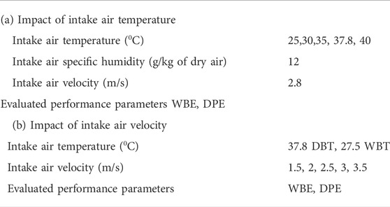
TABLE 2. Operating conditions for laboratory experiment.
Inlet air temperature influence on supply air temperature
The human comfort requirements are governed by the supply air temperature obtained at the end of dry passages of the heat exchanger. The WBE and DPE depend on the intake and supply air temperatures, as expressed in Eqs 1 and 2, respectively. Figure 6 depicts the influence of inlet air temperature on supply air temperature for various plate layouts.
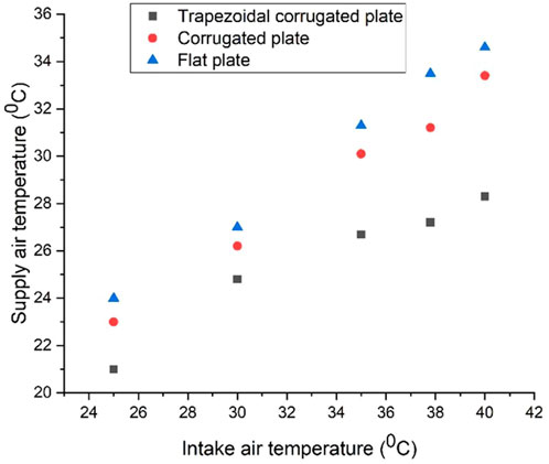
FIGURE 6. Changes in supply air temperature with intake air temperature.
For all plate arrangements, the supply air temperature drops as the intake air temperature drops. The fluctuation of supply air temperature as compared to intake air temperature is observed to be linear. A less temperature drop at a particular intake air temperature is observed for the corrugated and flat plate as compared to that of the trapezoidal corrugated plate. The higher supply air temperatures at higher intake air temperatures are attributed to the humid conditions of the incoming air. The supply air temperature difference at a particular incoming air temperature remains almost constant for flat and corrugated plates, respectively, whereas for the trapezoidal corrugated plates large temperature difference of supply air is obtained at a particular intake air temperature. Additionally, the supply air temperature difference narrows down between the trapezoidal corrugated plate and the other two plates, respectively. The experimental studies further revealed supply air temperature lower than 26°C would be achieved for trapezoidal corrugated plate configuration for the incoming air specific humidity of 12 g/kg of dry air.
Inlet air temperature influence on wet bulb efficiency
Figure 7 depicts the variations in wet bulb efficiency as a function of intake air temperatures for all plate heat exchanger layouts. With the known values of the intake and supply air temperatures, the WBE is calculated by Eq. 1. The WBE varies between 78% and 126% for the plate configurations, with the known intake air temperatures considered for the laboratory experiments.
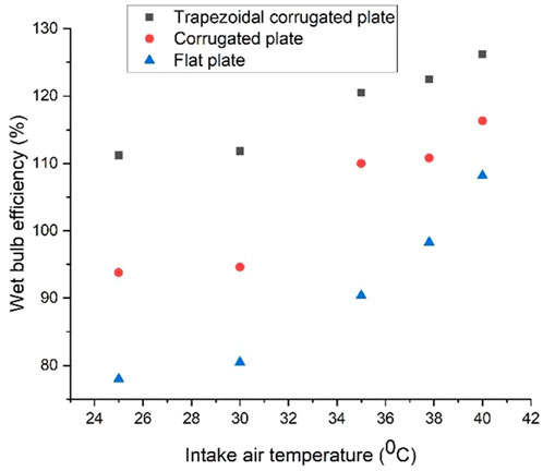
FIGURE 7. Changes in WBE with intake air temperature.
At lower incoming air-specific humidities, large values of WBE were achieved due to the greater potential of moisture to get diffused into the air. The laboratory experiments conducted indicate that for the higher intake air temperatures, the larger values are obtained for WBE. This phenomenon can be justified in the context that, enhanced temperature drops are obtained for higher intake air temperatures. The cooler arrangement with trapezoidal corrugated plates achieves superior WBE over flat and corrugated plates, respectively.
Inlet air temperature influence on dew point efficiency
Figure 8 depicts the variations in wet bulb efficiency as a function of intake air temperature for all plate heat exchanger layouts. The DPE is determined using Eq. 2 and known intake and supply air temperatures.
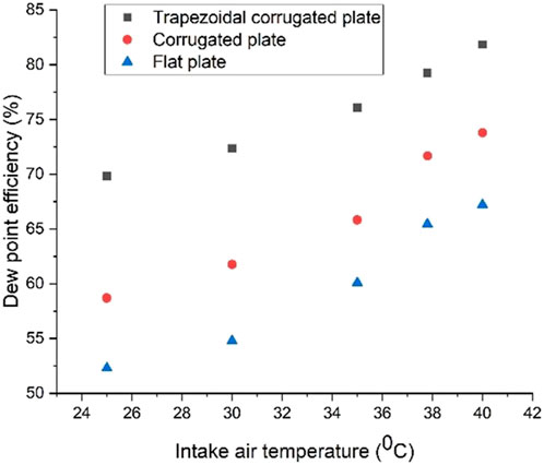
FIGURE 8. Changes in DPE with intake air temperature.
From Figure 8, it can be observed that the DPE varies linearly with the intake air temperatures. For the varying inlet air temperatures in the experiment, the DPE ranges between 52% and 82%. The DPE increases with the increased intake air temperature for all the plate configurations of the heat exchanger. The increase in DPE between the trapezoidal corrugated plate and the corrugated plate is more than the increase of DPE than that between the corrugated and flat plate. The difference between DPE for flat and corrugated plates remains almost constant for all incoming air temperatures. While this difference goes on increasing for the trapezoidal corrugated and corrugated plates as the incoming air temperature decreases.
Inlet air velocity influence on supply air temperature
The variation of supply air temperature at altered intake air velocities at a constant intake air temperature of 37.8°C DBT and 27.8°C WBT is shown in Figure 9. The supply air temperature rises as the intake air velocity rises. For all plate configurations, the supply air temperature is less than the intake air WBT when the intake air velocity is less than 2.5 m/s. The supply air temperature for only the trapezoidal corrugated plate is smaller than intake air WBT when the intake air velocity is 2.5 m/s. Hence, the usage of flat and corrugated plates is less effective when the intake air velocity is more than 2.5 m/s. The difference in supply air temperatures for all the plate configurations at a particular velocity varies in the range of 1°C–2.5°C.
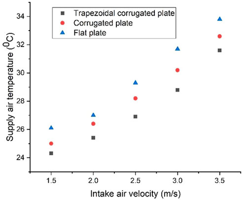
FIGURE 9. Changes in supply air temperature with intake air velocity.
Inlet air velocity influence on wet bulb efficiency
Figure 10 depicts the variance of WBE for various air inlet velocities.
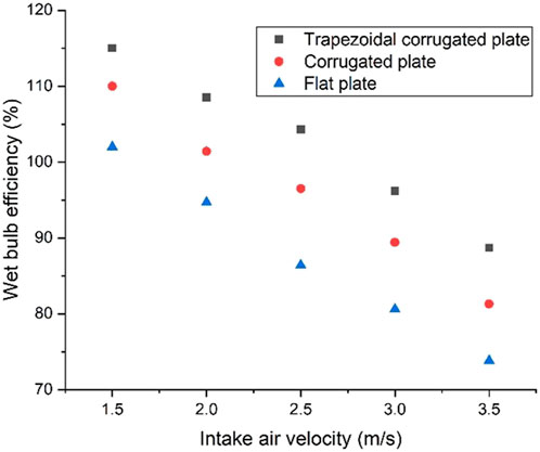
FIGURE 10. Changes in WBE with intake air velocity.
The WBE is inversely proportional to the intake air velocity. Only trapezoidal corrugated plate configuration has a WBE greater than 100% for a 2.5 m/s intake air velocity, whereas corrugated and flat plate configurations have a WBE less than 100%. When the intake air velocity is 1.5 m/s, the WBEs for all plate designs are larger than 100%. The WBE decreases with the increase in intake air velocity for all the plate designs, which is attributed to less effective cooling of the intake air.
Inlet air velocity influence on dew point efficiency
The variation of DPE for different intake air velocities is shown in Figure 11. The trends in the variation of DPE are observed similar to that of the trend of WBE for all the plate configurations. A substantial increase in the DPE is observed for the trapezoidal corrugated plate when compared with corrugated and flat plate configurations for the same intake air conditions. Thus, the trapezoidal corrugated plate configuration outperforms the other two plate configurations.
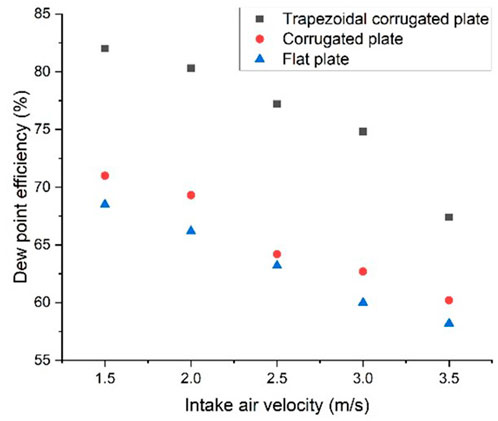
FIGURE 11. Changes in DPE with intake air velocity.
Comparison of WBE for the present and previous studies
The comparative variance of WBE and intake air temperature of the present work is shown in Figure 12. The WBE of the present study is compared with the numerical results of the previous studies for corrugated plates conducted by Liu et al. (2019) for the constant intake air velocity of 2 m/s.
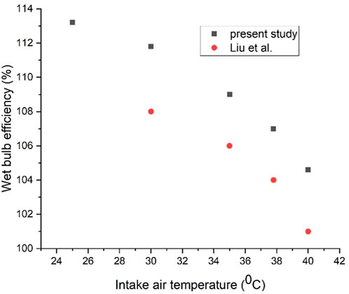
FIGURE 12. Comparison for variations in WBE with intake air temperature.
The WBE of the proposed cooler with trapezoidal corrugated plates is 3% higher than that of the corrugated plates from the previous studies. The difference in WBE remains almost constant with intake air temperature for both studies.
The trapezoidal corrugated plates show superior performance over corrugated plates, which is attributed to the increased cooler area for heat and mass exchange. The modification of the plate geometry from the corrugated to the trapezoidal corrugated configuration is the rational option for the performance enhancement of the cooler.
Conclusion
The experimental performance of the proposed cooler with a heat exchanger of trapezoidal corrugated, corrugated, and flat plate configurations has been studied in this work. The cooler with trapezoidal corrugated plate heat exchanger configuration provided enhanced performance over the corrugated and flat plate configurations. The experimental results achieved DPE ranging between 52% and 82%. Similarly, the WBE ranged between 74% and 126%. For the trapezoidal corrugated plate configuration, a WBE greater than 100% was obtained for the intake air velocity of 2.8 m/s. The operating parameters can further be optimized depending upon the specific need of the controlled environment for human thermal comfort.
Data availability statement
The original contributions presented in the study are included in the article/supplementary material; further inquiries can be directed to the corresponding author.
Author contributions
PP contributed to the design, fabrication, assembly, and subsequent laboratory trials on the prototype, preparation of the manuscript, and figures. SD provided valuable inputs during the design stage and necessary corrections in the final manuscript draft.
Conflict of interest
The authors declare that the research was conducted in the absence of any commercial or financial relationships that could be construed as a potential conflict of interest.
Publisher’s note
All claims expressed in this article are solely those of the authors and do not necessarily represent those of their affiliated organizations, or those of the publisher, the editors, and the reviewers. Any product that may be evaluated in this article, or claim that may be made by its manufacturer, is not guaranteed or endorsed by the publisher.
References
Abadi, A. M. E., Sadi, M., Gord, M. F., Ahmadi, M. H., Kumar, R., and Chau, K. W. (2020). A numerical and experimental study on the energy efficiency of a regenerative Heat and Mass Exchanger utilizing the counter-flow Maisotsenko cycle. Eng. Appl. Comput. Fluid Mech. 14 (14-1), 1–12. doi:10.1080/19942060.2019.1617193
Ali, M., Ahmad, W., Sheikh, N. A., Ali, H., Kousar, R., and Rashid, T. (2021). Performance enhancement of a cross flow dew point indirect evaporative cooler with circular finned channel geometry. J. Build. Eng. 35, 101980. doi:10.1016/j.jobe.2020.101980
Bruno, Frank (2011). On-site experimental testing of a novel dew point evaporative cooler. Energy Build. 43, 3475–3483. doi:10.1016/j.enbuild.2011.09.013
Cerci, Y. (2003). A new ideal evaporative freezing cycle. Int. J. Heat Mass Transf. 46, 2967–2974. doi:10.1016/s0017-9310(03)00072-3
Chen, Q., Ja, M. K., Burhan, M., Akhtar, F. H., Shahzad, M. W., Ybyraiymkul, D., et al. (2021). A hybrid indirect evaporative cooling-mechanical vapor compression process for energy-efficient air conditioning. Energy Convers. Manag. 248, 114798. doi:10.1016/j.enconman.2021.114798
Chen, Q., Ja, M. K., Burhan, M., Shahzad, M. W., Ybyraiymkul, D., Zheng, H., et al. (2022). Experimental study of a sustainable cooling process hybridizing indirect evaporative cooling and mechanical vapor compression. Energy Rep. 8, 7945–7956. doi:10.1016/j.egyr.2022.06.019
Comino, F., Romero-Lara, M. J., and de Adana, M. R. (2022). Experimental and numerical study of dew-point indirect evaporative coolers to optimize performance and design. Int. J. Refrig. 142, 92–102. doi:10.1016/j.ijrefrig.2022.06.006
Committee on Climate Change (2008). Building a low-carbon economy- the UK’s contribution to tackling climate change. London, UK: The Stationery Office, 210–250.
Frontczak, M., and Wargocki, P. (2011). Literature survey on how different factors influence human comfort in indoor environments. Build. Environ. 46, 922–937. doi:10.1016/j.buildenv.2010.10.021
Jia, L., Liu, J., Wang, C., Cao, X., and Zhang, Z. (2019). Study of the thermal performance of a novel dew point evaporative cooler. Appl. Therm. Eng. 160, 114069. doi:10.1016/j.applthermaleng.2019.114069
Jradi, M., and Riffat, S. (2014). Experimental and numerical investigation of a dew-point cooling system for thermal comfort in buildings. Appl. Energy 132, 524–535. doi:10.1016/j.apenergy.2014.07.040
Kousar, R., Ali, M., Amjad, M. K., and Ahmad, W. (2022). Energy, Exergy, Economic, Environmental (4Es) comparative performance evaluation of dewpoint evaporative cooler configurations. J. Build. Eng. 45, 103466. doi:10.1016/j.jobe.2021.103466
Lee, J., Chio, B., and Lee, D. Y. (2013). Comparison of configurations for a compact regenerative evaporative cooler. Int. J. Heat Mass Transf. 65, 192–198. doi:10.1016/j.ijheatmasstransfer.2013.05.068
Liu, Y., Akhlaghi, Y. G., Zhao, X., and Li, J. (2019). Experimental and numerical investigation of a high-efficiency dew-point evaporative cooler. Energy Build. 197, 120–130. doi:10.1016/j.enbuild.2019.05.038
Luis, P. L., Jose, O., and Christine, P. (2008). A review on buildings energy consumption information. Energy Build. 40 (3), 394–398. doi:10.1016/j.enbuild.2007.03.007
Lv, J., Xu, H., Xu, T., Liu, H., and Qin, J. (2021). Study on the performance of a unit dew-point evaporative cooler with fibrous membrane and its application in typical regions. case Stud. Therm. Eng. 24, 100881. doi:10.1016/j.csite.2021.100881
Maheshwari, G. P., Al-Ragom, F., and Suri, R. K. (2001). Energy saving potential of an indirect evaporative cooler. Appl. Energy 69, 69–76. doi:10.1016/s0306-2619(00)00066-0
Maisotsenko, V., Gillan, L. E., Heaton, T. L., and Gillan, A. D. (2003). Method and plate apparatus for dew point evaporative cooler. U. S. Pat. 6, 508402.
Pagar, N. D., and Gawande, S. H. (2020). Parametric design analysis of meridional deflection stresses in metal expansion bellows using gray relational grade. J. Braz. Soc. Mech. Sci. Eng. 42, 256. doi:10.1007/s40430-020-02327-0
Pakari, A., and Ghani, S. (2019). Comparison of 1D and 3D heat and mass transfer models of a counter flow dew point evaporative cooling system: Numerical and experimental study. Int. J. Refrig. 99, 114–125. doi:10.1016/j.ijrefrig.2019.01.013
Riangvilaikul, B., and Kumar, S. (2011). An experimental study of a novel dew point evaporative cooling system. Energy Build. 42, 637–644. doi:10.1016/j.enbuild.2009.10.034
Shi, W., Min, Y., Ma, X., Chen, Y., and Yang, H. (2022). Performance evaluation of a novel plate-type porous indirect evaporative cooling system: An experimental study. J. Build. Eng. 48, 103898. doi:10.1016/j.jobe.2021.103898
Xu, P., Ma, X., Zhao, X., and Fancey, K. (2017). Experimental investigation of a super performance dew point air cooler. Appl. Energy 203, 761–777. doi:10.1016/j.apenergy.2017.06.095
Keywords: flow passages, thermal comfort, counter current, efficiency, specific humidity, dew point
Citation: Patunkar P and Dingare S (2022) Study of the experimental performance of dew point evaporative cooling arrangement for modified fluid flow passages. Front. Mech. Eng 8:957898. doi: 10.3389/fmech.2022.957898
Received: 31 May 2022; Accepted: 29 September 2022;
Published: 11 November 2022.
Edited by:
Rajesh Baby, St.Joseph’s College of Engineering and Technology, Palai, IndiaReviewed by:
Xin Cui, Xi’an Jiaotong University, ChinaPatrick Jacob Shamberger, Texas A and M University, United States
Copyright © 2022 Patunkar and Dingare. This is an open-access article distributed under the terms of the Creative Commons Attribution License (CC BY). The use, distribution or reproduction in other forums is permitted, provided the original author(s) and the copyright owner(s) are credited and that the original publication in this journal is cited, in accordance with accepted academic practice. No use, distribution or reproduction is permitted which does not comply with these terms.
*Correspondence: Prashant Patunkar, cHJhc2hhbnQucGF0dW5rYXJAbWl0dW5pdmVyc2l0eS5lZHUuaW4=