 Garima Nema
 K Karunamurthy
- School of Mechanical Engineering, Vellore Institute of Technology, Chennai, India
Solar desalination has captivated consideration to overcome the problem of the scarcity of freshwater, with simple-design, economic, and environment-friendly solutions. This study navigates a novel solar-evacuated glass tube collector integrated with a collective condenser heat pipe system for solar desalination. A newly designed heat pipe array was represented in this work by affixing all the evaporator tube units of the heat pipes to a single condenser unit and was attached to the evacuated tube solar collector. The innovative assembly of the heat pipe provided uniform heating of water and rapid steam generation. The present system acts as a solar collector and as a stand-alone basin for freshwater formation. The performance assessment of the neoteric system was conducted based on half-filled and three-fourth-filled conditions of the water flow pipe kept within the collective condenser heat pipe. The maximum heat pipe temperature recorded during the half-filled state was 156.9°C and 151.48°C in the three-fourth-filled state. The half-filled state of the water flow pipe delivered a total distilled water content of 8,050 ml/day, whereas the three-fourth-filled state delivered 5,925 ml/day of distilled water. The maximum energy and exergy efficiency of the presented system was 19.27% and 3.92%, respectively. The economic minimum unit cost of freshwater by the present system is 4.27 INR, and the payback period is 2.9 years. The present eco-friendly energy system saves 4.25 kWh of electricity and 4.16 × 10⁻³ tons of CO2 equivalent per year.
1 Introduction
Water is nature’s gift for living beings and plays a vital role in the development of an economy and the welfare of a nation. Nearly 70% of Earth’s surface is covered with water, out of which 97% is oceanic, approximately 2% is stored as ice in the polar region, and only 1% is fresh water available for the needs of the plants, animals, and human beings (Kumar and Bai, 2008). Drinking water demand has been increasing by 1% per year worldwide, driven by a combination of population growth, industrial growth, socio-economic development, changing consumption patterns, and water pollution in natural freshwater reservoirs (Chakraborti et al., 2019; Chen et al., 2020; Nema and Karunamurthy, 2021).
Desalination of sea and brackish water provides a solution to this scarcity problem of portable water (Garcia-Rodriguez, 2007; Kaushal and Varun, 2010; Sathyamurthy et al., 2016; Nagarajan et al., 2017; Yu et al., 2018). However, for using these techniques, a huge amount of energy is required, which is now obtained from hydrocarbon deposits. Its limitations like limited available quantity, expensive, as well as its uses lead to environmental degradation. So, solar energy, which is a renewable energy source, is the best possible solution for water desalination.
Among desalination technologies, a solar still is the simplest and most economical device with low maintenance requirements but has limited productivity. To enhance solar still productivity, it was coupled with different types of stills, collectors, heat storage devices, nanofluids, hot air injection, etc. The active mode of the solar still improves the heat transfer coefficient and increases the conductivity of fluid. Preheating enhances brackish water temperature, cover-plate cooling enhances the freshwater condensation rate, and the phase change material absorbs energy at day time and liberates heat in the absence of sunshine due to which evaporation occurs in the absence of sunlight. The use of nanofluids increases the conductivity of the fluid by adding small particles of solids (Voropoulos et al., 2001; Badran et al., 2005; Abdel-Rehim and Lasheen, 2007; Tabrizi et al., 2010; Arunkumar et al., 2016; Kabeel et al., 2016; Singh et al., 2016; Kabeel and Abdelgaied, 2017).
Solar collectors for solar devices are the most attractive solution, which enhances productivity. Two types of collectors are used for preheating fluid, namely, flat plates and evacuated tube solar collectors (Sokhansefat et al., 2018). Due to their simple design, great dependability, and low maintenance, FPSCs are the most often used solar collectors for water heating applications. But, energy markets are dominated by ETSCs due to high thermal efficiency, high fluid outlet temperature, and low initial cost (Chopra et al., 2018).
Yadav integrated a flat plate collector with a solar still to compare the efficiencies, with and without a pump by numerical calculations through thermal analytical energy modeling. A flat plate collector is used for single-slope solar still water heating, and this water was circulated through a pump. The result indicates that the yield was enhanced by 30–35% in forced circulation (Yadav, 1991). Negi et al. conducted an experimental analysis of a tilted wick single slope and basin solar still coupled with a flat plate collector. The findings from the experiment show that the efficiency of the horizontal wick type still becomes 16.6% higher than that of the conventional still. The overall cumulative efficiency of the tilted wick basin at 30° with a flat plate collector was achieved at 22.1%. They also found that a tilted wick basin at 30° gives maximum yield compared to the conventional still (Negi et al., 2022).
Rehim et al. used a line focal parabolic trough collector integrated with a conventional solar still. This design uses oil as a heat transfer medium through a serpentine copper coil for heat exchange of the collector. Therefore, the water temperature of the still was increased compared to that of the conventional still, and the basin water starts boiling. Due to this preheating, the temperature difference increases between the water which is present in the still basin and the glass. So, the condensation rate enhances and productivity was enhanced up to 18% (Abdel-Rehim and Lasheen, 2007).
Singh et al. used a parabolic trough on each evacuated tube which is integrated with a single-slope solar still. Due to the use of this type of parabolic trough arrangement, the absorption of solar radiation increases evenly. A temperature of 99.5°C was attained in the basin at 16 cm of basin water depth. Daily thermal energy and exergy efficiency was obtained at 50.8% and 3.8%, respectively (Singh and Samsher, 2022).
Dev et al. investigated the yearly performance of a single-slope solar still integrated with ETSCs through an experiment. This system works on the density difference between hot and cold water. The preheated water from the evacuated tube collector ascends, and the cold water of the solar still is released from the bottom of the basin for maintaining the circulation at a certain depth. Due to this circulation, the temperature of basin water was high in the still, and hence, evaporation and output of distilled water increased. The average annual thermal efficiency of this system was 21.3% (Dev and Tiwari, 2012).
Shahin et al. used evacuated tubes and heat pipes for enhancing the temperature of brackish water and an exterior condenser for reducing the temperature of the glass cover through wind and water. The pressure inside the single-slope solar still was reduced by sucking the freshwater vapor through wind-operated ventilators. The vapor sucked into the water-cooled condenser was condensed and collected as freshwater. The result shows that the developed system was 2.13 times more efficient than the simple single-slope desalination system, and it saves 29.19 tons of CO2 (Shoeibi et al., 2022).
Shahmohamadi M. et al. used evacuated tubes as a basin and the collector. The two evacuated tubes at an angle of 60° with the horizon were connected to a shaded air-cooled condensation metal box, which contains five heat sinks on each side. Water is filled inside the evacuated tube. Water absorbs the heat from the inner evacuated glass tube, and it reaches its saturation temperature; then water starts boiling and is converted into vapor. This vapor condenses at atmospheric temperature on the cold walls of the condensation box. This condensation occurs due to the temperature difference between the walls of the box. Produced fresh water was collected from the bottom of the condenser. The yield of freshwater depends on the amount of water that is filled inside the evacuated tubes and shading on the condensation box. 0.99 l/day was the maximum amount of freshwater obtained when 2.5 L of water was filled inside the tube (Shahmohamadi et al., 2015).
In the same research, M.B. Shafii et al. used a passive solar desalination system. This system gives freshwater productivity of 0.83 kg/(m2·h) at a 35° inclination angle of a tube with 80% water fill. A higher yield is achieved due to no thermal loss because thermal resistance was not present inside the system. The productivity was enhanced and reached up to 1.01 kg/(m2·h), while stainless steel wool was used inside the evacuated glass tube. It increases thermal conductivity; hence, the rate of evaporation also improves (Shafii et al., 2016).
M.B. Shafii et al. modified their work by using a combination of the heat pipe and twin-glass evacuated tube collector with a parabolic trough collector. The heat pipe is one of the best ways to exchange heat from one place to another and from one fluid to another. Here, the authors used a heat pipe inside the evacuated glass tube. The space left in the glass tube after inserting the heat pipe in it was filled with either aluminum foil or oil. This filler increases the thermal conductivity; hence, more amount of heat was transferred to the heat pipe fluid. The heat transfer fluid evaporates and dissipates its heat to the brackish water. The productivity of the system was 0.27 kg/(m2 h) and efficiency was 22.1% when aluminum foils were used as the filler. But, if oil is used as the filler, then the productivity of the system was 0.933 kg/(m2 h) and efficiency was 65.2% (Mosleh et al., 2015).
In the previous research study, the performance of the conventional solar desalination device was enhanced by combining different types of collectors such as flat-plate collectors, parabolic line or point trough collectors, and tubular and evacuated tube collectors. The performance of the still was also improved by adding nanofluids, sensible and latent heat storage materials, by using different methods for cooling the glass cover, etc. (Muraleedharan et al., 2019). Some analysts change the geometrical parameters such as double-slope glass still, pyramid-shape still, the different inclination angles of the still glass, tracking system so on.
Evacuated tube solar collectors with heat pipes were studied in earlier research for water preheating. Few studies were found on evacuated tube collectors containing heat pipes for desalination purposes. Very few studies were reported in the literature on evacuated tube collectors containing individual evaporator units of the heat pipe, and its condenser unit was placed in the solar still basin for heat transfer. In the same proceedings, researchers want to eliminate heavy conventional solar stills. In conventional desalination systems, the solar still is used as a basin for distillation of raw water through condensation and evaporation. Currently, inlet brackish water pipes and collectors are used for all three purposes.
In the present work, a novel desalination system containing a collective condenser heat pipe unit was developed and analyzed theoretically and experimentally. Characteristic variables such as inlet water temperature, hot water temperature, evacuated tube temperature, heat pipe temperature, ambient temperature, the intensity of solar radiation, and the amount of extracted freshwater were determined on the two levels of the water pipe, i.e., three-fourth filled (level TF) and half-filled level (level HF). The present desalination system is used for distillation and hot water generation. The energy and exergy analysis of the system was analyzed for both three-fourth filled and half-filled states of the water pipe. The economic feasibility and the environmental impact of the system and its benefits were discussed in the study.
2 Experimental setup and procedure
2.1 Design of the evacuated tube solar collector with a collective condenser heat pipe solar desalination system (ETSC-CCHPSD)
The experimental setup includes two modules of evacuated tube solar collectors. Two modules of the collector are connected in series for the continuous and steady flow of brackish water from the inlet to the exit of the solar collector. All the experiments were conducted in April and May 2021 from 8.00 a.m. to 5.00 p.m. in Chennai, Tamil Nadu, India (latitude: 13°4′2.7804″ N; longitude: 80°14′15.421″ E). Figure 1 shows the pictorial representation of ETSC-CCHPSD.
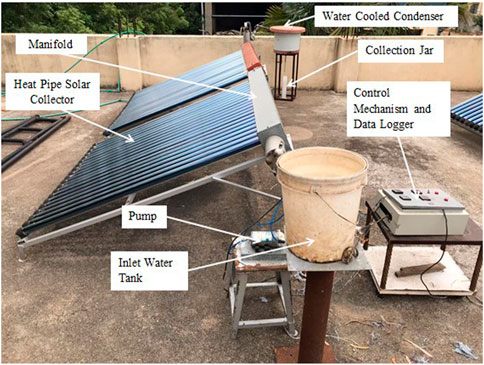
FIGURE 1. Pictorial representation of the evacuated tube solar collector with collective condenser heat pipe solar desalination system.
In ETSC-CCHPSD, each solar module of the collector contains 20 evacuated glass tubes. The two solar collector modules are supported by a mild steel frame. Both the collectors are inclined at an angle equal to the latitude of the location for receiving maximum solar rays. The evacuated glass tube solar collectors were attached with a newly designed arrangement of heat pipes called the collective condenser heat pipe. The newly developed collective condenser heat pipe system is responsible for converting water directly to steam. The main distinguishing features of the newly developed solar collector presented in this study over the previously designed arrangements of heat pipes are as follows:
• The evaporator unit of the heat pipe used in the presented system is connected to a single collective condenser unit of the heat pipe. Two sets of heat pipe systems are used in the study such that each set is placed separately in the evacuated glass tube collector module.
• The evaporator unit of the heat pipe in one module contains 20 tubes. All 20 tubes of evaporator units are affixed with a single condenser unit of the heat pipe. A heat pipe evaporator unit was placed inside the evacuated glass tubes.
• Two heat pipe sets are joined together and act as a single unit of the heat pipe.
• A water flow pipe is placed inside the condenser unit of the heat pipe to facilitate the developed heat inside the heat pipe, which will be transferred to the water directly and uniformly from all directions.
• The solar collector header unit is a combination of a heat pipe condenser part and a water flow pipe.
• The heat pipe working fluid used during the study was water, which is filled inside the heat pipe evaporator unit.
• Insulation of polyurethane foam was used to minimize the heat loss from the collector header section by covering the entire collective condenser unit.
• Fins were connected to evaporator pipes of the heat pipes kept inside the evacuated glass tubes to be used to enhance the rate of heat transfer.
An RO pump and water control mechanism are used to feed the brackish water inside the water pipe. A valve is provided to the header section of the system to remove the saline residual which is left inside the water pipe.
2.2 Instrumentation and experimental procedure
Table 1 shows the specifications of the instruments used in the study. Water was supplied to the ETSC-CCHPSD system using an RO pump of 60 W.
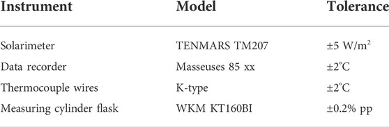
TABLE 1. Specification of the used instruments.
The experimental setup contains two evacuated tube collective condenser heat-pipe solar collectors, a water flow pipe, a control mechanism, an inlet water tank, a water-cooled condenser tank, a measuring flask, and a data acquisition system. Table 2 represents the detailed specification of the ETSC-CCHPSD system.
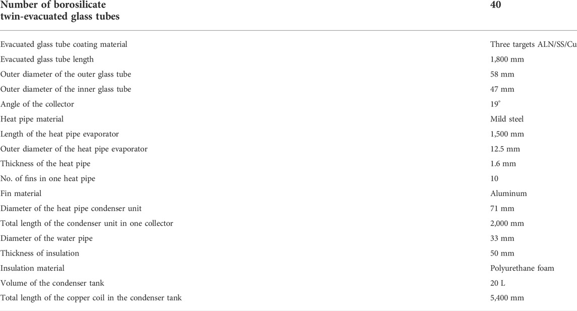
TABLE 2. Specification of the ETSC-CCHPSD desalination system.
The graphic representation of ETSC-CCHPSD is shown in Figure 2. The experimental work of ETSC-CCHPSD was analyzed at the two different modes of the water level in the water pipe of the solar collector. Level TF is a three-fourth filled water pipe (2.1L), and level HF is a half-filled water pipe (1.4 L).
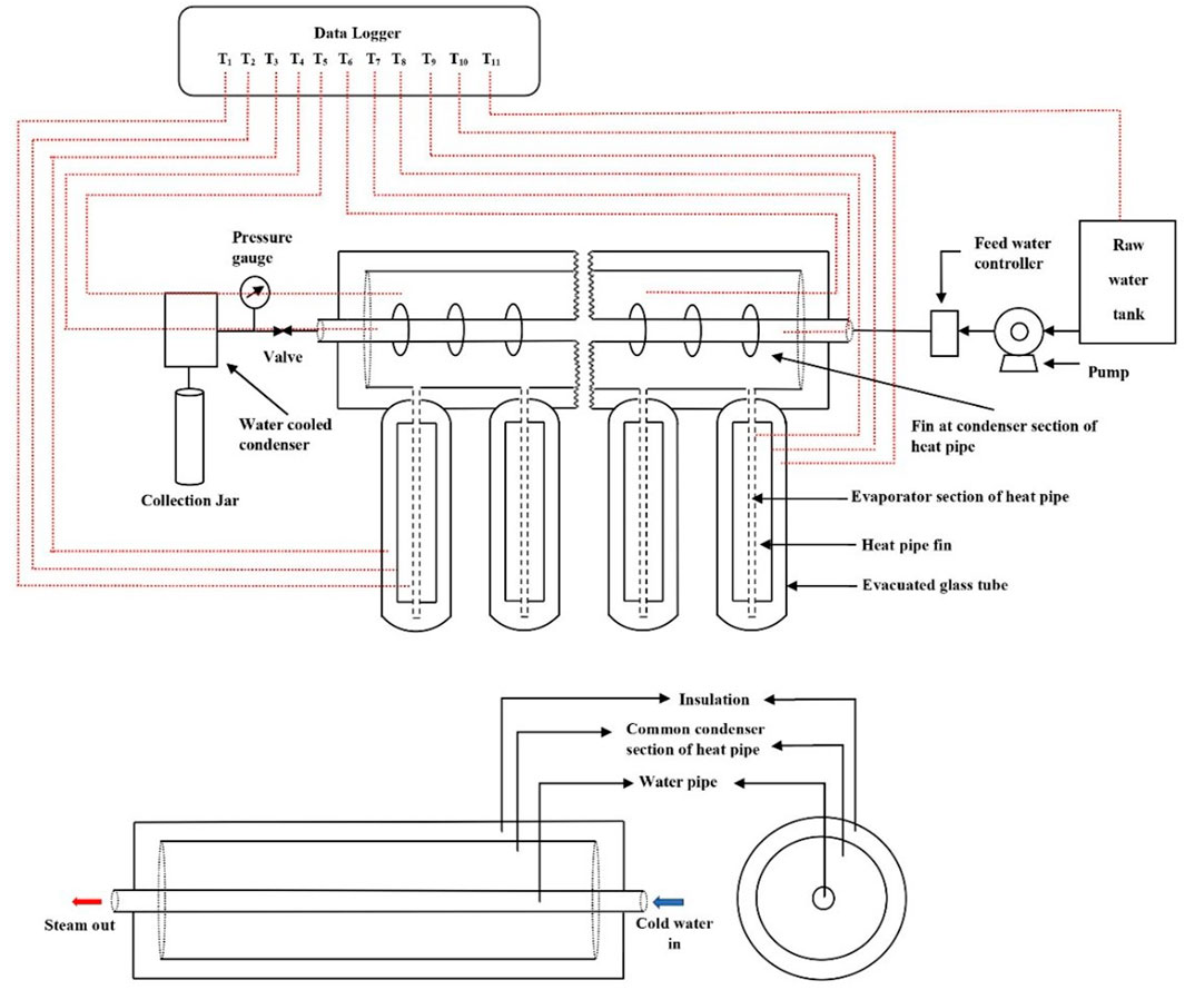
FIGURE 2. Graphic representation of the ETSC-CCHPSD system.
As solar radiation descends on the evacuated glass tubes, it will increase the internal temperature of the evacuated glass tubes. This heat is directly transferred to the heat pipe, which results in the vaporization of water existing in the evaporator unit of the heat pipe as a working fluid. The generated vapor moves to the collective condenser unit and occupies the entire condenser unit volume. The heat is then directly transferred to the water flowing through the water flow pipe placed inside the heat pipe condenser unit. Thus, water in the water flow pipe will be converted to vapor. The generated water vapor exits the ETSC-CCHPSD system and enters the water-cooled condenser unit. The cold water which is present in the condenser absorbs the heat of vapor. Thus, the vapor was converted into water droplets and collected in the measuring flask as distilled water. The hot water present in the water-cooled condenser is changed occasionally for a better heat transfer rate. After completion of the experimentation, the residual water which is present inside the water pipe will be removed for cleaning purposes through the valve. The flow of brackish water to the solar collector was maintained by a feedwater mechanism through a pump.
2.3 Scope and novelty
The stand-alone system was introduced to eliminate a solar collector and still. Freshwater formation was carried out in a new desalination system which acts as a solar collector and a basin for brackish water.
The only single collective condenser heat pipe unit was attached to all the evaporator tube heat pipe units. Each heat pipe evaporator unit was attached to the evacuated tube solar collector.
This new assembly of the heat pipe provides uniform heating of water and an augmented rate of heat transfer, resulting in increased yield. Steam was directly generated into the collector, and the steam was condensed inside a water-cooled condenser to produce distilled water.
3 Energy, exergy, economic, and environmental study of ETSC-CCHPSD
3.1 Energy analysis
The energy and exergy study of the ETSC-CCHPSD system has been elaborated in this section, and the following assumptions were made during the analysis (Daghigh and Shafieian, 2016; Shafieian et al., 2019):
• The temperature variation was considered only in the radial direction.
• All equations were applicable for steady-state flow conditions.
• Kinetic and potential energies are negligible.
• There were no chemical or nuclear reactions occurring in the system.
• The specific heat capacity of water was constant.
• The direction of heat transfer toward the system is positive.
3.1.1 Solar collector
Figure 3 shows the solar radiation absorption and heat loss process, which occurred in the solar collector and heat pipe, respectively. Evacuated glass tubes absorb part of the sunrays which were incident on it. This heat was absorbed by the heat pipe evaporator unit. The heat transfer fluid was evaporated, and the vapor was filled into the heat pipe condenser unit. The heat from the vapor in the condenser unit was directly transferred to the brackish water and again comes back to the evaporator unit, and this cycle continues till solar rays were incident on the glass tubes.
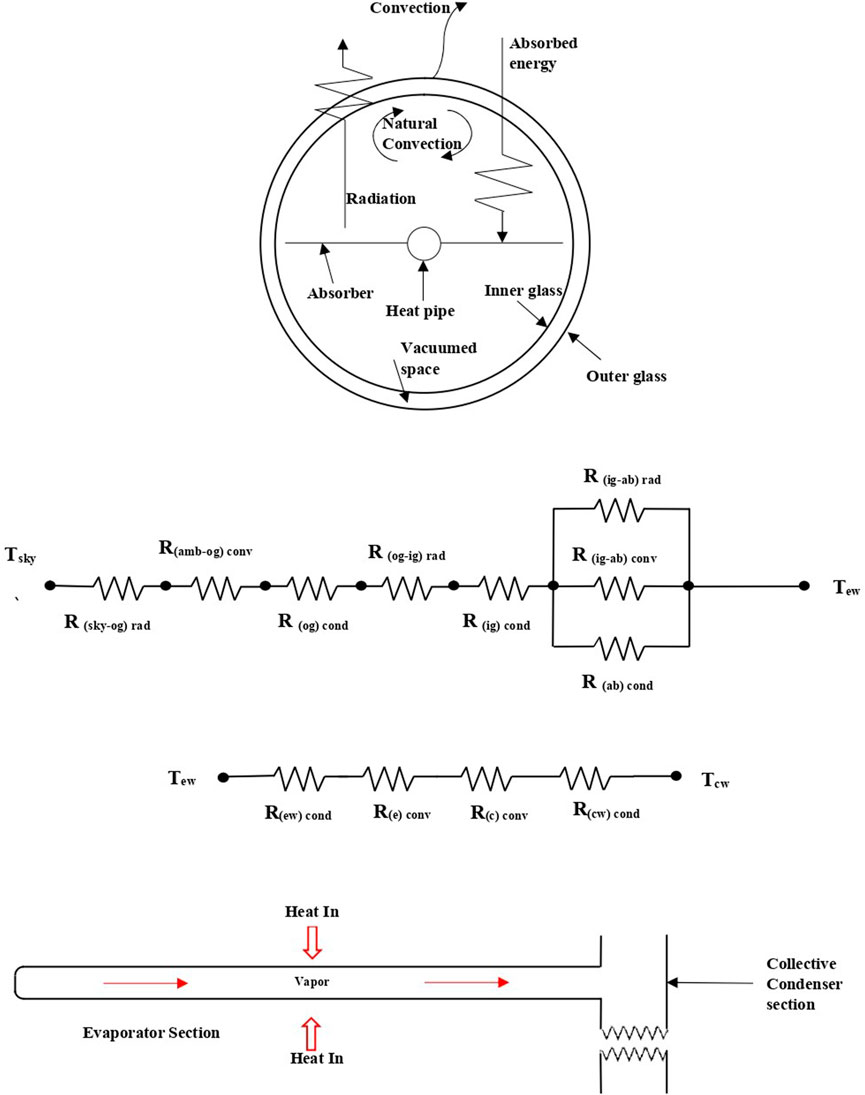
FIGURE 3. Thermal energy balance and resistance in the ETSC-CCHPSD system.
Theoretical energy balance is described by the following equations.
Eq. 1 shows the solar radiation absorbed by the spherical surface of the evacuated glass tube. The total heat absorbed is the difference between the total heat energy entering (Qen) the evacuated glass tube and the heat loss to the atmosphere (Qloss) (Wang et al., 2012).
where Eq. 2 represents Qen which is the solar radiation entering the evacuated glass tube solar collector and Qloss is the loss of energy to the atmosphere (Eq. 3) (Azad, 2008; Daghigh and Shafieian, 2016).
Rt is the thermal resistance (Figure 3) and is calculated as follows (Azad, 2008; Dunn and Reay, 2016):
where RETC can be represented as
The sky is assumed as a black body, so emissivity is assumed as one (Hlaing and Soe, 2014).
The sky temperature can be calculated by Eq. 7
Convective resistance determined between the external twin evacuated glass tube and ambient is (Chopra et al., 2019)
The convective heat transfer coefficient is determined as follows (Hlaing and Soe, 2014):
Conduction thermal resistance due to the outer glass tube can be represented as (Chopra et al., 2019)
The radiation thermal resistance is present between the outer and inner glass tube (Daghigh and Shafieian, 2016).
The thermal resistance due to conduction for the inner glass tube is calculated as
Convection thermal resistance between the absorber and inner glass tube can be represented as (Chopra et al., 2019)
The radiation thermal resistance between the absorber and inner glass tube is given by (Dunn and Reay, 2016; Chopra et al., 2019)
A conduction thermal loss between the absorber and inner borosilicate glass tube can be represented as (Cengel, 2007)
3.1.2 Heat pipe
In this work, heat pipes were used to transfer the absorbed heat energy of the Sun to the water by the evacuated glass tubes. The overall thermal resistance generated by the heat pipe is the sum of conduction and convection thermal resistance present in the evaporator and condenser. Eq. 16 is used to evaluate it.
Conduction thermal resistance due to the evaporator wall and condenser wall can be calculated as follows (Azad, 2008; Daghigh and Shafieian, 2016):
The thermal resistance offered by the flow of the heat transfer fluid in the evaporator and condenser unit of the heat pipe during the process of evaporation and condensation is given as (Azad, 2008; Daghigh and Shafieian, 2016)
3.1.3 Energy efficiency
The heat absorbed by the brackish water and collector efficiency may be calculated by Eq. 23 and Eq. 24, respectively. The energy efficiency (ƞ) of the system is the ratio of the amount of heat absorbed by the brackish water to the amount of heat absorbed by the collector (Cengel, 2007).
3.2 Exergy analysis
Eq. 25 shows the exergy of the ETSC-CCHPSD system. It is the ratio of the desired output to the maximum possible output (Gupta and Kaushik, 2010; Kumar et al., 2014).
3.3 Economic analysis
This section elaborates on the economic study of ETSC-CCHPSD. The financial viability of the ETSC-CCHPSD system was determined based on the unit cost of desalination and payback period. The unit cost of desalination depends on parameters such as capital cost, annual rate of interest, life of the desalination unit, salvage value, yearly productivity, and yearly operation and maintenance cost. Table 3 shows the parameters considered for the economic analysis of ETSC-CCHPSD (Ranjan and Kaushik, 2016).
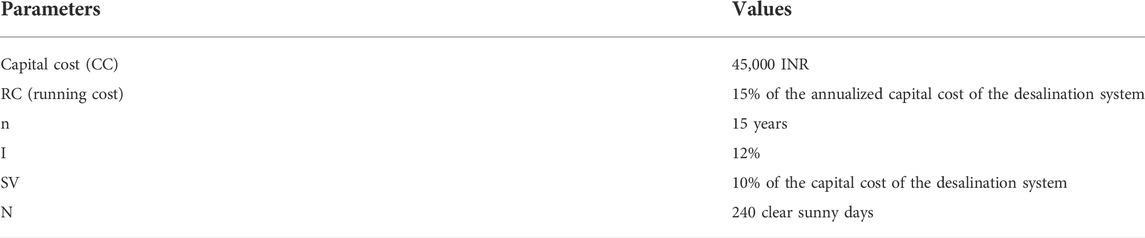
TABLE 3. Parameters for economic analysis.
The unit cost for desalination of brackish water is calculated as follows:
The yearly cost of the ETSC-CCHPSD system is determined as
where the capital salvage factor (CSF) is calculated as
The annual salvage value (ASV) can be calculated as the product of the salvage value (SV) and the sinking fund factor (SFF).
where
The average yearly mass of distilled water produced can be evaluated as
where md is the average daily production of the ETSC-CCHPSD system and Nd is the total number of sunny days in a year.
The payback period of the ETSC-CCHPSD system is calculated as
Cash flow (CF) can be calculated if the distilled water, which is produced by the present desalination system, is sold in the market.
3.4 Environmental impact analysis
The conversion of saline water into freshwater requires energy which can be either a renewable or non-renewable source. The non-renewable source degrades the environment by emitting harmful gases which cause global warming and increases the Earth’s atmospheric temperature. It is a great advantage to save our planet by using renewable sources of energy. The present system is one step toward this revolution, and it was compared with the RO system to calculate energy savings and earned carbon credits. The RO systems produce low-price freshwater at high environmental degradation costs.
Indian power plants emit 0.8–0.9 kg/kWh CO2 for the generation of electricity (Ranjan and Kaushik, 2016). In this study, 0.98kg/kWh is considered the CO2 equivalent. This is assumed as the CO2 equivalent impact factor for other greenhouse gases in this study. The RO system consumes 0.4–7.0 kWh/m3 electricity to remove the total dissolved salts from raw water in the range of 10,000–40,000 ppm to 500 ppm in the freshwater (Ranjan and Kaushik, 2016). In this study, a 2.5 kWh/m3 electricity consumption is assumed for a small-scale RO system in which the ETSC-CCHPSD is used instead of the RO system to calculate energy saving and earned carbon credits (Ranjan and Kaushik, 2016).
4 Results and discussion
The experimental examination of ETSC-CCHPSD was analyzed at the two different mode levels of water in the water pipe of the solar collector. Level TF is a three-fourth-filled water pipe, and level HF is a half-filled water pipe. The fluctuation of solar irradiance and temperature of the ambient, evacuated tube and heat was analyzed during the study. Thermal (energy and exergy), economic, and environmental analyses were also compiled during the study.
4.1 Variation of solar irradiance
The solar radiation intensity was measured at 30-min time intervals during the study. Figure 4 shows the average solar radiation intensity recorded during the experiments conducted during levels TF and HF of the study. Solar radiation intensity was recorded from morning 9 a.m. to evening 5 p.m. It was observed that the pattern in the variation in the solar radiation intensity was similar during levels TF and HF. The average solar radiation recorded during level TF and level HF was 799.71 W/m2 and 814.42 W/m2, respectively. The maximum solar radiation received during level TF and level HF of the study was 1014 W/m2 and 1072 W/m2, respectively, at 1 p.m. After 1 p.m., the solar radiation intensity shows a decrement trend. Kumar et al. reported the same trend of solar radiation and achieved maximum solar intensity at 12.00 p.m. (Kumar et al., 2020).
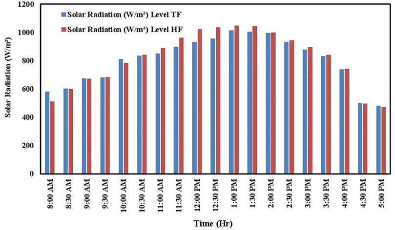
FIGURE 4. Solar radiation intensity with time.
4.2 Temperature profile of the ETSC with time
The average temperature of the ambient, evacuated tube, heat pipe evaporator, and condenser unit is shown in Figure 5. All the temperature readings were taken using K-type thermocouples connected at different locations of the system. The maximum temperature measured inside the evacuated glass tube and heat pipe evaporator unit was 161.8°C and 151.5°C, respectively, at 1.00 p.m. for level TF, and during level HF, the maximum temperature measured inside the evacuated glass tube and heat pipe evaporator unit was 165°C and 156.9°C, respectively, at 1.30 p.m. The higher temperature inside the evacuated glass tubes is due to the minimum conductive and convective heat losses from the evacuated glass tube. The maximum heat pipe condenser temperature observed was 111.6°C and 115.4°C for level TF and level HF at 1.00 p.m. and 1.30 p.m., respectively. This is because of the variation in the quantity of water present inside the water pipe of the system during levels TF and HF. The collective condenser heat pipe system used in the study and the perfect insulation given to the system also helped in retaining heat within the system. The average evacuated tube temperature during level TF and level HF was achieved at 130.71°C and 134.78°C respectively. The average heat pipe evaporator temperature during Level TF and Level HF recorded was 119.07°C and 124.04°C, respectively. The average heat pipe condenser temperature during level TF and level HF was 97.06°C and 101.32°C, respectively.
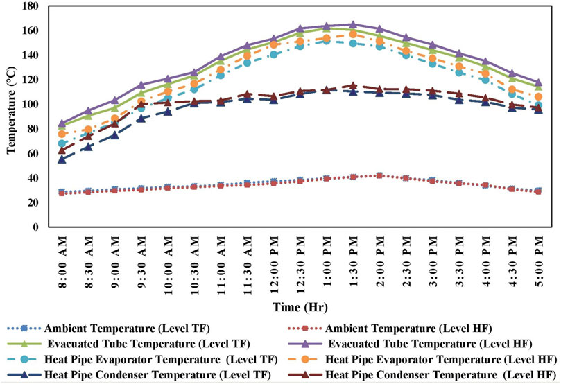
FIGURE 5. Temperature distribution profile with time.
The ambient temperature recorded during the study varied from 27°C to 43°C, with an average temperature of 34.96°C for level TF and 34.14°C for level HF. Adarsh et al. developed a solar air dryer integrated with the 20 ETC. The reported average ambient and ETC temperatures were found to vary from 34 to 36°C and 80–88°C, respectively, during different air mass flow rates. The lower value of the ETC temperature was due to the small collector area and heating of air (Mathew and Venugopal, 2021).
4.3 Productivity
The freshwater delivered by the system is measured with the help of a measuring flask at 30-min time intervals. Figure 6 represents the productivity of freshwater from the system during Level TF and Level HF. The maximum quantity of distilled water was obtained between 1 p.m. and 2 p.m. in both cases. This is because the maximum solar radiation intensity was recorded during this period. From the study, it was observed that the quantity of distilled water was more when solar radiation intensity, the temperature of the evacuated tube, the temperature of the heat pipe evaporator, and the collective condenser unit were maximum. The daily distilled water output measured from the ETSC-CCHPSD system during level TF and level HF was 5,925 ml and 8,050 ml, respectively. During level HF, the amount of freshwater is more because of maintaining of a low water level inside the water pipe. Due to this, the rate of evaporation was faster in level HF. The rate of evaporation was enhanced due to the fewer thermal resistances observed during level HF. As the evaporation of water increases, the amount of freshwater also increases. Another advantage of the ETSC-CCHPSD system is that it generates both distilled water and hot water. The system generates hot water during the condensation of steam. The water vapor exiting the ETSC-CCHPSD system releases its heat into the cooling water present inside the water-cooled condenser, and this hot water can be used for other daily activities. The ETSC-CCHPSD system produces approximately 40 L and 55 L of hot water for level TF and level HF, respectively, with an average water temperature of 70 °C. As the rate of evaporation increased, a high amount of water was required to condense the vapor in the water-cooled condenser. The higher quantity of hot water obtained during level HF was due to the higher quantity of water present inside the water-cooled condenser.
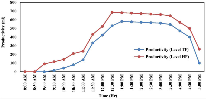
FIGURE 6. Productivity of distilled water with time.
Table 4 shows the daily productivity comparison of ETSC-CCHPSD with previously designed desalination systems. The comparison study of ETSC-CCHPSD with other desalination systems shows that the present system gives more productivity. The maximum daily distilled water production recorded from the current system was 8,050 ml/day.
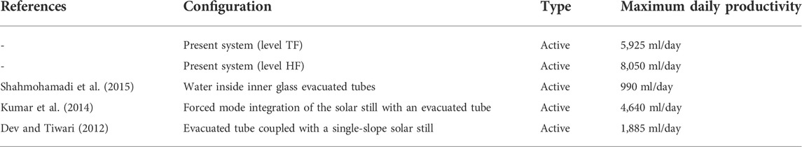
TABLE 4. Performance comparison based on daily productivity.
4.4 Energy and exergy analysis
Thermal energy and exergy efficiency analysis of the ETSC-CCHPSD system at levels TF and HF is explained in this section. Figure 7 and Figure 8 show the hourly energy and exergy efficiencies during levels TF and HF of the ETSC-CCHPSD system, respectively. From the graph, it was observed that the energy efficiency starts to increase from 8.00 a.m. and reached its maximum value at 4 p.m. The maximum energy efficiency delivered by ETSC-CCHPSD was 14.3% and 19.27% during level TF and level HF, respectively. The increased quantity of water inside the water pipe decreases the thermal efficiency of the system. This is due to the high heat transfer rate between the water and condenser fluid of the heat pipe during less quantity of water. During water evaporation, less quantity of water gets sufficient time to absorb the heat of the heat pipe. The average energy efficiency of ETSC-CCHPSD during level TF and level HF was 7.64% and 10.33%, respectively.
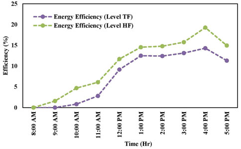
FIGURE 7. Hourly energy efficiency variation with time.
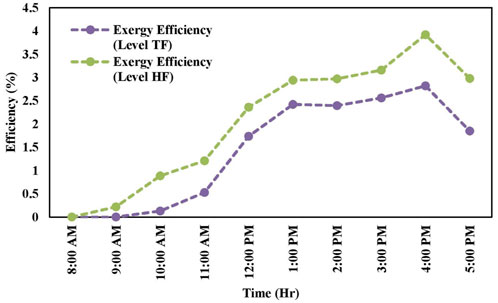
FIGURE 8. Hourly exergy efficiency variation with time.
The exergy efficiency of ETSC-CCHPSD is high when less quantity of water was present inside the water pipe. The maximum exergy efficiencies obtained during level TF and level HF were 2.82% and 3.92%, respectively. From Figure 9 it was also identified that energy efficiency is more than the exergy efficiency in both cases. This is due to the removal and loss of exergy in the system.
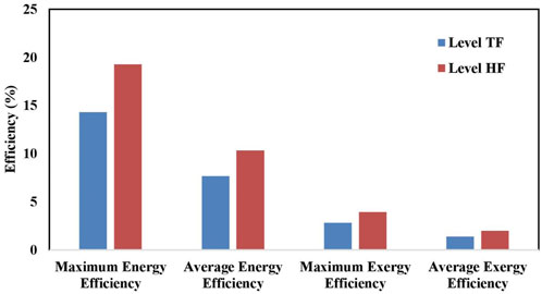
FIGURE 9. Maximum and average value of energy and exergy efficiency.
4.5 Thermal resistances
Table 5 represents the thermal resistance parameters obtained during the analysis for both cases. Evacuated glass tubes are made up of borosilicate glass, and a vacuum is present between two tubes. Due to this, it was observed that very low thermal resistance was offered by the system. The variation in thermal resistance during level TF was slightly higher than that in level HF. Higher values of level TF were due to the variation of ambient conditions during experimentation and the variation of water quantity present inside the system. It was also observed that no significant changes in the overall thermal resistance were observed due to the evacuated glass tube and heat pipe during both cases.
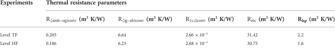
TABLE 5. Thermal resistance parameters of the evacuated glass tube and heat pipe.
4.6 Economic analysis
This section elaborates on an economic analysis of ETSC-CCHPSD. It includes the total cost of fresh water and electricity used for running this system. The operating period of ETSC-CCHPSD was taken as 9 h/day and 240 clear sunny days in a year. An RO pump of 60 W power was used for adding water into the system. The average power consumed per day by the pump is very low due to non-continuous operation. The capital cost of the system is 45,000 INR, and the annualized capital cost of the system derived was 6,607.091 INR. The unit cost of freshwater delivered by ETSC-CCHPSD under level TF and level HF was obtained as 5.11 INR and 4.27 INR, respectively. The payback period of ETSC-CCHPSD was 4.2 years and 2.9 years for level TF and level HF, respectively. The selling price of water for 1 L in the market was assumed as 10 INR. The economic study of ETSC-CCHPSD shows that the system is capable of delivering fresh water at a cheaper rate than the fresh water available in the market. Table 6 shows the economic analysis parameters considered during the study.
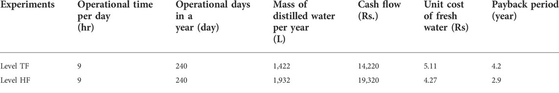
TABLE 6. Economic analysis parameters.
4.7 Environmental impact analysis
The impact of the present ETSC-CCHPSD system on the environment was analyzed by calculating earned carbon credits. To estimate the earned carbon credits from ETSC-CCHPSD, a comparison study was conducted with a small-scale RO system. The present ETSC-CCHPSD system saves approximately 3.55 kWh and 4.25 kWh electricity during level TF and level HF, respectively, instead of using an RO system for 1422 L/y and 1932 L/y freshwater for level TF and level HF, respectively. In the open market, the salable carbon credit is known as CER (1 CER = ton of CO2). The present ETSC-CCHPSD system earns approximately 3.48 × 10⁻³ and 4.16 × 10⁻³ tons of CO2 equivalent for level TF and level HF, respectively. The present system is considered an environmentally friendly and high-grade energy saving system.
5 Conclusion
This research article discusses the development of a new novel desalination system using an evacuated tube collector integrated with a single collective condenser heat pipe. The scope of the article analyzes the thermodynamic and economic aspects of the developed system and how it is environmental-friendly with negligible pollution on the basis of its earned carbon credit. The following findings were observed based on the experiment conducted on the ETSC-CCHPSD system:
• This novel ETSC-CCHPSD was used as a basin and a collector at the same time. So, this system utilizes space effectively.
• The maximum temperature in the evacuated glass tube and the heat pipe evaporator recorded was 161.8°C and 151.5°C, respectively, at 01.00 p.m. for level TF. The maximum temperature in the evacuated glass tube and the heat pipe evaporator was 165°C and 156.9°C, respectively, at 01.30 p.m. for level HF.
• The highest heat pipe condenser temperature obtained was 111.6°C and 115.4°C at a maximum solar radiation intensity of 1,014.7 W/m2 and 1,048 W/m2 during level TF and level HF, respectively.
• The daily productivity of ETSC-CCHPSD during level TF and level HF was 5,925 ml and 8,050 ml, respectively. The maximum freshwater productivity was achieved between 1 p.m. and 2 p.m.
• The higher the solar radiation intensity, the higher will be the distillate yield from ETSC-CCHPSD.
• Energy efficiency improvement of 35.86% was identified in level HF as compared to level TF. This improvement is due to the less quantity of water present inside the water pipe.
• The ETSC-CCHPSD system delivers freshwater and hot water at the same time. The system produced 40 L and 55 L of hot water during level TF and level HF, respectively, at a maximum temperature of 70°C.
• The maximum energy and exergy efficiency of ETSC-CCHPSD during level TF was 14.3% and 2.82%, and for level HF, it was 19.27% and 3.92%, respectively.
• The unit cost of freshwater from ETSC-CCHPSD was 5.11 and 4.27 INR during level TF and level HF, respectively. The payback period for ETSC-CCHPSD is calculated as 4.2 and 2.9 years for level TF and level HF, respectively.
• 3.48 × 10⁻³ and 4.16 × 10⁻³ tons of CO2 equivalent are saved by the present system during level TF and level HF, respectively.
Overall, it can be concluded that the present system works effectively when the water flow pipe is half-filled. The present system can deliver both distilled and hot water together, which is an added benefit of the system. The new heat pipe arrangement adopted during the study helped in uniform and faster heating of water. ETSC-CCHPSD is an eco-friendly device.
Data availability statement
The original contributions presented in the study are included in the article/Supplementary Material; further inquiries can be directed to the corresponding author.
Author contributions
Both the authors contributed to the concept, design, and development of the present work. In addition, this work was carried out as a part of Ph.D. dissertation of GN who was supervised by KK. GN performed the experimental and numerical analyses, collected and interpreted the data, and drafted the majority of the manuscript. KK supervised and revised all the data interpretation, analyses, and manuscript.
Conflict of interest
The authors declare that the research was conducted in the absence of any commercial or financial relationships that could be construed as a potential conflict of interest.
Publisher’s note
All claims expressed in this article are solely those of the authors and do not necessarily represent those of their affiliated organizations, or those of the publisher, the editors, and the reviewers. Any product that may be evaluated in this article, or claim that may be made by its manufacturer, is not guaranteed or endorsed by the publisher.
References
Abdel-Rehim, Z. S., and Lasheen, A. (2007). Experimental and theoretical study of a solar desalination system located in Cairo, Egypt. Desalination 217 (1-3), 52–64. doi:10.1016/j.desal.2007.01.012
Arunkumar, T., Velraj, R., Denkenberger, D. C., Sathyamurthy, R., Kumar, K. V., and Ahsan, A. (2016). Productivity enhancements of compound parabolic concentrator tubular solar stills. Renew. energy 88, 391–400. doi:10.1016/j.renene.2015.11.051
Azad, E. (2008). Theoretical and experimental investigation of heat pipe solar collector. Exp. Therm. Fluid Sci. 32 (8), 1666–1672. doi:10.1016/j.expthermflusci.2008.05.011
Badran, A. A., Al-Hallaq, I. A., Salman, I. A. E., and Odat, M. Z. (2005). A solar still augmented with a flat-plate collector. Desalination 172 (3), 227–234. doi:10.1016/j.desal.2004.06.203
Chakraborti, R. K., Kaur, J., and Kaur, H. (2019). Water shortage challenges and a way forward in India. J. Am. Water Works Assoc. 111, 42–49. doi:10.1002/awwa.1289
Chen, Q., Alrowais, R., Burhan, M., byraiymkul, D., Shahzad, M. W., Li, Y., et al. (2020). A self-sustainable solar desalination system using direct spray technology. Energy 205, 118037. doi:10.1016/j.energy.2020.118037
Chopra, K., Tyagi, V. V., Pandey, A. K., Sari Ahmet Chopra, K., Tyagi, V. V., Pandey, A. K., et al. (2018). Global advancement on experimental and thermal analysis of evacuated tube collector with and without heat pipe systems and possible applications. Appl. energy 228, 351–389. doi:10.1016/j.apenergy.2018.06.067
Chopra, K., Tyagi, V. V., Pathak, A. K., Pandey, A. K., and Sari, A. (2019). Experimental performance evaluation of a novel designed phase change material integrated manifold heat pipe evacuated tube solar collector system. Energy Convers. Manag. 198, 111896. doi:10.1016/j.enconman.2019.111896
Daghigh, R., and Shafieian, A. (2016). Theoretical and experimental analysis of thermal performance of a solar water heating system with evacuated tube heat pipe collector. Appl. Therm. Eng. 103, 1219–1227. doi:10.1016/j.applthermaleng.2016.05.034
Dev, R., and Tiwari, G. N. (2012). Annual performance of evacuated tubular collector integrated solar still. Desalination water Treat. 41 (1-3), 204–223. doi:10.1080/19443994.2012.664715
Garcia-Rodriguez, L. (2007). Assessment of most promising developments in solar desalination. Sol. desalination 21st century, 355–369. doi:10.1007/978-1-4020-5508-9_26
Gupta, M. K., and Kaushik, S. C. (2010). Exergy analysis and investigation for various feed water heaters of direct steam generation solar–thermal power plant. Renew. Energy 35 (6), 1228–1235. doi:10.1016/j.renene.2009.09.007
Hlaing, S., and Soe, M. M. (2014). Design calculation and heat transfer analysis of heat pipe evacuated tube solar collector for water heating. Int. J. Sci. Eng. Technol. Res. (IJSETR) 3 (12), 2606–2611.
Kabeel, A. E., Abdelgaied, M., and Mahgoub, M. (2016). The performance of a modified solar still using hot air injection and PCM. Desalination 379, 102–107. doi:10.1016/j.desal.2015.11.007
Kabeel, A. E., and Abdelgaied, M. (2017). Observational study of modified solar still coupled with oil serpentine loop from cylindrical parabolic concentrator and phase changing material under basin. Sol. Energy 144, 71–78. doi:10.1016/j.solener.2017.01.007
Kaushal, A., and Varun, (2010). Solar stills: A review. Renew. Sustain. Energy Rev. 14 (1), 446–453. doi:10.1016/j.rser.2009.05.011
Kumar, A., Vyas, S., and Nkwetta, D. N. (2020). Experimental study of single slope solar still coupled with parabolic trough collector. Mater. Sci. Energy Technol. 3, 700–708. doi:10.1016/j.mset.2020.07.005
Kumar, K. V., and Bai, R. (2008). Performance study on solar still with enhanced condensation. Desalination 230, 51–61. doi:10.1016/j.desal.2007.11.015
Kumar, S., Dubey, A., and Tiwari, G. N. (2014). A solar still augmented with an evacuated tube collector in forced mode. Desalination 347, 15–24. doi:10.1016/j.desal.2014.05.019
Mathew, A. A., and Venugopal, T. (2021). A novel thermal storage integrated evacuated tube heat pipe solar air heater: Energy, exergy, economic and environmental impact analysis. Sol. Energy 220, 828–842. doi:10.1016/j.solener.2021.03.057
Mosleh, H. J., Mamouri, S. J., Shafii, M. B., and Sima, A. H. (2015). A new desalination system using a combination of heat pipe, evacuated tube and parabolic trough collector. Energy Convers. Manag. 99, 141–150. doi:10.1016/j.enconman.2015.04.028
Muraleedharan, M., Singh, H., Udayakumar, M., and Suresh, S. (2019). Modified active solar distillation system employing directly absorbing Therminol 55–Al2O3 nano heat transfer fluid and Fresnel lens concentrator. Desalination 457, 32–38. doi:10.1016/j.desal.2019.01.024
Nagarajan, P. K., El-Agouz, S. A., Harris, S. D. G., Edwin, M., Madhu, B., Magesh Babu, D., et al. (2017). Analysis of an inclined solar still with baffles for improving the yield of fresh water. Process Saf. Environ. Prot. 105, 326–337. doi:10.1016/j.psep.2016.11.018
Negi, A., Dhindsa, G. S., and Sehgal, S. S. (2022). Experimental investigation on single basin tilted wick solar still integrated with flat plate collector. Mater. Today Proc. 48 (5), 1439–1446. doi:10.1016/j.matpr.2021.09.210
Nema, G., and Karunamurthy, K. (2021). A comprehensive review on the productivity enhancement of a solar desalination system through parameters and techniques. IOP Conf. Ser. Earth Environ. Sci. 850, 012040. doi:10.1088/1755-1315/850/1/012040
Ranjan, K. R., and Kaushik, S. C. (2016). Economic feasibility evaluation of solar distillation systems based on the equivalent cost of environmental degradation and high-grade energy savings. Int. J. Low-Carbon Tech. 11 (1), ctt048–15. doi:10.1093/ijlct/ctt048
Sathyamurthy, R., Samuel, D. H., and Nagarajan, P. K. (2016). Theoretical analysis of inclined solar still with baffle plates for improving the fresh water yield. Process Saf. Environ. Prot. 101, 93–107. doi:10.1016/j.psep.2015.08.010
Shafieian, A., Khiadani, M., and Nosrati, A. (2019). Thermal performance of an evacuated tube heat pipe solar water heating system in cold season. Appl. Therm. Eng. 149, 644–657. doi:10.1016/j.applthermaleng.2018.12.078
Shafii, M. B., Mamouri, S. J., Lotfi, M. M., and Mosleh, H. J. (2016). A modified solar desalination system using evacuated tube collector. Desalination 396, 30–38. doi:10.1016/j.desal.2016.05.030
Shahmohamadi, M., Shafii, M. B., and Sadrhosseini, H. (2015). (Pretoria, South Africa: May), 11–13.Solar water distillation by using water in the inner glass evacuated tubes Proceedings of the 3rd Southern African Solar Energy ConferenceSouth Africa, 11-13 May, 2015
Shoeibi, S., Kargarsharifabad, H., Rahbar, N., Khosravi, G., and Sharifpur, M. (2022). An integrated solar desalination with evacuated tube heat pipe solar collector and new wind ventilator external condenser. Sustain. Energy Technol. Assessments 50, 101857. doi:10.1016/j.seta.2021.101857
Singh, A. K., and Samsher, (2022). Techno-environ-economic-energy-exergy-matrices performance analysis of evacuated annulus tube with modified parabolic concentrator assisted single slope solar desalination system. J. Clean. Prod. 332, 129996. doi:10.1016/j.jclepro.2021.129996
Singh, D. B., Yadav, J. K., Dwivedi, V. K., Kumar, S., Tiwari, G. N., and Al-Helal, I. M. (2016). Experimental studies of active solar still integrated with two hybrid PVT collectors. Sol. Energy 130, 207–223. doi:10.1016/j.solener.2016.02.024
Sokhansefat, T., Kasaeian, A., Rahmani, K., Heidari, A. H., Aghakhani, F., and Mahian, O. (2018). Thermoeconomic and environmental analysis of solar flat plate and evacuated tube collectors in cold climatic conditions. Renew. Energy 115, 501–508. doi:10.1016/j.renene.2017.08.057
Tabrizi, F. F., Dashtban, M., and Moghaddam, H. (2010). Experimental investigation of a weir-type cascade solar still with built-in latent heat thermal energy storage system. Desalination 260 (1-3), 248–253. doi:10.1016/j.desal.2010.03.033
Voropoulos, K., Mathioulakis, E., and Belessiotis, V. (2001). Experimental investigation of a solar still coupled with solar collectors. Desalination 138 (1-3), 103–110. doi:10.1016/s0011-9164(01)00251-x
Wang, Z., Duan, Z., Zhao, X., and Chen, M. (2012). Dynamic performance of a facade-based solar loop heat pipe water heating system. Sol. Energy 86 (5), 1632–1647. doi:10.1016/j.solener.2012.02.031
Yadav, Y. P. (1991). Analytical performance of a solar still integrated with a flat plate solar collector Thermosiphon mode. Energy Convers. Manag. 31 (3), 255–263. doi:10.1016/0196-8904(91)90079-x
Yu, T., Feng, Q., Si, J., Zhang, X., Xi, H., and Zhao, C. (2018). Comparable water use of two contrasting riparian forests in the lower Heihe River basin, Northwest China. J. For. Res. (Harbin). 29 (5), 1215–1224. doi:10.1007/s11676-017-0540-2
Nomenclature
A Area (m2)
µ Dynamic viscosity (Pa s)
Cp Specific heat capacity (J/kg.K)
ƞ Efficiency
D Diameter (m)
ρ Density (kg/m3)
F Radiation shape factor
θ Angle
g Glass/acceleration due to gravity (9.81 m/s2)
σ Stefan–Boltzmann constant (5.67 × 10⁻⁸ kg/s3 K4)
h Convective heat transfer coefficient (W/m2 K)
Є Emissivity
I Solar radiation intensity (W/m2)
π pi (3.14)
k Thermal conductivity (W/m2 K)
Subscripts
l Length/liquid/liter
a Air
L Latent heat (J/kg)
ab Absorber/absorbed
M Total mass (kg)
amb Ambient
N Total number
c Collector/coating/condenser
Q Rate of heat transfer (W)
cond Conduction
R Thermal resistance (K/W)
conv Convection
t Total/thickness (m)
e Evaporator
T Temperature (K)
i Inner
V Velocity of air (m/s)
o Outer
Greek letters
rad Radiation
τ Transmittance
v Vapor
α Absorptivity
w Water/wall
Keywords: evacuated tube collector, collective condenser, heat pipe, desalination, energy and exergy, economic and environment impact analysis
Citation: Nema G and Karunamurthy K (2022) A novel solar desalination system based on an evacuated tube collective condenser heat pipe solar collector: A thermo-economic and environmental analysis. Front. Mech. Eng 8:959286. doi: 10.3389/fmech.2022.959286
Received: 01 June 2022; Accepted: 22 September 2022;
Published: 10 October 2022.
Edited by:
Mathew VK, MIT ADT University, IndiaReviewed by:
Amine Moussaoui, Mohamed Premier University, MoroccoShiva Gorjian, Tarbiat Modares University, Iran
Copyright © 2022 Nema and Karunamurthy. This is an open-access article distributed under the terms of the Creative Commons Attribution License (CC BY). The use, distribution or reproduction in other forums is permitted, provided the original author(s) and the copyright owner(s) are credited and that the original publication in this journal is cited, in accordance with accepted academic practice. No use, distribution or reproduction is permitted which does not comply with these terms.
*Correspondence: Garima Nema, Z2FyaW1hLm5lbWEyMDE4QHZpdHN0dWRlbnQuYWMuaW4=