 Zixing Yang1,2
 Xinjiang Liao
- 1Institute of Manufacturing Engineering, Huaqiao University, Xiamen, China
- 2Collaborative Innovation Center of Advanced Manufacturing Technology and Equipment for Stone Industry, Xiamen, China
- 3College of Mechanical Engineering and Automation, Huaqiao University, Xiamen, China
Multi-wire cutting with diamond wire saw has gradually become the main processing method for hard-and-brittle materials due to its small kerf loss and high machining accuracy. However, the diamond wire saw will inevitably suffer wear during the process of machining, and hence affects the quality of the cut surface. In this paper, a wire saw wear model was established, and the wear at different positions on the wire saw was theoretically calculated by correlating the volume of the workpiece removed by the unit wire saw to the wire saw wear. The iteration method was used to calculate the wear of the wire saw after cutting by superimposing the wear caused by every monolithic wafer. Based on this wear year model of the wire saw, the influence of multi-wire cutting parameters and the shapes of the workpiece on the wire saw wear was discussed through numerical simulation. The simulation results showed that the feed speed of the workpiece and the length of the wire saw had an obvious effect on the maximum wear of the wire saw, and the maximum rocking angle, wire speed, and reciprocating times had little effect on the maximum wear of the wire saw. The wear curve of the circular workpiece wire saw is unstable in the whole process, and the wear curve of the rectangular workpiece wire saw changes at the beginning and end, and the middle is stable.
1 Introduction
Wafer slicing is an essential step in the fabricating of electronic device chips, which transforms crystalline materials from sticks to flakes. Multi-wire sawing with diamond wire saw is the main technology used in the semiconductor industry for slicing sapphire (Kim et al., 2013, 2015; Lee et al., 2016), silicon carbide (Maeda et al., 2014; Huang et al., 2016; Wang et al., 2017; Zhao et al., 2021) and silicon ingots (Chen et al., 2019; Sekhar et al., 2020). However, during the multi-wire sawing process, the diamond wire saw would inevitably wear out (Kumar et al., 2016; Knoblauch et al., 2018; Yin et al., 2021).
The wear of a diamond wire saw during the cutting process led to an increase in both cutting and normal forces (Pala et al., 2018). Moreover, the wear changed the surface characteristics of the diamond wire saw and influenced the cutting performance along the ingot location (Kim et al., 2013). Exploring the wear mechanism of diamond wire saw during slicing is of importance to improve the surface quality of the wafer and becomes a research hotspot issue. The wear forms and the surface characteristics of diamond wire saw in single-wire cutting were usually studied by a scanning electron microscope (Gao et al., 2016; Kumar et al., 2016; Liu and Zhu, 2022). The diamond wire saw would experience initial wear, stable wear, and severe wear (Yin et al., 2021). To quantify the wear of diamond wire saw, the wire saw diameter, grit protrusion height, and grit volume was selected as an index to study the wear (Li et al., 2015; Pala et al., 2018; Liu and Zhu, 2022). However, only interval sampling, observation, and wear characterization of the experimental results are carried out for the single-wire cutting process. In the multi-wire cutting process, considering that the diamond wire saw from entering the processing area to exiting the processing area involves the machining of hundreds of wafers, more serious wear of the wire saw would suffer than that of the single-wire cutting process. The wear of the diamond wire saw in the multi-wire cutting process is more complex and difficult to directly observe the wear characteristics for the whole diamond wire saw used. To reveal the wear law of diamond wire saw during the multi-wire cutting process is significant to understanding the formation of the cut quality of wafers. However, little literature was studied on the wear of diamond wire saws for the multi-wire cutting process.
This paper reports the theoretical analysis of the wire saw wear during the multi-wire cutting process with rocking and reciprocating motions. The effects of maximum rocking angle, wire speed, workpiece feed speed, reciprocating times, setting out the length of wire saw, and the workpiece shape on the wear of wire saw were studied.
2 Establishment of wire saw wear model
2.1 Assumptions of the wire saw wear model for multi-wire saw process
Figure 1 illustrates the schematic diagram of multi-wire cutting processing, which includes the reciprocating motion of the diamond wire saw, and the downward feeding and rocking motions of the workpiece. The diamond wire saw forms a wire web through a specific winding method. The distance that a wire saw moves from the middle of a wafer to the middle of an adjacent wafer is Sp.
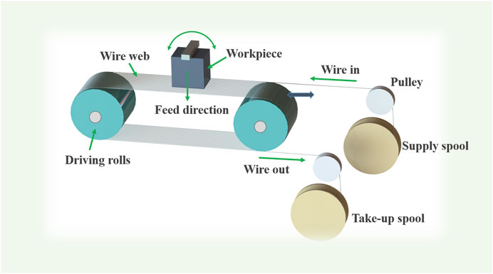
FIGURE 1. The schematic of multi-wire saw cutting.
Illustrates the change in wire speed during the reciprocating motion of the wire saw. The formulas in Eq. 1 describe the movement of the diamond wire saw in each stage shown in Figure 2.
where vs: wire saw speed, vw: maximum wire speed, a: accelerated speed of diamond wire saw (measured as 4 m/s2), L: setting out length per minute, l: setting out length per cycle; f: reciprocating times per minute, tf: the time that the wire saw uniform moves forward in one reciprocating cycle, tb: the time that the wire saw uniform moves backward in one reciprocating cycle, td: the time that the wire speed accelerates to the highest speed or decelerates to zero, T0: the time for one reciprocation of the wire saw. In one cycle of the multi-wire reciprocating diamond, wire saw, the wire feeding time is (2td + tf). After completion, it will make a loop movement, and the loop time is (2td + tb).
where x1: incoming wire saw length in one cycle, x2: loop length in one cycle of the wire saw. Therefore, at the end of one cycle, the length of the used wire saw taken up by the take-up spool is vw (tf - tb), which is also the length of the new wire saw entering the processing area in the next cycle. In the theoretical analysis of wire saw wear, the following assumptions were proposed: ① Assuming that the abrasive particles are evenly distributed on the wire saw, the number of abrasive particles per unit length on the wire saw is the same; ② Assuming that the line starts to enter the processing area, the coordinate system of the line is established. From the position where the workpiece starts to enter the processing, the corresponding coordinate system is also established; ③ Assuming that the diameter of the wire saw is a certain value during the processing, the wire saw has no length deformation, and there is no wire bow during the cutting process; ④ The influence of speed fluctuations on the wear of the wire saw during the acceleration and deceleration process is not considered; ⑤ In the reciprocating process of the wire saw, the removal volume of the workpiece corresponding to each reciprocating cycle is analyzed. Meanwhile, according to the reference (Li et al., 2015), the wear of the wire saw is related to the area processed by the wire saw, which could be described as S by Eq. 3:
where S: the wear degree of the wire saw, p: the volume of the workpiece removed by the wire saw, k: a coefficient reflects the cutting ability of the wire saw, which varies slightly with wear and could be regarded as a constant.
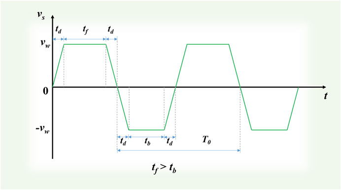
FIGURE 2. The wire saw speed changing with time during the multi-wire saw cutting.
2.2 Wire saw wear model for cutting one rectangular wafer
The area of the workpiece cut by the wire saw per cycle is equal to the area formed by the wire saw track between cycles. The wire saw trajectory can be mainly seen as three segments, which are straight line, arc line, and the straight line (Huang et al., 2016). When the wire saw trajectory was simplified, it can be considered that it consists of three parts, namely, a straight line with symmetrical ends at both ends, and an arc tangent to the straight line. The central angle corresponding to the arc is equal to twice the maximum rocking angle. It is considered that during the reciprocating feeding process of the wire saw, the wire saw trajectories are parallel along the feeding direction.
For the regular shape of the rectangular workpiece, the volume removal per cycle is relatively consistent during the cutting process. Figure 3 illustrates the components of each movement in multi-wire cutting, which are the rocking movement of the workpiece, the feeding movement of the workpiece, and the reciprocating movement of the wire saw. At the same time, it also points out the stable stage of sawing area in one cycle in the process of rectangular workpiece processing. In Figure 3, r is the rocking radius of the workpiece during the rocking process; H is the height of the workpiece relative to the wire saw that the workpiece has been fed by the end of the last reciprocating cycle; ∆H is the height of the workpiece feeding in the next cycle. H is the height of the rectangular workpiece, and l is the width of the rectangular workpiece, as shown in Figure 3.
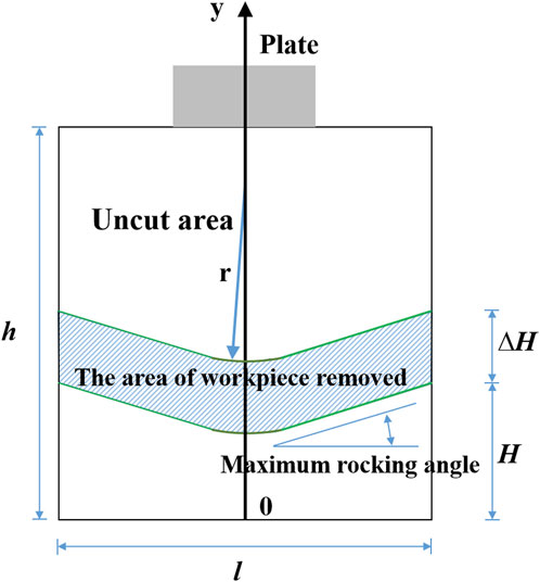
FIGURE 3. Wire saw area chart for a certain period of the rectangular wafer.
The value of pcycle is based on the simplification of the trajectory in the figure shown previously, which is the area formed by the periodic trajectory and the previous periodic trajectory multiplied by the width of the wire saw, that is, the volume is removed.
Figure 4 illustrates a reciprocating cycle of the wire saw is generally divided into two stages (Ⅰ and Ⅱ), namely the wire saw inlet stage and the outlet stage. In the first stage, the workpiece is fed down a distance vw (tf + td). At the end of the second stage, that is, after one cycle, the total downward feed distance of the workpiece is vwT0. The length of the wire saw corresponding to each stage and the volume of the workpiece will be processed in these two stages. Each cycle as a time interval can be used to calculate the volume of the workpiece removed by the wire saw in that cycle. The amount of workpiece volume removed by the wire saw in that cycle is divided by the sum of the reciprocating lengths of the wires involved in machining in that cycle. The removal volume of the workpiece per unit length of the wire saw in this cycle can be obtained.
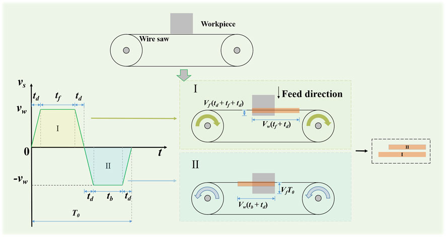
FIGURE 4. Wire movement and wear distribution of wire saw in one reciprocating cycle.
In Figure 5, each color represents the movement of the wire saw in one cycle, and the length of different line segments in the length direction of the wire saw represents the corresponding reciprocating stage when the wire saw reciprocates. The longer one is the incoming line and the shorter one is the return line. The height of each rectangular grid represents the area of workpiece removal in one cycle. In the process of cutting a single wafer, the total wear amount corresponding to each wire saw position is equal to the sum of the heights of all rectangular lattices at their corresponding position, that is, at this position, the wires at all stages of the wire saw processing involved. Wire saw wear is superimposed on the length of the wire. Then, a wire saw wear model for wire sawing a single wafer is obtained.
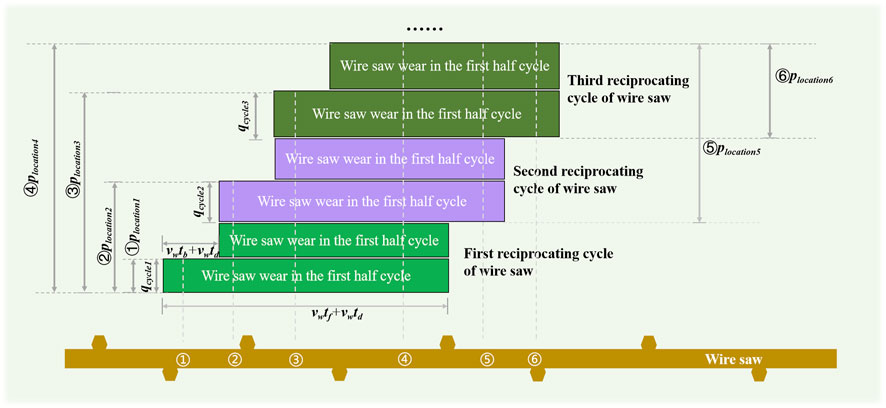
FIGURE 5. Wire movement and wear distribution of wire saw in multiple reciprocating cycles.
Divide the wear amount of the wire saw in this cycle by the length of the wire saw movement in this section, and express the wear amount of the wire saw per unit length of the line as Eq. 4.
where, pcycle: the area of workpiece removal in one cycle, d: the diameter of the wire saw, qcycle: the workpiece removal volume corresponding to the wire saw per unit length in one cycle, i: represents the number of complete reciprocating cycles experienced during sawing.
When using the matrix to calculate the wear amount of the wire, the wire needs to be discretized, the unit wear amount in the interval length is represented by numbers, and the digital interval represents the accuracy of the wire saw wear in the length direction.
The two wear conditions of the wire saw in one cycle are considered to be the same in height. Because without considering the wear of the wire saw, the reason why the height of the wire saw changes in this section of the wire is mainly affected by the parameters, as Eq. 5, but in a cycle, the parameters are unchanged, so in a cycle, the height of the wire saw is also will not change.
According to the expression in Figure 5, calculate Eq. 5, where, n: represents the number of elements used to represent the length of the wire saw calculated by the model after discretizing the length of the wire saw, qcycle is summed to obtain the workpiece removal volume plocation per unit length corresponding to each position on the wire saw. Slocation indicates the wear of the wire saw at this location. Eq. 6 is obtained from Eq. 3. It shows the relationship between plocation and Slocation in the length direction of the discrete wire saw.
2.3 Wire saw wear model for cutting multiple rectangular wafers
Figures 6A, B illustrate that expanding the multi-wire cutting process and can be regarded as the same wire saw, cutting ingots at different intervals at the same time. The interval is related to the machine parameters. Overlay the wire saw wear in Figure 6B together to get the result in Figure 6C.
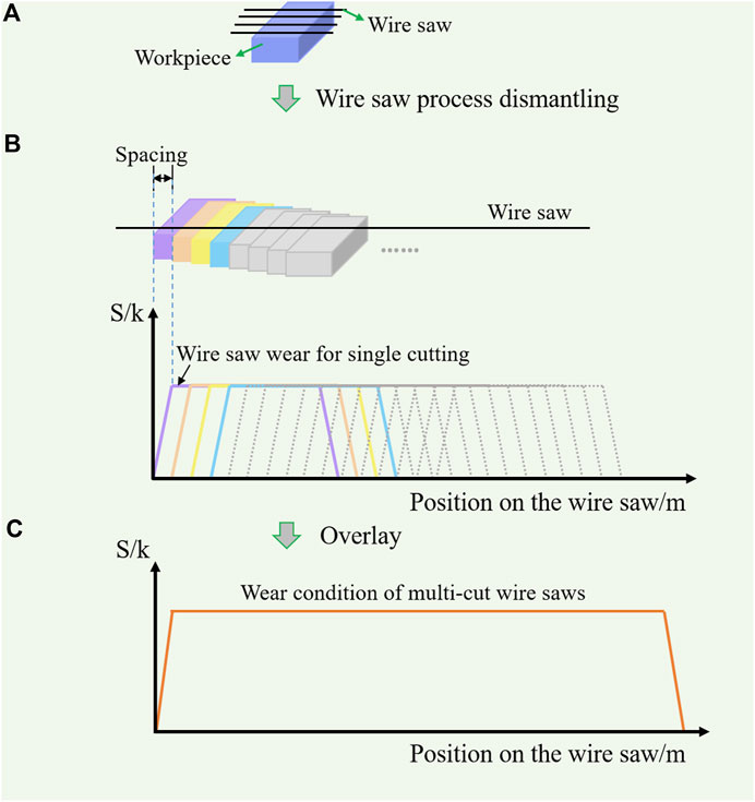
FIGURE 6. Wire saw wear overlay from single wafer to multi-wafer. (A) Schematic diagram of multi-wire sawing, (B) Unroll the wire saw of the wire web to achieve the wear on the wire saw for cutting each wafer, (C) Overlay the wear on the wire saw generated by each wafer.
Therefore, in order to obtain the wire saw wear model of multi-wire cutting, the offset of the wire saw length is superimposed and the wire saw wear on the model of the wire saw cutting a single wafer is obtained.
2.4 Wire saw wear model for circular workpieces
The wire saw wear model for rectangular workpieces helps establish the wire saw wear model for circular workpieces. For round workpieces like Figure 7, the size of the wire saw feed direction is irregular, so the workpiece removal volume per cycle is different.
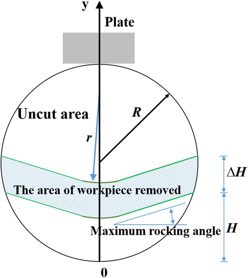
FIGURE 7. Wire saw area chart for a certain period of the circular wafer.
3 Simulation parameters and steps
Table 1 is the parameter table used for numerical simulation. In the single-factor numerical simulation experiments, the selection is made according to the data in the table, only the value of one parameter is changed, and the values of other parameters remain unchanged. Table 2 shows the parameters of the two kinds of workpieces used for numerical simulation, and the rectangular workpiece and the circular workpiece are selected respectively. The workpiece size is the cross-sectional shape size of the two selected workpieces. R is the cross-sectional radius of the circular workpiece, as shown in Figure 7. Both h and R are related to the final cutting position of the workpieces.
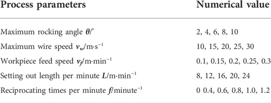
TABLE 1. Simulation process parameters.
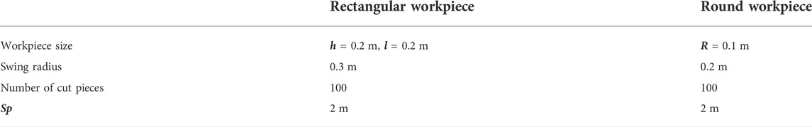
TABLE 2. Simulation workpiece parameters.
Considering the calculation time and calculation accuracy of the model, the accuracy of the model length is selected as 0.1 m. That is, the interval between matrix elements represents a length of 0.1 m.
The flowchart of the numerical simulation is shown in Figure 8. According to Figure 8, the steps of the numerical simulation are described as follows:
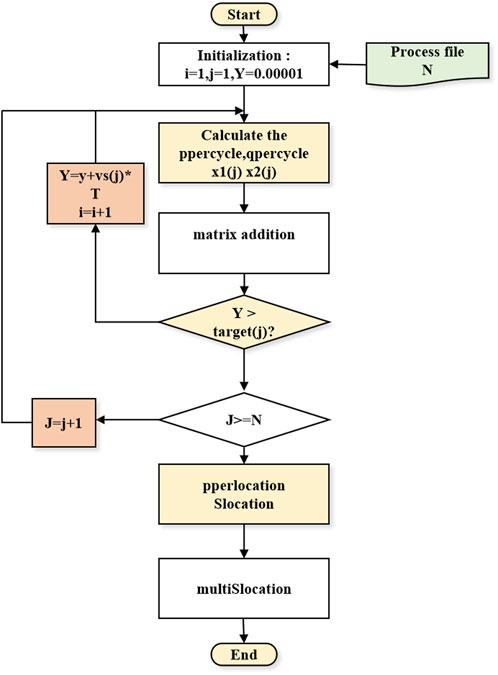
FIGURE 8. Numerical simulation flowchart of the wire saw wear model.
Step 1. Initialize the model, let I = 1, j = 1, and the cutting position y = 0.000001. Input the process file, extract the number of steps N, the target position target in each step, the maximum wire speed vw, the number of reciprocations f, the feed speed vf, the payout amount L, and the angle θ from the process file. j represents the number of steps in the current step, i represents the total number of cycles currently experienced, and y represents the processing position reached by the current wire saw.
Step 2. According to Eqs 1,2 and the simulation parameters of this step, calculate T,tf, td, tb, l, x1(j), x2(j). According to Section 2.2, calculate pcycle and qcycle.
Step 3. After calculating pcycle and qcycle in each cycle, according to the formulas in Section 2.2, the wear of each cycle is superimposed on the wire saw.
Step 4. Judgment y > target, if the condition is not established, proceed to the next cycle of processing, calculate the pcycle of the cycle, and perform matrix superposition according to Section 2.2.If the condition is established, it means that the wire saw has exceeded the processing area and should be stopped. At this time, it is necessary to use j ≥ N to judge whether there is the next process. If the condition of j ≥ N does not hold, there is the next process, the processing of the next process should be carried out, and the parameters corresponding to the next process are substituted into Step 2. For calculation. If the j ≥ N condition is established, it means that there is no next process, and the processing should be quit.
Step 5. After superimposing the wire saw wear of all cycles calculate the wire saw wear Slocation and plocation for cutting a single wafer.
Step 6. According to Section 2.3, the model of the wire saw for cutting the single piece is established. According to the number of workpieces to be cut, the superimposed matrix is calculated to obtain the wire saw wear model for cutting multiple wafers multiSlocation.
4 Numerical simulation results and discussion
4.1 Numerical simulation of rectangular workpiece
Only the line speed changes, it will not affect the change of the sawing area per cycle, nor the time length of the cycle. The change will only affect the values of tb and tf in the cycle, and according to Eq. (1), the speed becomes larger, and the (tf + tb) in Eq. (1) becomes smaller, thereby reducing the effect of speed change on the wear of the wire saw.
The feed speed of the workpiece and the length of the wire saw had an obvious impact on the maximum wear of the wire saw, and the maximum rocking angle, wire speed, and reciprocating times have no obvious effect on the maximum wear of the wire saw. The wire saw wear curve of a rectangular workpiece has a stable interval at the middle position, and it presents a changing state at the beginning and end of the curve. Changes in setting out length per minute and workpiece feed speed will lead to increased wire usage during processing. When the length of the wire involved in processing increases, the total volume of workpiece removed does not change, so the volume of workpiece removed evenly on each line will decrease, resulting in reduced wire saw wear as shown inFigure 9A,10C.
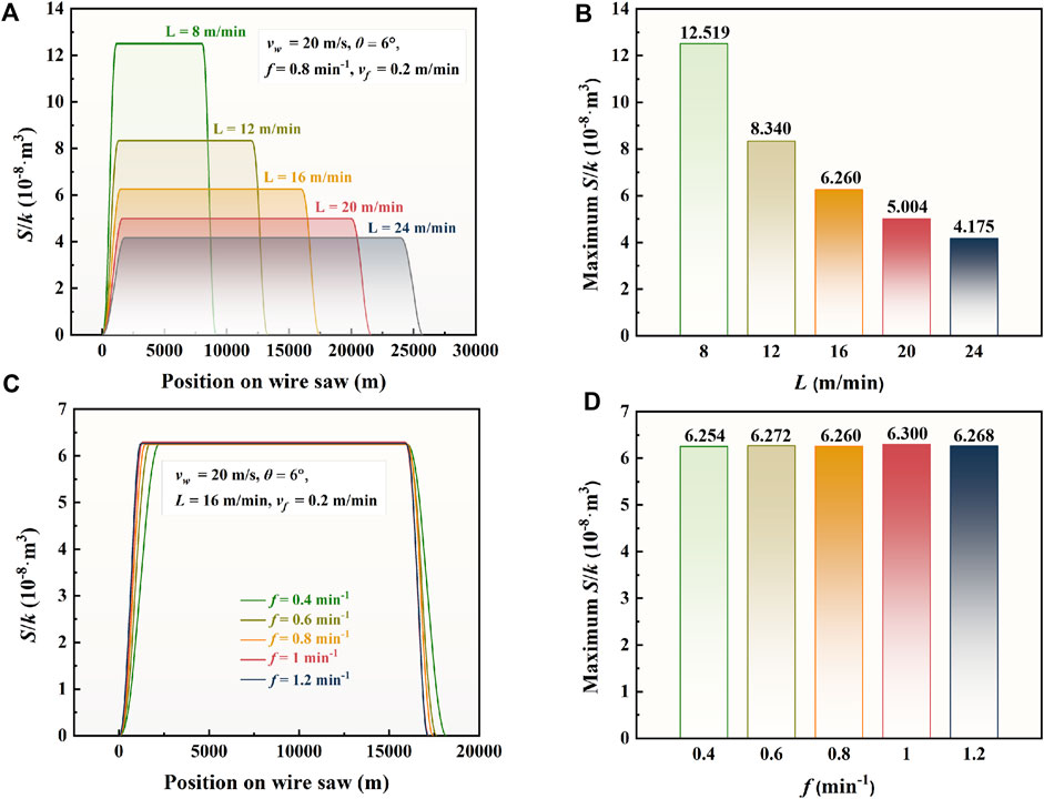
FIGURE 9. Variation of the wear amount of the wire saw on the rectangular workpiece and reciprocating frequencies. (A,B) illustrate the change in the setting out length will have an impact on the time difference between the take-up and pay-out. Under the condition that the wire feed length and speed remain unchanged, it directly affects the wire feed interval between two cycles, which in turn affects the number of superimpositions, thereby affecting the wear of the wire saw. (C,D) illustrate when the number of reciprocations changes, the time of the cycle will change, which will affect the time parameter of Eq. (1). The increase of tb and tf makes the value tend to decrease. At the same time, the difference between tb and tf will affect the wire feeding length of each cycle feeding stage, by increasing the wire feeding length and then increasing the number of superpositions, the influence of the number of reciprocations on the wear of the wire saw remains roughly unchanged.
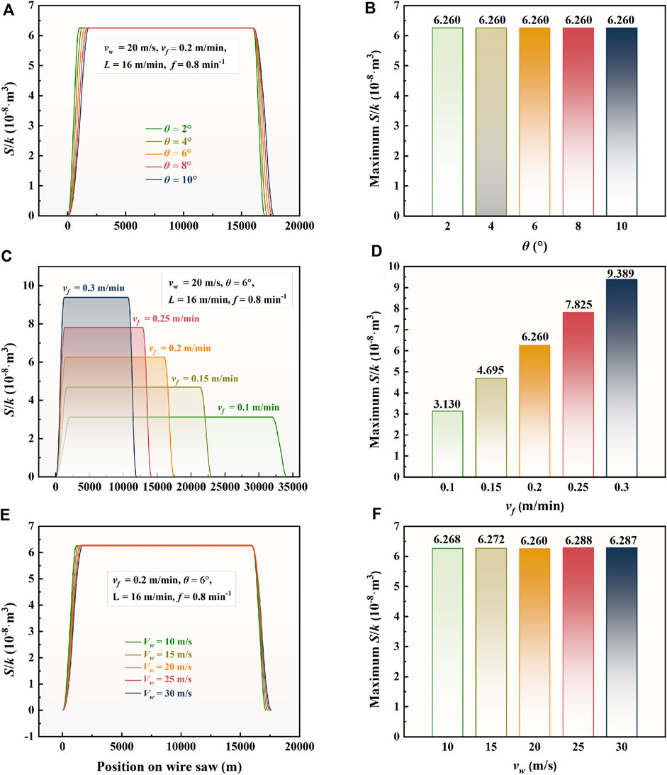
FIGURE 10. Variation of the wear amount of the wire saw on the rectangular workpiece under different maximum rocking angles, workpiece feed speeds and maximum wire speeds. Figure (A,B) illustrate the effect of the rocking angle on the maximum wear of the wire saw is not obvious, because the change of the angle is not obvious to the change of the sawing area in each cycle. Figure (C,D) illustrate the change of the workpiece feed speed has obvious changes to the maximum wear amount of the wire saw. This is because the change in the workpiece feed speed will cause the sawing area to follow the change in each cycle. Figure (E,F) illustrate the change of the wire speed has no obvious effect on the maximum wear amount of the wire saw.
4.2 Numerical simulation of circular workpieces
Wire saw wear curve for round workpieces varies throughout the phases. The biggest difference between a round workpiece and a rectangular workpiece is that the sawing area changes during the wire sawing process has a large unevenness.
During the sawing process, the contact length of the wire saw to the workpiece is the main reason for the unevenness. And this leads to a difference in the wear of the wire saw in the length when sawing round workpieces and rectangular workpieces. However, the situation of wire saw wear under different processing parameters is similar to that of the rectangular workpiece in Figures 11,12.
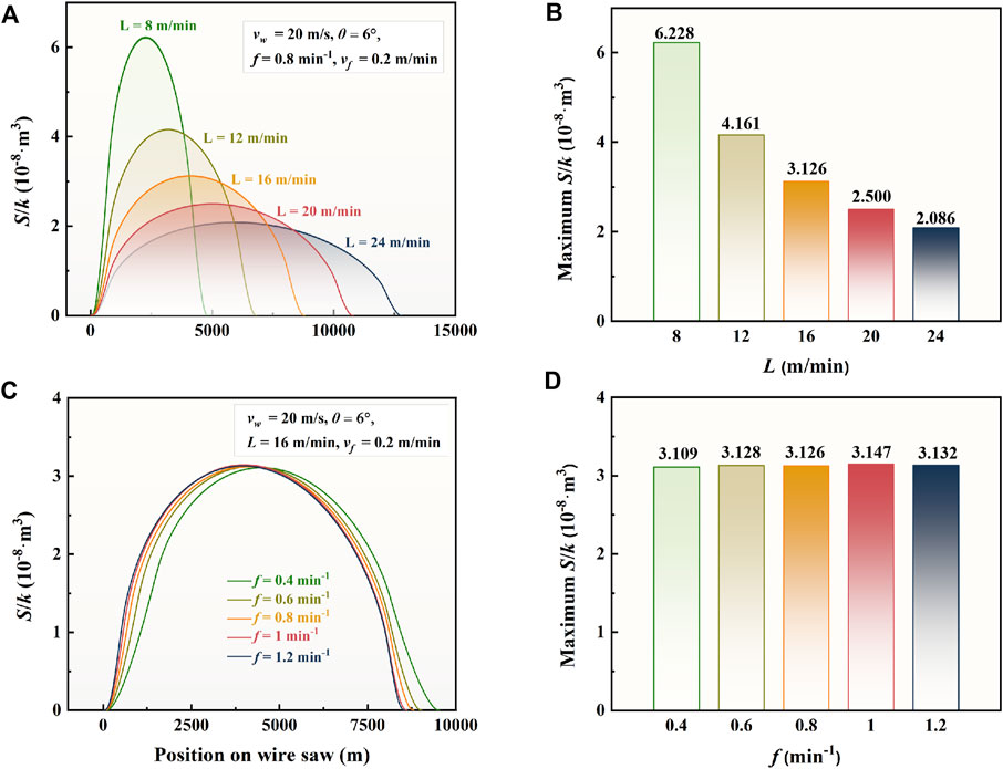
FIGURE 11. Variation of the wear amount of the wire saw for circular workpieces under different setting out lengths (A,B) and reciprocating frequencies (C,D).
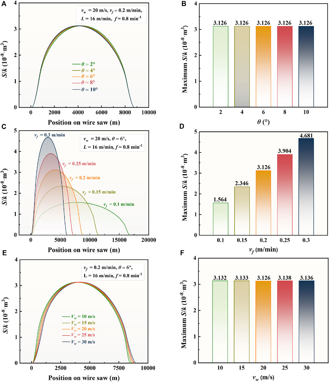
FIGURE 12. Variation of the wear amount of the wire saw for circular workpieces under different maximum rocking angles (A,B), workpiece feed speeds (C,D), and maximum wire speeds (E,F).
5 Conclusion
In this work, the wire saw wear model for multi-wire saw cutting of wafers was built, and the influence of cutting parameters on wear of the diamond wire saw was analyzed through multiple groups of single-factor simulations based on the wear model. From these simulation results and discussions, the conclusions can be summarized as:
1 When the relevant parameters are changed at the same rate, the feed speed of the workpiece and the length of the wire saw had an obvious effect on the maximum wear of the wire saw.
2 The maximum rocking angle, wire speed, and reciprocating times have no obvious effect on the maximum wear of the wire saw.
3 The shape of the workpiece has a significant effect on the wear of the diamond wire saw: the wear on the diamond wire saw was always uneven during cutting the circle ingot, while most of the wear on the diamond wire saw was even during cutting a rectangular ingot.
Data availability statement
The original contributions presented in the study are included in the article/supplementary material, further inquiries can be directed to the corresponding author.
Author contributions
ZY: investigation, data curation, visualization; HH: conceptualization, resources, and writing—review and editing; XL: writing—origianl draft, writing–review and editing.
Acknowledgments
The authors would like to acknowledge the financial supports from the Program for Innovative Research Team at University of the Ministry of Education of China (IRT_17R41), the Natural Science Foundation of Fujian Province (2022J05059), and the Scientific Research Funds of Huaqiao University (605-50Y21024).
Conflict of interest
The authors declare that the research was conducted in the absence of any commercial or financial relationships that could be construed as a potential conflict of interest.
Publisher’s note
All claims expressed in this article are solely those of the authors and do not necessarily represent those of their affiliated organizations, or those of the publisher, the editors, and the reviewers. Any product that may be evaluated in this article, or claim that may be made by its manufacturer, is not guaranteed or endorsed by the publisher.
References
Chen, K., Zha, J., Hu, F., Ye, X., Zou, S., Vähänissi, V., et al. (2019). MACE nano-texture process applicable for both single- and multi-crystalline diamond-wire sawn Si solar cells. Sol. Energy Mat. Sol. Cells 191, 1–8. doi:10.1016/J.SOLMAT.2018.10.015
Gao, Y., Ge, P., and Liu, T. (2016). Experiment study on electroplated diamond wire saw slicing single-crystal silicon. Mat. Sci. Semicond. process. 56, 106–114. doi:10.1016/j.mssp.2016.08.003
Huang, H., Zheng, S. L., and Xu, X. P. (2016). Theoretical research on contact length in the rocking motion wire saw. Adv. Mat. Res. 1136, 343–349. doi:10.4028/www.scientific.net/amr.1136.343
Kim, D., Kim, H., Lee, S., and Jeong, H. (2015). Effect of initial deflection of diamond wire on thickness variation of sapphire wafer in multi-wire saw. Int. J. Precis. Eng. Manuf. -Green. Tech. 2, 117–121. doi:10.1007/s40684-015-0015-x
Kim, H., Kim, D., Kim, C., and Jeong, H. (2013). Multi-wire sawing of sapphire crystals with reciprocating motion of electroplated diamond wires. CIRP Ann. 62, 335–338. doi:10.1016/j.cirp.2013.03.122
Knoblauch, R., Boing, D., Weingaertner, W. L., Wegener, K., Kuster, F., and Xavier, F. A. (2018). Investigation of the progressive wear of individual diamond grains in wire used to cut monocrystalline silicon. Wear 414–415, 50–58. doi:10.1016/j.wear.2018.07.025
Kumar, A., Kaminski, S., Melkote, S. N., and Arcona, C. (2016). Effect of wear of diamond wire on surface morphology, roughness and subsurface damage of silicon wafers. Wear 365, 163–168. doi:10.1016/j.wear.2016.07.009
Lee, S., Kim, H., Kim, D., and Park, C. (2016). Investigation on diamond wire break-in and its effects on cutting performance in multi-wire sawing. Int. J. Adv. Manuf. Technol. 87, 1–8. doi:10.1007/s00170-015-7984-3
Li, Z., Wang, M. J., Pan, X., and Ni, Y. M. (2015). Slicing parameters optimizing and experiments based on constant wire wear loss model in multi-wire saw. Int. J. Adv. Manuf. Technol. 81, 329–334. doi:10.1007/s00170-015-7229-5
Liu, Y., and Zhu, Z. (2022). Experimental investigation on diamond wire sawing of Si3N4 ceramics considering the evolution of wire cutting performance. Ceram. Int. 48, 17335–17342. doi:10.1016/j.ceramint.2022.02.296
Maeda, H., Takanabe, R., Takeda, A., Matsuda, S., and Kato, T. (2014). High-speed slicing of SiC ingot by high-speed multi-wire saw. Mat. Sci. Forum 778–780, 771–775. doi:10.4028/www.scientific.net/msf.778-780.771
Pala, U., Süssmaier, S., Kuster, F., and Wegener, K. (2018). Experimental investigation of tool wear in electroplated diamond wire sawing of silicon. Procedia CIRP 77, 371–374. doi:10.1016/j.procir.2018.09.038
Sekhar, H., Fukuda, T., Tanahashi, K., Takato, H., Ono, H., Sampei, Y., et al. (2020). Mechanical strength problem of thin silicon wafers (120 and 140 μm) cut with thinner diamond wires (Si kerf 120 → 100 μm) for photovoltaic use. Mat. Sci. Semicond. process. 119, 105209. doi:10.1016/j.mssp.2020.105209
Wang, P., Ge, P., Gao, Y., and Bi, W. (2017). Prediction of sawing force for single-crystal silicon carbide with fixed abrasive diamond wire saw. Mat. Sci. Semicond. process. 63, 25–32. doi:10.1016/j.mssp.2017.01.014
Yin, Y., Gao, Y., and Yang, C. (2021). Sawing characteristics of diamond wire cutting sapphire crystal based on tool life cycle. Ceram. Int. 47, 26627–26634. doi:10.1016/j.ceramint.2021.06.070
Keywords: multi-wire cutting, wire saw, wear, cutting parameters, numerical simulation
Citation: Yang Z, Huang H and Liao X (2022) Influence of cutting parameters on wear of diamond wire during multi-wire rocking sawing with reciprocating motion. Front. Mech. Eng 8:978714. doi: 10.3389/fmech.2022.978714
Received: 26 June 2022; Accepted: 21 July 2022;
Published: 30 August 2022.
Edited by:
Zhigang Dong, Dalian University of Technology, ChinaCopyright © 2022 Yang, Huang and Liao. This is an open-access article distributed under the terms of the Creative Commons Attribution License (CC BY). The use, distribution or reproduction in other forums is permitted, provided the original author(s) and the copyright owner(s) are credited and that the original publication in this journal is cited, in accordance with accepted academic practice. No use, distribution or reproduction is permitted which does not comply with these terms.
*Correspondence: Xinjiang Liao, eGluamlhbmdAaHF1LmVkdS5jbg==