 Mohan Kulkarni
 Sunil Dingare1
- 1MIT Art, Design and Technology University, Pune, India
- 2Department of Mechanical Engineering, Zeal College of Engineering, Pune, India
In this paper, the design and development of a solar cycloidal concentrating system along with utilization of the tapered receiver is presented. For the determination of the performance of the system, theoretical analysis was carried out. The novel concept of utilizing a tapered receiver for a solar cycloidal concentrating system is an innovative approach for this research. After the determination of various parameters for this system, a patent was filed and published under the patent No. 202021028009A on 31 July 2020. For the comparative study purpose, the author has taken three receivers with a constant concentration ratio and different diameters such as .038 m, .031 m, and .025 m. Theoretical evaluation of the system is estimated using modes of heat transfers and using the relation of energy balance. Various correlations are determined for an analytical evaluation purpose. By using graphical collation of all the results for all the three receivers, the author has proposed to use a tapered receiver with the variable CR. CR denotes the concentration ratio. A concentration ratio is defined as the ratio of the area of an aperture to the area of a receiver. In this research, a variable concentration ratio (CR) is used. The receiver used has a diameter which reduces from the inlet to the outlet, and hence, the intercept factor decreases and the concentration ratio increases, leading to an enhancement in efficiency.
1 Introduction
In order to utilize the available solar energy appropriately, it is essential to know the various phenomena occurring during the heat transfer in a solar heating system. There exists a need to know and control the various heat losses that happen in the system. The loss may result due to convection and radiation from the system. In addition to this, the losses due to reflection, absorption, and emission and the intercept factor need to be accounted. The existing line concentrators have a constant concentration ratio, which exhibits lower efficiency with a higher temperature difference between the initial (inlet) temperature and final temperature (outlet) of the fluid. As the area of the receiver surface gets minimized, the loss of energy will also get reduced. Hence, the author of this paper has proposed to use the tapered receiver to minimize thermal and heat losses, thereby increasing the system efficiency. In this paper, the author elaborates the details of theoretical estimation carried out for predicting the system performance. In this study, details of the development of the experimental set up and its design are discussed. The important point of the perspective of obtaining improved efficiency is to locate the receivers with respect to the concentrator, orientation of the system, and optical properties of the concentrator. For the development of the experimental setup, absorptivity, reflectivity, and the intercept factor are taken into consideration. All these factors are taken into account while developing the set up. The important aspect is the design of the tapered receiver, which is most critical in designing and manufacturing. In this paper, the author has described in detail the design, manufacturing of the solar system, and receiver assembly along with theoretical evaluation of system performance.
1.1 Literature review
Firdaus Muhammad (2011) presented a review on the solar concentrator where it is stated that apart from other designs, there is still a huge scope in the development of the design of the concentrator. Vasquez Padilla et al. (2011) conducted a research study using one-dimensional heat transfer analysis of a parabolic trough collector. To avoid heat losses, the receiver is covered using a transparent cover in this research. XianlongMeng et al. (2016) proposed a new model called the crossed compound parabolic concentrator (CCPC). It is determined that throughout the day, CCPC gives higher efficiency. Horta and Osorio (2014) carried out research where simulation was conducted for concentrators instead of using the experimental procedure. Lof et al. (2015) attempted for optimization of the collector design where the research carried out related to the concentrator area and receiver area. The flat receiver is used in this research, where the shadow effect was neglected. Beucherie (2015) and Mahdib and Bellel (2014) presented the development of a spherical solar collector with a cylindrical receiver. The intercept factor increases as the diameter of the receiver increases, but the efficiency decreases; hence, there is a need to focus on the increase in the concentration ratio. Caron and Roger (2015) proposed the model which can be used to design the receiver with heat transfer characteristics. MenWirz men wirz matthew roselle AldoSsteinfeldSteinfeld (2012) studied the effect of the system design on the average annual performance of the solar system and mentioned that if the receiver diameter increases, the system efficiency decreases. Lupfert a et al. (2004) mentioned in their research that the position of the receiver with respect to the focal line of the concentrator influences the intercept factor. After studying all this research articles, the author has found a research gap and a scope for the research based on which the proposed system is presented.
1.2 System constructional details
Figure 1 shows the layout of the experimental setup used.
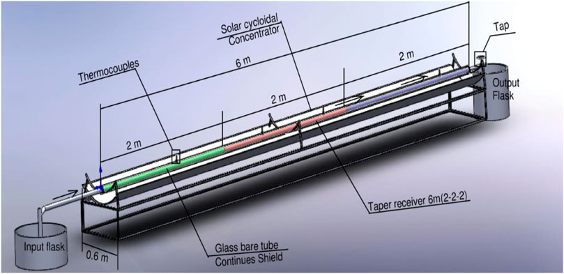
FIGURE 1. Setup of the solar cycloidal concentrator with a tapered receiver.
In this current framework, the fixed concentrating system and a movable receiver are used. The concentrating system is fixed in the E–W direction, and the trough surface is facing toward 18.50 south (Pune latitude). The trough is fixed in such a way that the sun beams lie on the outside of the framework. The reflector reflects the solar rays toward the receiver. The receiver is fixed in such a way that it can move along a trough with respect to the focal line. The general design of the framework consists of the fixed cycloidal concentrator with a portable tightened collector which can offer a required fixation proportion. Another important aspect is to collect maximum flux distribution from the cycloidal trough. The receiver is fixed in such a way that it collects the maximum flux along a focal line. Water is used as the working fluid. The working fluid travelled from the inlet end to the outlet end. Control valves at the inlet and outlet are used to control the flow of the working fluid. By using a thermometer, the temperature is measured at various points. A sun meter is used for measuring the energy received from solar rays. When selecting the rim angle, it is important to consider the position of the sun. The position of the sun for 18.5° latitude is shown in Figure 2. PT 100-type thermocouples are fixed at a specific location to measure the temperature of the working fluid, as shown in Figure 3; Table 1 shows the nomenclature used in the manuscript.
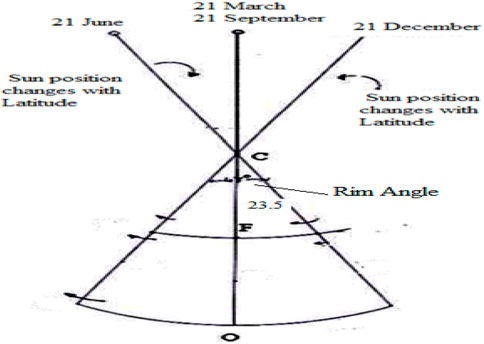
FIGURE 2. Path of the receiver showing a rim angle.
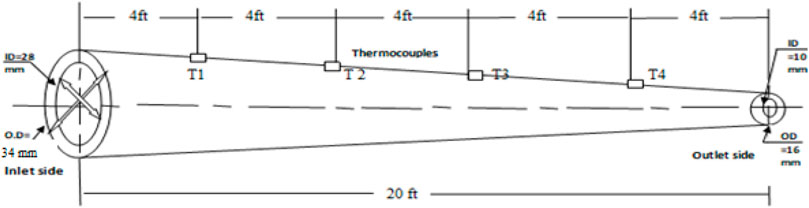
FIGURE 3. Receiver with a variable concentration ratio.
TABLE 1. Nomenclature.
Manufacturing specifications of the solar cycloidal concentrator are as follows:
• Incident beam radiation (Ib): 600 w/m2
• Reflectivity of the reflector surface (ρ): 0.95
• Absorptivity of the receiver (α): 0.8
• Emissivity of the receiver (Ε): 0.1
• Specific heat for water (Cp): 4.182 kJ/kg/°C
1.3 Selection of a geometrical parameter for the concentrator
The performance of the system gets affected by the geometry of the concentrator system like its aperture, length, rim angle, and radius of the concentrator. The aperture is the plane opening of the concentrator through which solar radiation passes. For the present cycloidal concentrating system, it is characterized by the width of the concentrator. The current experimental setup has a 6-m cycloidal trough with a reflecting sheet to reflect the solar rays, and the width of the concentrator is 0.6 m. If the radius of the concentrator is increased, the focal line moves up, and the tracking and cleaning of the receiver may be difficult. Also, the concentrator geometry affects the economics of the system. Considering these two major aspects, the various geometrical parameters for the concentrator are selected. In the present case, it is important to have the cycloidal line concentrator rather than the conventional parabolic line concentrator. The parabolic line concentrator has manufacturing challenges and is costlier; whereas, the cycloidal line concentrator is comparatively easy to manufacture economically without losing the performance.
1.4 Aperture area
It represents the effective area through which the solar insolation enters the concentrator. In the present case, the aperture area is taken as 3.6 m2 as the total length of the trough is 6 m, and the width of the concentrator is .6 m. Hence, the area of the aperture becomes 3.6 m2.
1.5 Selection of the rim angle
The rim angle is defined as the angle between the lines, (a) the line joining the sun’s position and the center of the reflector, and (b) the extreme end of the reflector and the center of the circle. The change in the angle of the rim causes variation in the distribution of the flux. Due to variation, an enlarged focus is obtained. In the proposed research, the East–West concentrating system is used; a 470 sun movement from north–south is noted, and a 23.50 angle is selected. Hence, a 470 arc is obtained. The sun’s movement is proportional to the latitude. It changes as the latitude changes. The position of the sun for the 18.5° latitude is shown in Figure 2.
Diurnally, the sun moves at a constant velocity of 15° per hour from east to west. This is an important factor while using a north–south-oriented cycloidal reflector. The end loss is the effect of oblique rays getting reflected and not being collected by the receiver. The non-normal incident rays on reflection are translated down the receiver and cannot be collected by the same. During the year, the sun goes through a straightforward consonant movement also termed as harmonic motion through an angle of 46.90 (around 470), in the north to south direction. This movement is a significant basis while utilizing the east–west-arranged concentrator.
1.6 Length of the trough
The three receiver tubes with a constant diameter which are used for comparative analysis are having the length of 6 m, which is the standard length of tubes available in the market. In the present case, the author of this paper has selected the length of the trough as 6 m as the length of the receiver is 6 m; hence, the trough length is also selected as the same. The aperture area is the product of the aperture and the length of the trough, which is equal to 3.6 m2.
1.7 Selection of the optical parameter for the concentrator
In the simplest form, the efficiency is expressed as follows:
As mentioned in aforementioned expression, the optical efficiency will change along with reflectivity and absorptivity as they are proportional with each other. Here, .95 reflectivity is taken for the present case.
1.8 Manufacturing of the cycloidal trough
The critical and important part of the system is manufacturing of the trough as the manufacturing inaccuracies may lead to deterioration of the system performance. It requires a stable structure of the trough so that its position remains unchanged even under high speed wind and environmental effects. Thus, the base frame is made heavy enough from a mild steel welded structure. In order to ensure that the reflector surface remains circular, due care is taken during manufacturing. The cycloidal arc of the included angle 47° is cut out of mild steel by laser cutting operation and is welded upon the base frame in required orientation. The spacing between these supporting arc structures ensures that the reflector does not bend and may not lead to sagging along the length. Over these, circular supports such as a backing (support) surface made of a 1.5-mm thick GI sheet is mounted by a spot weld. The actual reflecting surface is made up of Alanod–MIRO® 2 high specular manufactured by Alanod, Germany. As per the manufacturer’s specification, the reflectivity of the surface is .95. This sheet is pasted over the GI sheet which ensures that the used Alanod foil does not bend or wrap. When pasting the sheet, due care is taken to avoid wrinkles.
2 Tapered receiver assembly
The shape of the receiver is prepared as the tapered receiver as it compensates the loss of solar radiation due to changes in the position of the sun. The receiver used is bare and does not have any covering; however, it is coated with a black coating. The crucial parameter in this regard is the coating over the receiver as it plays an important role in the conversion of photon energy into thermal energy. It must provide high solar absorptivity and low thermal emissivity so as to have a good photo-thermal conversion of the operating temperatures. Considering cost viability, the enamel-based coating for the receiver was selected to manufacture a cost lower than the other solutions available on the market.
Manufacturing specifications of the tapered receiver assembly are as follows:
• Inlet end outer diameter: 34 mm
• Inlet end inner diameter: 28 mm
• Outlet end outer diameter: 16 mm
• Outlet end inner diameter: 10 mm
• Thickness: 6 mm
• Material: mild steel
• Thermocouple used: PT100
• Position of the thermocouple: After every 4 ft from the inlet, length: 6 m
During the manufacturing of the receiver, various operations like cutting of the rod, turning, arc welding, thermocouple fitting as per the design, and fitment of nozzles at the end of receivers are performed. The entire 20-feet rod is cut into a total of 20 pieces having a length of 1 foot each, and manufacturing was performed using CNC and machining work. The detailed design of the tapered receiver, along with the mounting of thermocouples, is as shown in Figure 3. The detailed design of each of the 20 pieces for manufacturing of the tapered rod is as shown in Figure 4. The author has already received copyrights for this design from the Government of India, as shown in Figures 3, 4.
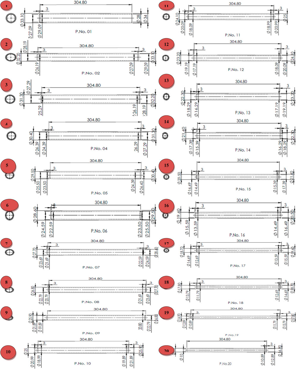
FIGURE 4. Detailed design of the 20 pieces of the receiver.
The actual image of the experimental setup is shown in Figure 5.
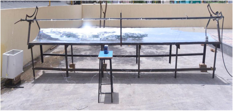
FIGURE 5. Actual image of the experimental setup with a tapered receiver.
3 Theoretical estimation
3.1 Heat loss minimization by adopting the variable concentration ratio
The ratio of solar radiation entering the collector to the solar radiation received by the receiver is termed as the concentration ratio and is expressed as follows:
Flux distributed across the area indicates intensity; hence, in the commercial sector, increase in the heat during its transfer creates problems. In an idle situation, the amount of energy intercepted by the aperture and received by the receiver is the same. Hence, Eq. 2 becomes as the following equation:
The first approach, i.e., increasing the area of the aperture, demands to have a large-size concentrator, which adds to the cost of the system and the space requirement. Thus, the second approach, i.e., reducing the size of the receiver, is more appropriate. However, with the constant CR, the efficiency of the system is found to be less. Thus, in order to reduce the losses, utilization of a tapered receiver is recommended. This approach to obtain the variable concentration by varying the receiver diameter is schematically shown in Figure 3. With this arrangement, the surface area of the receiver from the initial portion of the receiver to the successive end portion of receiver keeps on decreasing, leading to decrease in the loss of convention and loss of radiation. It is to be further noted that at a higher temperature, the heat loss from the surface is high; however, in the present system, having a tapered tube despite the increased temperature of water flowing in the tube, the loss of heat is reduced due to reduction in the diameter of the receiver; this helps enhance the system efficiency.
3.2 Evaluation of the intercept factor
Another important factor which is very important during performance evaluation is the shape factor, which is also called the intercept factor. It is defined as the ratio of the total energy reflected by the concentrator to the total energy absorbed by the receiver. The intercept factor can be estimated by the method discussed in this study. The flux distribution is assumed to be the function of the position in the plane of focus (which is considered as cylindrical in the present case), as shown in Figure 7. Distribution of the flux is related to its location from the center line such as the following expression:
Figures 6, 7 show complete dissemination of the sun-based energy on the cycloidal concentrator and address the impression of the radiations or energy per unit length reflected along a line of core interest. The capture attempt of the receiver for the transmitted beam to reach from + w to −w is displayed in Figure 6; the concealed piece addresses the interference of the receiver and is evaluated as the following expression:
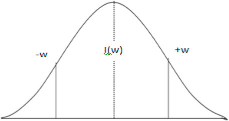
FIGURE 6. Flux distribution.
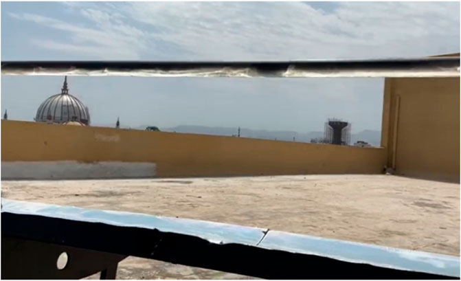
FIGURE 7. Actual image of solar flux distribution on the receiver tube.
Considering the infinite range of the tapered receiver diameter,
Hence, the intercept factor is expressed as follows:
When the intercept factor is high, the system gets the desired output. In general, an optimum receiver size results in the maximum energy gain by minimizing the sum of the optical and thermal loss. In the present system, varying the diameter of the receiver and the concentrator resulted into increasing the concentration ratio and decreasing the intercept factor along the length of the receiver from the inlet to the outlet. Hence, the desirable characteristics are obtained by reducing the thermal losses and enhancing the system efficiency. The intercept factor is evaluated by using the data from Lof et al. (2015).
3.3 Analytical estimation
The analytical evaluation of the solar cycloidal concentrator system is carried out by using different equations. Considering the unvarying condition, evaluation of the solar cycloidal concentrator is elaborated by the energy-balancing condition. Figure 8 represents this condition, which indicates utilization of sun beams on the trough and their usage in terms of thermal gain and various losses.
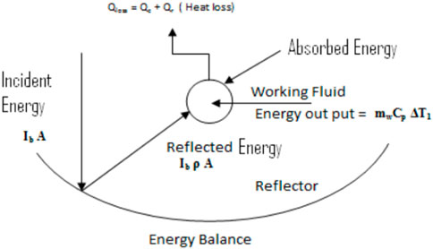
FIGURE 8. Energy balance of the cycloidal concentrator.
The relationship of the factor of the intercept with the receiver diameter is shown in Table 2.
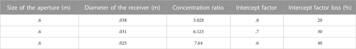
TABLE 2. Relationship between intercept factor and concentration ratio.
Distribution of incident energy along with the focal line was measured by the flux meter, and the factor of the intercept for the receiver tubes is evaluated:
The product of incident solar rays over the concentrator area and the concentrator reflectiveness will give the total energy reflected by the cycloidal concentrator.
Incident solar rays can be measured by using the sun meter. Expression (9) can be written as follows:
Figure 9 shows that solar rays are incident on the cycloidal concentrator. These solar rays are reflected by the concentrator. This reflected flux has been distributed on the receiver. This phenomenon is nothing but the intercept factor. Heat losses are minimized as the diameter of the receiver tube goes on decreasing.
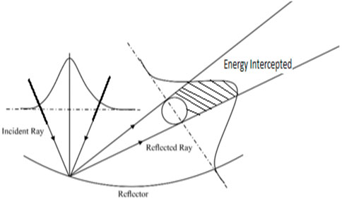
FIGURE 9. Incident beam reflection and distribution over the receiver (Caron and Roger, 2015).
The following expression describes the evaluation of performance using the energy-balancing condition:
Loss of heat due to convection Qc from the receiver tube is expressed as follows:
Radiation loss Qr is expressed as follows:
For the estimation of the heat transfer coefficient hc, the Nusselt number is expressed as follows:
The convective heat transfer coefficient (hc) for the external surface of the receiver is estimated as follows:
The Grashof number for free convection is evaluated by the following expression:
The Rayleigh number (Ra) is expressed as follows:
With the usage of all aforementioned expressions for a tapered receiver, the convective loss and radiation loss are evaluated.
4 Results and discussion
The temperature gained by the working fluid depends on the receiver surface temperature; thus, the receiver temperature affects the system efficiency. The efficiency obtained from a system having a different concentration ratio is shown in the following figures: Figures 10, 11 and Figures 12, 13.
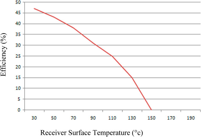
FIGURE 10. Efficiency vs. the receiver surface temperature for a .038-m receiver tube.
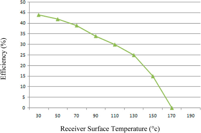
FIGURE 11. Efficiency vs. the receiver surface temperature for a .031-m receiver tube.
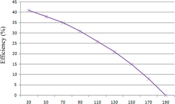
FIGURE 12. Efficiency vs. the receiver surface temperature for a .025-m receiver tube.

FIGURE 13. Graphical collation of receiver diameters.
It was found that for all the systems, the efficiency decreases with increase in the receiver surface temperature as it leads to higher radiative and convective loss. The fall of system efficiency is rapid for the system having a lower concentration ratio. However, as anticipated in the design of the system with a variable concentration ratio, the fall of efficiency was at a lower rate. Also, the obtained temperature of the working fluid at the outlet is comparatively high. The experimental result reveals the fact that the change in the concentration ratio for the system with a variable concentration ratio has a definite relation with respect to the receiver surface temperature. Considering the receiver temperature and the rate of fall of efficiency, the designed system with a variable concentration ratio has improved its performance results. The efficiency will be obtaining the highest results among all the considered systems with a uniform concentration ratio; also, the rate of fall of efficiency with a rise in the receiver surface temperature is low. Hence, the proposed design of the system with a variable concentration ratio system for a given concentrator of defined geometry is realized.
5 Conclusion
The research carried out by the author has put forth an innovative approach of using a solar concentrating system by adopting the variable concentration ratio.
• It is observed that for a receiver with a large diameter, maximum solar flux has been distributed over the surface of the receiver, leading to a maximum intercept of energy on its surface. However, as total loss including convective and radiation losses is also maximum, the temperature decreases and the efficiency reduces.
• For a receiver with a small diameter, minimum solar flux has been distributed over the surface of the receiver, leading to a minimum intercept of energy on its surface. However, as total loss including convective and radiation losses is also minimum, the temperature increases and the efficiency also increases.
• The trend shows that as the receiver diameter reduces, the ratio of the concentration increases, and the intercept factor decreases, as shown in Table 2.
• As the diameter of the receiver tube decreases, its surface temperature increases, which is proved after performing the comparative analysis and shown graphically, as shown in Figure 13. Also, due to a smaller diameter of the receiver tube, convective and radiation losses are also minimum. Due to this, the higher temperature difference obtained leads to improvement in the efficiency.
• These results are applicable and useful for deciding whether to use the solar cycloidal concentrating systems for temperature requirements for various industrial processes. These systems will replace traditional technologies of solar water heating systems as these systems are not economical and very critical in construction. The application of temperature requirements in the food industry for drying, washing, boiling, and sterilizing; in the beverage industry for washing, sterilizing, and pasteurizing; in the textile industry for bleaching, dying, and pressing; in the dairy industry for pasteurizing and drying; in the paper industry for the boiler and feed water; and for cooking. It will also be useful for all such applications where there is a need for hot water.
• Based on the proposed concept of the variable concentration ratio receiver, the system is analyzed theoretically. The author has thus proposed to use the variable concentration ratio that is of the tapered receiver for enhancing the efficiency. As in this case, as the diameter reduces from the inlet to the outlet, the concentration ratio increases, the intercept factor reduces, and efficiency increases.
Data availability statement
The original contributions presented in the study are included in the article/supplementary material; further inquiries can be directed to the corresponding author.
Author contributions
MK: conceptualization, methodology, and experimentation. SD: validation and resources. CK: supervision.
Conflict of interest
The authors declare that the research was conducted in the absence of any commercial or financial relationships that could be construed as a potential conflict of interest.
Publisher’s note
All claims expressed in this article are solely those of the authors and do not necessarily represent those of their affiliated organizations, or those of the publisher, the editors, and the reviewers. Any product that may be evaluated in this article, or claim that may be made by its manufacturer, is not guaranteed or endorsed by the publisher.
References
MenWirz men wirz matthew roselle Aldo, S., and Steinfeld, A. (2012). Three dimensional optical and thermal numerical model of solar tubular receivers in parabolic trough concentrators. J. Sol. energy Eng. ASME 134, 041012/1–9. doi:10.1115/ES2012-91154
Beucherie, P. (2015)., 3. 125–137. doi:10.1016/0378-7796(80)90028-0Selective absorbent surfaces for high temperature solar collector, Electr. power Syst. Res.
Caron, S., and Roger, M. (2015). Modeling, Simulation and Identification of heat loss mechanisms for parabolic trough receivers installed in concentrated solar power plants. Spain: German Aerospace Center (Dlr) Institute For Solar Research, 1–6. doi:10.1016/j.ifacol.2015.05.058
Firdaus Muhammad, S. (2011). A review on solar concentrator. Int. J. Appl. Sci. (IJAS) 1 (1), 1–15. doi:10.1016/j.rser.2018.03.039
Horta, P., and Osorio, T. (2014). Optical characterization parameters for line focusing solar concentrators: Measurement procedures and extended simulation results. Elsevier Energy Procedia 49, 98–108. doi:10.1016/j.egypro.2014.03.011
Lof, G. O., Fester, D. A., and Duffie, J. A. (2015). Energy balances on a parabolic cylinder solar collector. ASME 84, 24–32. doi:10.1115/1.3673371
Lupfert a, E., Herrmann, U. b., Price c, H., Zarza d, E., and Kistner, R. (2004). “Towards standard performance analysis for parabolic trough collector fields,” in Proceddings of the Solar Paces Conference, Mexico, Oaxaca Luepfert, October 2004, 22–27.
mahdib, K., and Bellel, N. (2014). Development of a spherical solar collector with a cylindrical receiver. EnergyProcedia 52, 438–448. doi:10.1016/j.egypro.2014.07.096
Vasquez Padilla, R., Demirkaya, G., Goswami, D. Y., Stefanakos, E., and Rahman, M. M. (2011). Heat transfer analysis of parabolic trough solar receiver. Appl. Energy 88, 5097–5110. doi:10.1016/j.apenergy.2011.07.012
XianlongMeng, N. S., Knox, A. R., Andrea, M., JonathanSiviter, P. M., AliAsraf, A. S., Llin, L. F., et al. (2016). A novel absorptive/reflective solar concentrator for heat and electricity generation; an optical and thermal analysis. Energy Convers. Manag. 114, 142–153. doi:10.1016/j.enconman.2016.02.011
Keywords: tapered receiver, solar cycloidal concentrator, theoretical evaluation, efficiency, performance
Citation: Kulkarni M, Dingare S and Kulkarni C (2023) Design and development of the solar cycloidal thermal concentrator and tapered receiver assembly along with theoretical evaluation of system performance. Front. Mech. Eng 8:998630. doi: 10.3389/fmech.2022.998630
Received: 20 July 2022; Accepted: 29 December 2022;
Published: 12 January 2023.
Edited by:
Tapano Kumar Hotta, VIT University, IndiaReviewed by:
Radu Iacob Cotetiu, Technical University of Cluj-Napoca, RomaniaIvan Giorgio, University of L’Aquila, Italy
Copyright © 2023 Kulkarni, Dingare and Kulkarni. This is an open-access article distributed under the terms of the Creative Commons Attribution License (CC BY). The use, distribution or reproduction in other forums is permitted, provided the original author(s) and the copyright owner(s) are credited and that the original publication in this journal is cited, in accordance with accepted academic practice. No use, distribution or reproduction is permitted which does not comply with these terms.
*Correspondence: Mohan Kulkarni, bW9oYW4ua3Vsa2FybmlAbWl0dW5pdmVyc2l0eS5lZHUuaW4=