 Ziqiang Ren
 Jiawang Chen
 Jin Guo
 Bijin Liu1
- 1Hainan Institute, Zhejiang University, Sanya, China
- 2Ocean College, Zhejiang University, Zhoushan, China
The seabed Cone Penetration Test (CPT) system is a common method for investigating offshore soil. This paper focuses on a new subsea CPT method for assessing physical and mechanical properties of marine sediments. The new method enables automatic docking and dismantling of the probe rods underwater. The constant-rate penetration mechanism is the basis and core component of the seabed CPT, allowing the probe rod and cone to penetrate the seafloor sediment. Double hydraulic cylinders are used to meet the high penetration force requirements. To maintain a constant penetration rate of 20 ± 5 mm/s, the model identification of the electro-hydraulic servo system is performed using Simcenter AMESim and MATLAB software, and the relevant transfer function is obtained using the PID method. Based on this transfer function, the sliding mode variable structure controller of the electro-hydraulic servo system is designed to regulate the constant penetration rate of the hydraulic cylinder against varying penetration resistance. In-situ measurements were operated using the new seabed CPT rig in Zhoushan Island. The simulation and testing results confirm that the sliding mode variable structure controller is suitable for controlling the system during actual operation.
1 Introduction
Submarine sediments are the main research objects of marine engineering geology, which are characterized by high plasticity, high water content, looseness, and high sensitivity (McKay and Pedersen, 2008). The existing sampling means, such as gravity sampling, vibration sampling, and drilling sampling, and the stress–strain state of the sediment soil will change to some extent during the sampling process, thus affecting the accuracy of the test results (Low et al., 2011). Therefore, the technical method of in situ testing can facilitate the accuracy of the investigation of soil properties for marine sediments. The seabed cone penetration test (CPT) is a simple, economical, and efficient in situ measurement method for seabed soils with reliable measurement data, which has a broad application prospect in the offshore engineering survey and geohazard research (Wang, 1986; Tom, 2012). The CPT has played an important role in the assessment of offshore soil properties over the past decades (Lunne et al., 2002; Lunne, 2010). Undertaking seabed CPT investigations has always been a challenging task, especially in the deep-sea environment. Currently, most seabed CPT equipment used for large depth surveys adopts a straight rigid probe rod with a support frame that is several times larger than its height, resulting in inconvenience during offshore operations (Seidman and Lim, 2011; Sheng et al., 2014). The flexible probe rod method is only suitable for shallow surfaces with softer strata as the thruster assembly provides all the means of connecting the cone rod to the motor/gearbox assembly and straightening the rod as it is pushed out (Meunier et al., 2004; Jorat et al., 2014). To overcome these limitations and increase the survey depth while improving efficiency, we propose a new seabed CPT system that utilizes an innovative probe rod mechanism capable of automatic docking and dismantling underwater, allowing for a more comprehensive investigation of the physical and mechanical properties of marine sediments.
This paper begins by providing a brief introduction to the structure and working principle of the seabed CPT. Subsequently, we present the constant-rate penetration mechanism, which forms the core of the seabed CPT system. To achieve a constant penetration rate of 20 ± 5 mm/s (ISSMGE, 1999; ASTM D, 2020), we first perform the model identification of the electro-hydraulic servo system using Simcenter Amesim and MATLAB software applications, and obtain the relevant transfer function through the proportion–integral–differential (PID) method. Based on the transfer function, we design a sliding-mode variable structure controller to regulate the constant penetration rate of the hydraulic cylinder even under changing penetration resistance. The simulation results demonstrate that the method is precise and easily operable. Finally, we perform in situ measurements with the new seabed CPT rig to determine the physical and mechanical properties of the sediment at Zhoushan Island, Zhejiang, China, at coordinates
2 Design of the seabed cone penetration test system
2.1 Structure and composition of the seabed CPT
As shown in Figure 1, the subsea CPT system studied in this paper has dimensions of 1,950 mm in width and 3,500 mm in height. It comprises an integral frame, a constant-rate penetration mechanism, a large-capacity storage mechanism, a transfer mechanism, an automatic docking and dismantling mechanism, counterweights, a ballast plate, a hydraulic drive system, and a control power supply system. The weight of the seabed CPT varies from 5 to 12 tons in air depending on the ballast plate’s weight, which can be added to the base frame to increase the system’s pushing capacity. Furthermore, the ballast plates lower the center of gravity, improving the system’s stability on the seabed. The automatic docking and dismantling mechanism is located at the top of the constant-rate penetration mechanism, while the transfer and storage mechanisms are fixed on either side of the constant-rate penetration mechanism. The overall installation places the constant-rate penetration mechanism at the center.
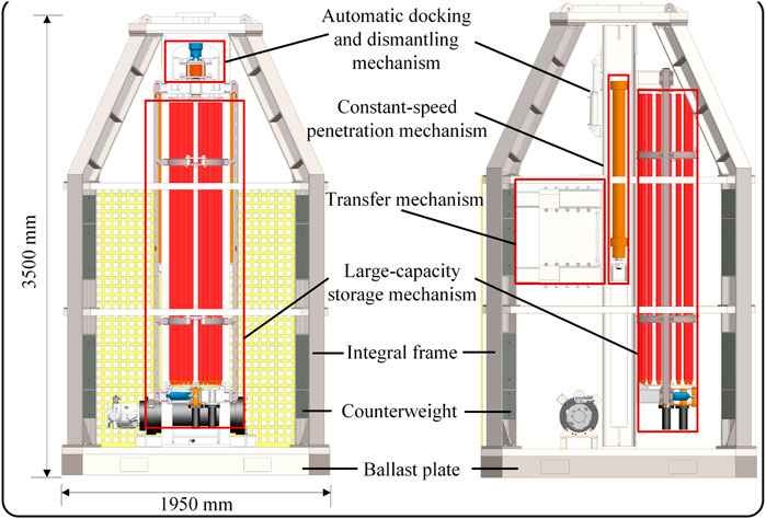
FIGURE 1. Schematic diagram of the overall structure.
2.2 Structure of the constant-rate penetration mechanism
Standard CPT data acquisition involves a constant penetration rate of around 20 ± 5 mm/s. To achieve this, a double-acting hydraulic cylinder system is utilized to drive the probe rod into the sediment with the dynamic position controller, ensuring a consistent penetration rate regardless of varying sediment resistance. The mechanism comprises a support column, two hydraulic cylinders, a clamping device, a speed sensor, a supporting frame, and a servo-hydraulic valve box, among others, as depicted in Figure 2. The clamping device secures the probe rod on the penetration hydraulic cylinder, which is then driven vertically, pushing the probe rod continuously into the seafloor. The speed sensor, comprising a support frame, fixed and movable rollers, a spring, and a speed encoder, measures the penetration rate and displacement and sends the data to the electro-hydraulic servo valve, which regulates the pressure and flow rate of the hydraulic lines to achieve a constant penetration rate. The system adopts a double-acting hydraulic cylinder driving mode to meet the need for the large penetration force, with ballast plates on the frame allowing for up to 100 KN of compressive forces to be transmitted from the hydraulic piston to the push rod. The clamping device employs hydraulic transmission, which passively increases the push–pull force (Figure 3).
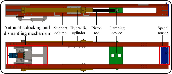
FIGURE 2. Constant-rate penetration mechanism.
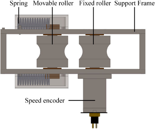
FIGURE 3. Speed sensor.
2.3 Design of the hydraulic system for the constant-rate penetration mechanism
Two common hydraulic transmission devices are pump-controlled and valve-controlled. In a pump-controlled hydraulic system, the actuator’s work is accomplished by adjusting the flow of the hydraulic pump. Despite its high efficiency, this method has limited control effectiveness. Open systems with valve-controlled hydraulic systems utilize proportional valves or servo valves to control the joystick. This approach features energy efficiency, low heat generation, and precise control (Ferrari et al., 2013; Ren et al., 2021). To ensure a good dynamic response performance, this paper uses a hybrid hydraulic system comprising both pump and valve controls. This approach combines the advantages of both methods. Using flow-adaptive hydraulic pumps maintain a consistent flow rate, meeting the hydraulic components’ needs, which reduces excess flow and hydraulic losses, resulting in increased system efficiency. A constant-pressure variable pump powers the hydraulic system, which not only provides a continuous supply of hydraulic oil at a constant pressure to the penetration system but also adjusts the output flow according to the workload’s required flow rate. Given the fact that the system of the seabed CPT uses two-way transmission through the cable and console in both directions, the hydraulic penetration system employs servo valves to precisely regulate the penetration rate.
The hydraulic schematic representation of the constant-rate penetration mechanism is shown in Figure 4, which is mainly composed of a hydraulic pump, deep-sea motor, electro-hydraulic proportional pressure-reducing valve, servo valve, hydraulic cylinders, probe rod, speed sensor, relief valve, and other hydraulic accessories. To achieve a precise penetration rate, the speed sensor continuously measures the actual penetration rate, and this is transmitted to the controller and compared with the target speed. The servo valve then adjusts the flow rate of the hydraulic lines using the feedback from the controller to regulate the rate deviation value.
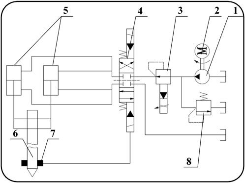
FIGURE 4. Hydraulic schematic diagram of the constant-rate penetration mechanism: 1) hydraulic pump, 2) deep sea motor, 3) electro-hydraulic proportional pressure-reducing valve, 4) servo valve, 5) hydraulic cylinders, 6) probe rod, 7) speed sensor, and 8) relief valve.
3 Model identification of the constant-rate penetration electro-hydraulic servo system based on Simcenter Amesim and MATLAB
According to theoretical derivations, the electro-hydraulic valve-controlled cylinder system is a third-order system consisting of an integral link and a second-order oscillation link, without considering the dynamic process of the servo valve (XieChenGuo, 2013; Bai et al., 2014). However, due to the non-linearity of the system, its parameters vary at different operating points. A unified theoretical formula exists for the parameters of linearized models for symmetrical valve-controlled asymmetric cylinders, but deriving any position of the valve-controlled asymmetric cylinder piston requires specific parameters, resulting in a complex and laborious process. Furthermore, simplifications and assumptions applied in the establishment of the linear model can reduce the accuracy of the results. In contrast, the method of linear analysis based on Simcenter Amesim can address these technical issues and enable the simulation analysis of the characteristics of valve-controlled asymmetric cylinder systems (Ding et al, 2015; Guo et al., 2017).
For the complexity and variability of the hydraulic cylinder system model, this paper proposes an identification method of the hydraulic servo system based on Simcenter Amesim and MATLAB. The basic process of model identification is organized as follows. First, according to the actual requirements, Simcenter Amesim software is used to establish the corresponding hydraulic simulation model, as shown in Figure 5, and simulation is carried out in the linear analysis mode. A constant-pressure variable pump is utilized to power the hydraulic system through the motor. The penetration velocity of the cylinder is regulated using a servo valve. Additionally, a displacement sensor is connected to the cylinder to measure its displacement and speed. To indicate resistance during penetration, a variable force is added to the end. The displacement and speed data from the sensor are compared with the preset values. Subsequently, the PID controller governs the displacement and speed of the cylinder. The system variable setting is presented in Table 1. From the data analysis conducted through Simcenter Amesim, the relationship between the desired or actual displacement and time is obtained during the working process, as shown in Figure 6. The simulation analysis results show that the actual displacement is close to the desired displacement, and the rate is close to the target penetration rate of 20 mm/s under variable load conditions.
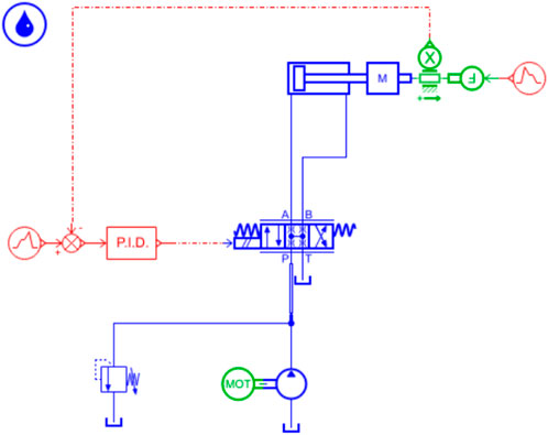
FIGURE 5. Hydraulic simulation model of the penetration mechanism.
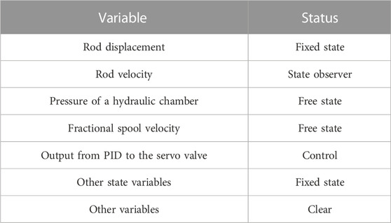
TABLE 1. System variable setting.
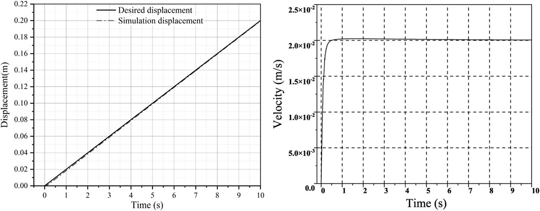
FIGURE 6. Relationship between the displacement and rate of rod and time.
Moreover, the corresponding script file is run through MATLAB to obtain the transfer function obtained from the system model identification. The Jacobi matrix function in Amesim is loaded by the ameloadj function in MATLAB.
In a matrix or a state space, the equation can be expressed as
where
Finally, the transfer function obtained from the system where model identification was used to establish a validation simulation model to verify the system identification method, as shown in Figure 7. The data analysis performed by Simcenter Amesim yielded the relationship between displacement and time during the working course, as shown in Figure 8. To more visually display the difference between the desired and actual displacement, Figure 9 presents the difference based on different simulation models. The displacement difference increases and then gradually decreases over time. The maximum difference in displacement was approximately 1.9 × 10⁻³ m based on the validation simulation model and approximately 1.7 × 10⁻³ m based on the hydraulic simulation model. The simulation analysis results indicate that the actual value is close to the target value, indicating the validity of the system identification method.
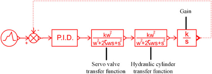
FIGURE 7. Validation simulation model.
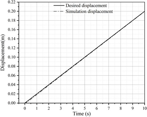
FIGURE 8. Relationship between displacement and time.
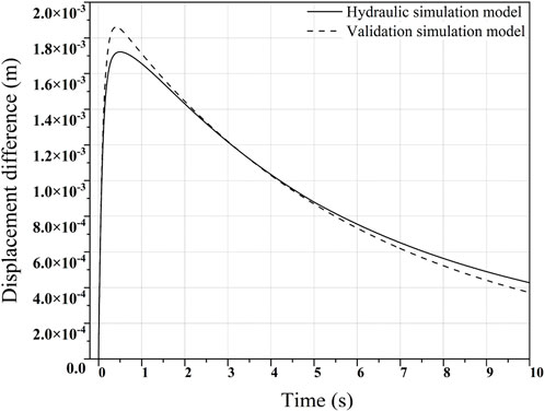
FIGURE 9. Displacement difference based on different simulation models.
4 Design of the sliding mode control for the constant-rate penetration electro-hydraulic servo system based on Simcenter Amesim and MATLAB
The electro-hydraulic servo system is a common type of an uncertain non-linear system, with the weakness of parameter variation and external disturbance. Sliding mode control (SMC) is a highly effective robust control strategy that has been widely utilized (Sa et al., 2022). Using the sliding mode control method is a highly effective control strategy for the electro-hydraulic servo system (Wang et al., 2019). Sliding mode control is known as the variable structure control, which is a unique form of non-linear control. Its non-linearity mainly stems from its flexible structure that can be tailored to different control methods (Cheng et al., 2020). The sliding mode structure can be modified in response to the system’s current state, such as the phase offset and its derivatives. Because the sliding mode can be designed without being influenced by object parameters and disturbances, it has several advantages, including fast response speed and insensitivity to parameter changes and disturbances, and does not require online identification of the system. Moreover, it is easy to implement physically (Thien and Kim, 2018; Haddad and Mirkin, 2020).
The fundamental principle of the sliding mode control is structured as follows. The switching plane is designed based on the desired dynamics of the system, and the system state gradually converges to this plane through control action. When the system state reaches the switching plane, the control action will prevent the system state from leaving the plane and ensure that the system state moves along the plane until it reaches the system’s origin (Zhao et al., 2016; Ngo et al., 2017).
The motion trajectory of the sliding mode control is mainly divided into two main aspects: 1) the stage of moving to the sliding mode plane from any initial state of the system; and 2) the stage when the system reaches the sliding mode plane and slowly stabilizes. Therefore, the design of the sliding mode controller, corresponding to the two phases of the system motion, can be divided into two parts, including the design of the sliding mode plane and the design of the control law.
4.1 Setting of the sliding mode plane
A transfer function is a mathematical representation of the relationship between the input and output of a linear, time-invariant system. The transfer function of a system is defined as the ratio of the output to the input in the frequency domain, assuming that the initial conditions are zero. In other words, it describes how a system responds to different frequencies of input signals. The transfer function is represented using the Laplace transform, which converts the time-domain signal into the complex frequency-domain representation. The equation can therefore be expressed as
where
The electro-hydraulic servo system simplifies it into a proportional link without considering the non-linear effects of the servo valve. Through model building and numerical analysis of the electro-hydraulic servo system, the transfer function of the servo-valve hydraulic cylinder system can be determined as
where
The transfer function of the identified model can thus be given as
The state space equation can be expressed as
The controlled object is a third-order system, and
The error vector of the defined system can therefore be expressed as
The state-space equation of the system model can be expressed as
Based on the state-space equation, the state error equation can therefore be expressed as
The sliding mode switching function can be expressed as
The differential equation of the sliding mode motion can be expressed as
For meeting the requirements of
The aforementioned equation determines the dynamic quality of the sliding mode; thus,
4.2 Design of the slide mode controller
The slide mode controller is essentially a way to change the control state by means of switching switches. It is fully robust as a discontinuous control, which is not disturbed by object parameters and external disturbances in the sliding mode region. The slide mode controller can thus be expressed as
where
The derivation of the differential equation can be expressed as
The equivalent control is, therefore, given as
The exponential approximation law is applied to switching control. It can be determined as
If
In summary, the slide mode controller can be expressed as
4.3 Dynamic simulation of the penetration mechanism
Due to its powerful computing capabilities, MATLAB/Simulink has widely been used in various fields. By combining simulation technology with the exceptional fluid simulation capabilities of Simcenter Amesim and the powerful digital processing capabilities of MATLAB/Simulink, optimal simulations can be achieved (Kıyan et al., 2013; Wang et al., 2017). Simcenter Amesim software was utilized to establish the required hydraulic simulation model, and an interface block was created, as shown in Figure 10, to carry out the simulation in the linear analysis mode, based on specific requirements. Figure 11 shows the model of the control system.
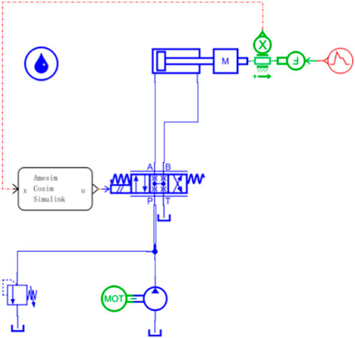
FIGURE 10. Hydraulic co-simulation mode of the penetration mechanism.
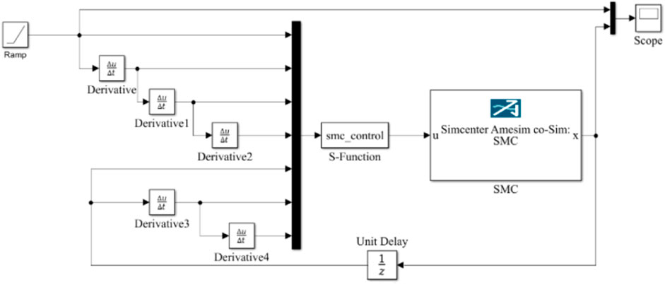
FIGURE 11. Model of the control system.
The relationship between the displacement and rate of the hydraulic cylinder rod over time during operation is obtained through data analysis performed by Simcenter Amesim and MATLAB/Simulink, as illustrated in Figure 12. For better visualization, the displacement difference based on different simulation models is presented in Figure 13. The displacement difference increases and then gradually decreases over time. The maximum displacement difference based on the co-simulation model is approximately 2.8 × 10⁻⁴ m. Furthermore, the displacement difference based on the hydraulic simulation model during the entire simulation process is much larger.
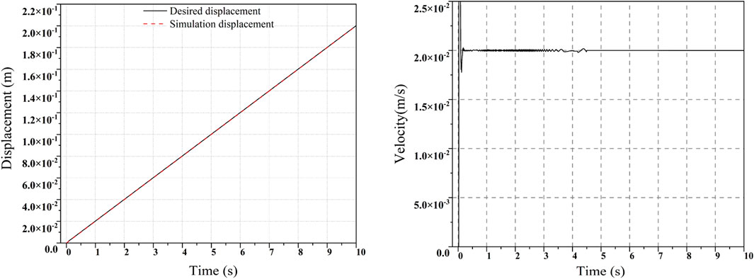
FIGURE 12. Relationship between displacement/rate and time.
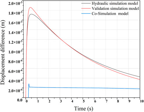
FIGURE 13. Displacement difference based on different simulation models.
5 In situ penetration tests and results
In situ measurements were conducted at Zhoushan Island, Zhejiang, China, at the coordinates
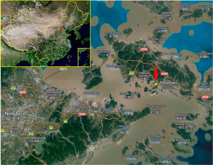
FIGURE 14. Location of test site.
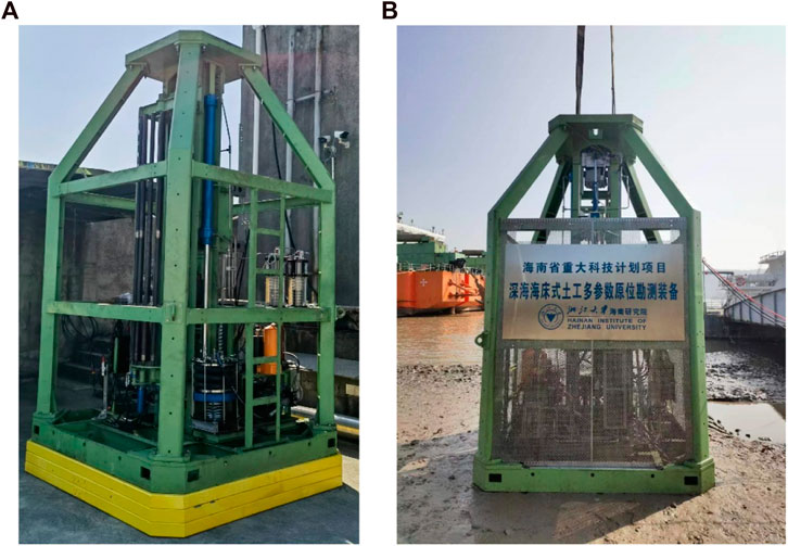
FIGURE 15. Seabed CPT conducting (A) onshore and (B) offshore tests.
The seabed CPT rig used in Zhoushan Island, Zhejiang, China, was equipped with a standard penetration speed of 2 cm/s and capable of penetrating to a total depth of 10 m. Geotechnical parameters are shown in Figure 16. The rig’s performance was assessed by analyzing key data obtained during the in situ testing process, such as penetration depth, penetration speed, and penetration resistance, as illustrated in Figure 17. Using the PID control method, we observed a maximum variation of 13–27 mm/s in the penetration rate under varying resistance conditions, with an error of approximately 35% compared to the standard penetration speed of 20 mm/s. The target penetration speed was reached after approximately 7 s. On the other hand, the SMC control method achieved a maximum variation of 18–21 mm/s in the penetration speed, with an error of about 10% relative to the standard speed, and the target speed was reached in approximately 3 s. A comparison between SMC and PID revealed that SMC can reduce the adjustment time of the penetration speed. In terms of accuracy, the PID control method exhibited quick convergence toward the target rate and low error. Our test analysis showed that the SMC control method could maintain a constant penetration rate that meets the standard penetration requirements. Therefore, we recommend the use of the SMC control method for motion simulation and actual operation of the seabed CPT rig.
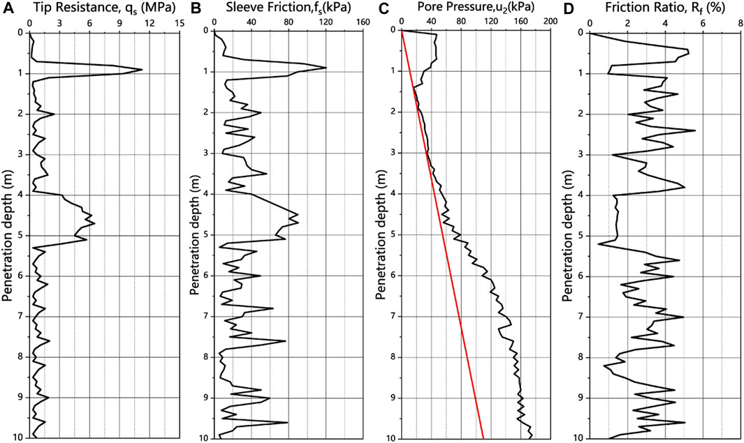
FIGURE 16. Static CPT result of a 10-m penetration depth (A) tip resistance, (B) sleeve friction, (C) pore water pressure, and (D) friction ratio.
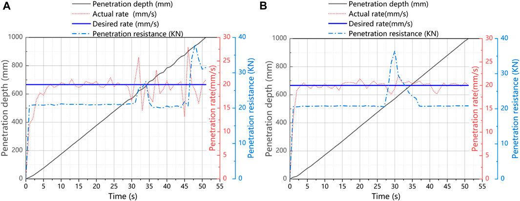
FIGURE 17. Dynamic monitoring data on the penetration process (A) based on the methods of PID and (B) SMC.
6 Summary and conclusion
A new method is presented for evaluating the physical and mechanical properties of marine sediments using the seabed CPT. The constant-rate penetration mechanism forms the basis and core part of the seabed CPT, which penetrates the probe rod and cone into the seafloor sediment. To achieve a constant penetration rate of 20 ± 5 mm/s, a hydraulic penetration system model is established and simulated using Simcenter Amesim and MATLAB/Simulink software applications. The main results of the paper are as follows:
(1) The paper presents a new method of the seabed CPT for evaluating physical and mechanical properties of sediments in the marine realm. The method allows for automatic docking and dismantling of the probe rods underwater, and a double-acting hydraulic cylinder mechanism is used to ensure a constant push rate. This rig can be operated underwater and does not require a support frame, which increases efficiency and reduces costs.
(2) The paper presents a method for identifying the constant-rate penetration electro-hydraulic servo system using Simcenter Amesim and MATLAB/Simulink software applications. A hydraulic simulation model of the penetration mechanism is established and simulated in the linear simulation mode, and the transfer function is obtained based on the simulation results. The effectiveness of the system identification method is verified by modeling with the Simcenter Amesim system.
(3) The paper establishes and simulates the sliding mode control for constant-rate penetration based on the model identification method. This includes the design of the sliding mode plane and the control law. Comparison of the simulation results shows that the SMC control is better than the PID control for adjusting the penetration speed. The SMC control method has a smaller error and a quicker tendency to the target rate.
(4) The designed method has been tested on a tidal flat in Zhoushan Island, and the functionality and feasibility of the method have been verified. The comparison between SMC and PID control shows that SMC is a suitable control method for motion simulation and actual operation for this seabed CPT method.
Data availability statement
The original contributions presented in the study are included in the article/Supplementary Material; further inquiries can be directed to the corresponding author.
Author contributions
ZR: software, data curation, writing-original draft preparation, and visualization; JC: conceptualization, supervision, and writing-reviewing and editing; JG: data curation, visualization, and investigation; BL, XH: software, visualization, and investigation; HZ: software, visualization,and investigation; HL: methodology, writing—reviewing and editing, and validation; FG: software, visualization, and writing, reviewing and editing. All authors contributed to the article and approved the submitted version.
Funding
The authors acknowledge funding by the Finance Science and Technology Project of Hainan Province (grant no. ZDKJ 202019), the Project of Sanya Yazhou Bay Science and Technology City (grant no. SCKJ-JYRC-2022-37), and the 2020 Research Program of Sanya Yazhou Bay Science and Technology City (grant no. SKYC-2020-01-001).
Acknowledgments
The authors would like to express their gratitude for the help and support given throughout the engineering process.
Conflict of interest
The authors declare that the research was conducted in the absence of any commercial or financial relationships that could be construed as a potential conflict of interest.
Publisher’s note
All claims expressed in this article are solely those of the authors and do not necessarily represent those of their affiliated organizations, or those of the publisher, the editors, and the reviewers. Any product that may be evaluated in this article, or claim that may be made by its manufacturer, is not guaranteed or endorsed by the publisher.
References
ASTM D (2020). Standard test method for electronic friction cone and piezocone penetration testing of soils[J]. ASTM International, 5778–5807.
Bai, Y. H., Chen, C., and Sun, Z. Y. (2014). Linear Analysis of electro-hydraulic valve-controlled cylinder system based on AMESim[J]. J. Syst. Simul. 26, 1430–1434.
Cheng, C., Liu, S., and Wu, H. (2020). Sliding mode observer-based fractional-order proportional–integral–derivative sliding mode control for electro-hydraulic servo systems. Proc. Institution Mech. Eng. Part C J. Mech. Eng. Sci. 234 (10), 1887–1898. doi:10.1177/0954406220903337
Ding, W. S., Liao, J. Y., and Yuan, L. Y. (2015). Design and simulation analysis of the multi-stage linear synchronous expanding and contracting hydraulic cylinder. Appl. Mech. Mater. 779, 35–41. doi:10.4028/www.scientific.net/amm.779.35
Ferrari, A., Mittica, A., and Spessa, E. (2013). Benefits of hydraulic layout over driving system in piezo-injectors and proposal of a new-concept CR injector with an integrated Minirail. Appl. energy 103, 243–255. doi:10.1016/j.apenergy.2012.09.039
Ge, Y., Chen, J., Cao, C., Zhou, P., Xu, C., Zhu, H., et al. (2022). MEMS sensor network for submarine terrain and strata deformation monitoring: Design and field experiment. IEEE Trans. Instrum. Meas. 71, 1–17. doi:10.1109/tim.2022.3218336
Guo, F., Fang, J., and Wei, J. (2017). The design and analysis of multi-stage pressure relief valve with hydraulic resistance network[J]. Recent Pat. Mech. Eng. 10 (999), 1.
Haddad, J., and Mirkin, B. (2020). Resilient perimeter control of macroscopic fundamental diagram networks under cyberattacks. Transp. Res. part B Methodol. 132, 44–59. doi:10.1016/j.trb.2019.01.020
ISSMGE (1999). International reference test procedure for the cone penetration test (CPT) and the cone penetration test with pore pressure (CPTU)[J], 16. Report of the ISSMGE Technical Committee.
Jorat, M. E., Mörz, T., Schunn, W., et al. (2014). Geotechnical offshore seabed tool (gost): A new cone penetrometer[J].
Kıyan, M., Bingöl, E., Melikoğlu, M., and Albostan, A. (2013). Modelling and simulation of a hybrid solar heating system for greenhouse applications using Matlab/Simulink. Energy Convers. Manag. 72, 147–155. doi:10.1016/j.enconman.2012.09.036
Low, H. E., Randolph, M. F., Lunne, T., Andersen, K., and Sjursen, M. (2011). Effect of soil characteristics on relative values of piezocone, T-bar and ball penetration resistances. Géotechnique 61 (8), 651–664. doi:10.1680/geot.9.p.018
Lunne, T., Powell, J. J. M., and Robertson, P. K. (2002). Cone penetration testing in geotechnical practice[M]. CRC Press.
Lunne, T. (2010). The CPT in offshore soil investigations-a historic perspective[J]. Proc. CPT 10, 71–113.
McKay, J. L., and Pedersen, T. F. (2008). The accumulation of silver in marine sediments: A link to biogenic Ba and marine productivity: Accumulation of Ag in marine sediments. Glob. Biogeochem. Cycles 22 (4). doi:10.1029/2007gb003136
Meunier, J., Sultan, N., Jegou, P., and Harmegnies, F. (2004). “First tests of penfeld: A new seabed penetrometer,” in Proceedings of the Fourteenth International Offshore and Polar Engineering Conference (Toulon, France), 338–345.
Ngo, Q. H., Nguyen, N. P., Nguyen, C. N., Tran, T. H., and Ha, Q. P. (2017). Fuzzy sliding mode control of an offshore container crane. Ocean. Eng. 140, 125–134. doi:10.1016/j.oceaneng.2017.05.019
Ren, Z., Zhou, F., Zhu, H., Zhang, P., Chen, J., Zhou, P., et al. (2021). Analysis and research on mobile drilling rig for deep seabed shallow strata. Mar. Technol. Soc. J. 55 (2), 81–93. doi:10.4031/mtsj.55.2.7
Sa, Y., Zhu, Z., Tang, Y., Li, X., and Shen, G. (2022). Adaptive dynamic surface control using nonlinear disturbance observers for position tracking of electro-hydraulic servo systems. Proc. Institution Mech. Eng. Part I J. Syst. Control Eng. 236 (3), 634–653. doi:10.1177/09596518211037096
Seidman, J., and Lim, R. M. (2011). Shear wave velocity testing using a seismic cone penetrometer in bentonite backfilled boreholes in Hawaii[M]. Geo-Frontiers Adv. Geotechnical Eng., 2317–2324.
Sheng, D., Kelly, R., Pineda, J., et al. (2014). Numerical study of rate effects in cone penetration test[C]//3rd international symposium on cone penetration testing, 419–428.
Thien, R. T. Y., and Kim, Y. (2018). Decentralized formation flight via PID and integral sliding mode control. Aerosp. Sci. Technol. 81, 322–332. doi:10.1016/j.ast.2018.08.011
Tom, Lunne (2012). The Fourth James K. Mitchell Lecture: The CPT in offshore soil investigations a historic perspective[J]. Geomechanics Geoengin. 7 (2).
Wang, X. X., He, G., and Gao, R. (2019). PID sliding mode control for electro-hydraulic servo system[J]. J. Phys. Conf. Ser. 1168 (2).
Wang, Z., Jun, F., Zhijian, S., and Qiang, S. (2017). Study on speed sensor-less vector control of induction motors based on AMEsim-matlab/simulink simulation. Energy Procedia 105, 2378–2383. doi:10.1016/j.egypro.2017.03.682
XieChenGuo, N. X. J. J. (2013). Simulation analysis of proportional valve controlled cylinder hydraulic system based on AMESim. Mach. Tool Hydraulics 668, 420–425. doi:10.4028/www.scientific.net/amr.668.420
Keywords: seabed CPT, constant-rate penetration, transfer function, sliding-mode variable structure controller, physical and mechanical properties
Citation: Ren Z, Chen J, Guo J, Liu B, Hu X, Zhou H, Liu H and Gao F (2023) Analysis and research on the constant-rate penetration mechanism of the seabed cone penetration test system. Front. Mech. Eng 9:1110951. doi: 10.3389/fmech.2023.1110951
Received: 14 December 2022; Accepted: 05 June 2023;
Published: 20 June 2023.
Edited by:
Yihan Xing, University of Stavanger, NorwayReviewed by:
Aman Garg, The Northcap University, IndiaChengxing Yang, Central South University, China
Pei Li, Xi’an Jiaotong University, China
Copyright © 2023 Ren, Chen, Guo, Liu, Hu, Zhou, Liu and Gao. This is an open-access article distributed under the terms of the Creative Commons Attribution License (CC BY). The use, distribution or reproduction in other forums is permitted, provided the original author(s) and the copyright owner(s) are credited and that the original publication in this journal is cited, in accordance with accepted academic practice. No use, distribution or reproduction is permitted which does not comply with these terms.
*Correspondence: Jiawang Chen, YXJ3YW5nQHpqdS5lZHUuY24=