 Xin Lin
 Bing Liu
 Anchao Shen1,2
 Kunpeng Zhu
- 1Precision Manufacturing Institute, Wuhan University of Science and Technology, Wuhan, China
- 2Key Laboratory of Metallurgical Equipment and Control Technology, Ministry of Education, Wuhan University of Science and Technology, Wuhan, China
- 3Institute of Intelligent Machines, Hefei Institutes of Physical Science, Chinese Academy of Sciences, Changzhou, Jiangsu, China
In situ monitoring during the selective laser melting (SLM) process is a promising solution to mitigate defects and improve the quality of as-built parts. However, the existing monitoring platform lacks collaborative control of the process monitoring components, and as a result, it cannot realize a real-time and accurate signal acquisition at a close distance and multiple angles during the whole printing process. In this paper, driven by multiple motors, an off-axis monitoring platform is constructed that enables movement in conjunction with the scraper and laser beam. A fuzzy control-based velocity optimization is proposed to avoid the shock effect on the imaging quality of the CMOS camera and the collision of the scraper and laser. The error between the current location and target location of the molten pool is utilized as the input of the fuzzy controller. Then, the parameters of the PI controller of the stepping motor are dynamically adjusted. ADAMS and SIMULINK co-simulation are conducted to verify the feasibility of the fuzzy algorithm. Finally, the experiment of collaborative motion and the responses of each module are conducted. The results show that with the proposed collaborative platform, the response speed of the system is improved by about 49.6%, and the initial speed of the motor is decreased by about 12.6%, thus avoiding excessive acceleration of the motor. The response time of each motor is ahead of schedule by about 31.8%, which meets the requirements of motion response for SLM process monitoring.
1 Introduction
Selective laser melting technology is a kind of metal additive manufacturing technology that is widely used in industrial fields, biomedicine, aerospace, and other manufacturing fields. However, the development of the SLM process has been hindered due to defects such as spheroidization, warping deformation, and fracture in the printing process (Higashi and Ozaki, 2021; Jia et al., 2021; Wang et al., 2022), which are not only caused by the mechanical properties and geometry of powder particles but also by the process parameters, such as the laser power of the SLM device, the thickness of the powder layer, the laser scanning speed, and others (Grasso et al., 2018; Caiazzo et al., 2019; Ökten and Biyikoğlu, 2021). The powder exhibits different states during the process of heating, melting, and solidification, which tend to release complex acoustic, optical, and thermal signals. Therefore, it is of great significance to monitor the complex signals of different powder states and realize the online adjustment of the parameters in the printing process for improving the quality of the printing parts (Aminzadeh and Kurfess, 2019; Peng et al., 2022).
However, achieving the acquisition of the signal in the SLM process is still a challenge. The optical signal in the SLM process mainly comes from the molten pool, spatters, and other phenomena produced in the process of powder melting. The acquiring and processing of optical information in the molten pool via optical devices is a common method for monitoring laser printing (Lin et al., 2022a). Lin et al. (Lin et al., 2022b) used a high-speed camera to record the molten processing and analyzed the dynamic characteristics of the molten pool. The monitoring methods, according to the installation position of the high-speed camera, can be divided into off-axis and coaxial monitoring. The off-axis method is generally achieved by mounting the camera lens at a constant angle and without affecting the printing equipment’s optical path to the forming area. Gunenthiram et al. (Gunenthiram et al., 2018) set the high-speed camera lens at a 0° and 60° angle off the forming area to monitor the ejecting powders and spatters. Montazeri et al. (Montazeri and Rao, 2018) mounted a high-speed camera parallel to the observation window and off the forming plane at 43° to capture the thermal form of the molten pool at a distance of 162 mm. However, due to the effort of the observation window, the long shooting distance of the camera, and the small size of the molten pool, it is difficult for the sensors to focus on the target. Moreover, the camera cannot successfully identify the molten pool due to the filter window (Matilainen et al., 2015). Coaxial monitoring is a method of collecting reflection signals in the molten pool simultaneously on the laser optical path (Lane and Yeung, 2020). The light path of the high-speed camera is set parallel to the laser light path, which ensures that the high-speed camera can accurately capture the light spot of the molten pool (Li et al., 2022). Alkahari et al. (Alkahari et al., 2014) photographed the molten pool on an experimental SLM device with a high-speed camera and telescope lens perpendicular to the forming area.
Whether coaxial or off-axis monitoring, the common disadvantage is that they cannot track the target from different angles, which would provide more valuable information. Due to the poor collaboration between the SLM device and monitoring device, it is difficult to realize real-time and efficient signal acquisition in the whole printing process. In addition, if the monitoring platform is installed in the forming chamber, it is necessary to consider the interference from the closed chamber space, scraper, dust, laser, and spatters caused by the interaction between the laser and the powder. Therefore, the location of the monitoring platform at each time beat is accurate and timely to avoid collisions. The space in the original forming chamber is redivided (in Figure 1) to realize the collaborative control of the monitoring device and SLM device driven by multiple motors in the forming chamber. The specific implementation method is shown in the following chapter. In the collaborative control system, the motors’ sensors drive the horizontal X and Y motion, pitch motion, and rotation motion. In this paper, the stepper motor is selected to drive the horizontal movement according to the comprehensive consideration of the control accuracy, application scene, and operation cost.
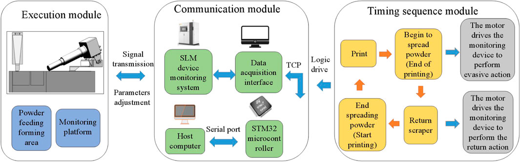
FIGURE 1. Framework of the whole control system.
During the laser acting on the powder, the size of the target molten pool is small, with a diameter 0.1 mm, and the laser scanning speed can reach 3,000 mm/s. Hence, the stepper motor for driving the motion of the monitoring platform is required to achieve a high-accuracy positioning smoothly and rapidly to photograph the small molten pool. Due to the cantilever structure of the monitoring platform, the unstable speed response could easily lead to dislocation and shaking of the sensors. The stepper motor’s operating torque decreases with the increase of speed, and the strength of the current is related to the frequency of the control signals sent by its controller (Kukla et al. (Kukla et al., 2016)). Tarkowski et al. (Tarkowski et al., 2016) studied the frequency of the stepper motor in the starting process, and their results showed that selecting a proper starting frequency for the stepper motor could effectively reduce the problems of overshoot or out of step. The acceleration and deceleration curves of the stepper motor are very important for the stable operation of the system. Zhang et al. (Zhang et al., 2017) designed a new type of S-shaped velocity running curve, which had less vibration and was more stable than the traditional trapezoidal curve.
To ensure the motion’s stability and improve the accuracy of the monitoring device in the collaborative control system, an intelligent algorithm to optimize the parameters of the control process is an attractive research topic (Hu, 2022). The fuzzy control algorithm has been verified to adjust the parameters of the control object by establishing fuzzy rules in line with different running states (Jirasuwankul and Manop, 2017). Wang et al. (Wang and Cao, 2020) optimized the sliding mode observer in the closed-loop control system of stepper motor by using a fuzzy algorithm and realized the optimal control by adaptively adjusting the observer gain, and the results showed a good tracking effect on its speed and displacement through experiments. Ghanooni et al. (Ghanooni et al., 2020) proposed an adaptive fuzzy control algorithm to improve the robustness of speed tracking for a stepper motor, which could eliminate the resonance and vibration under different working conditions and have advantages in a non-linear system and in improving speed response accuracy.
In conclusion, the collaborative control method of the monitoring platform realizes the multi-angle close-range acquisition of molten pool signals by avoiding SLM scraper movement. Therefore, it is meaningful to optimize the X-direction driving device of the monitoring platform. The optimization of the movement of the monitoring device to evade the scraper is to ensure the monitoring process is safer and more reliable. Other motions are required, such as rotation for adjusting the poses of the camera, but they have no limit of rigorous time. The main work of this paper is as follows.
(1) The dynamical model of the co-simulation platform is established through the ADAMS virtual prototype. The timing logic of the collaborative control and the stepper motor drive system are constructed based on the SIMULINK model.
(2) The performance of the proposed fuzzy algorithm is compared with the classical algorithm through a co-simulation and experiment to verify its feasibility. The cooperation between the SLM device and monitoring platform is then tested to validate the collaborative control system.
2 Methods
2.1 Modules
The collaborative control system comprises an execution module, a communication module, and a timing sequence module (in Figure 1). The functions and implementation methods of each module are introduced as follows.
(1) Executive module. The executive module includes a monitoring device and a printing device. The monitoring device mainly consists of a mechanical platform and four motors. The CMOS camera and other sensors perform XY translation motion, rotation motion, and pitching motion in the forming chamber, and the corresponding motors are defined as X, Y, Z, and F motors (in Figure 2). The X motor and Z motor are mainly used in conjunction with the motion of the scraper to achieve collaborative control. The F motor is mainly used to adjust the pitch angle of the CMOS camera, so as to capture the morphologies of the molten pool at different angles, while the Y motor is mainly used to adjust the horizontal position of the sensors to find the location of the target molten pool.
(2) Communication module. The STM32 microcontroller works as the control unit for the monitoring platform. On the one hand, it receives signals of the scraper movement (end of powder spreading) and laser signal (end of printing) through Ethernet from the SLM device. On the other hand, it sends control signals to the motors. A host computer is used to adjust the running parameters of the motors and displays the running state of the monitoring platform.
(3) Timing sequence module. This module realizes the collaborative control between the SLM device and the monitoring platform by analyzing the communication signals from the SLM device. According to the operation of SLM, it defines the motion timing of the monitoring platform. The purpose of the timing logic is to efficiently reorder and match the printing process and ensure that the sensors and the scraper do not collide during the powder feeding, laser working, and the monitoring platform moving.
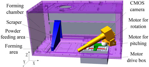
FIGURE 2. ADAMS simulation model.
2.2 Modeling and simulation of collaborative control system
The ADAMS and SIMULINK co-simulation is used to simulate the collaborative control process of the SLM device and monitoring, so as to effectively test whether the motion of sensors interferes with the normal operation of the SLM device and whether the designed motion logic is reasonable. SIMULINK can also analyze and simulate the composition principle of the stepper motor control.
(1) Establishment of ADAMS model. The mechanical models of the SLM device and monitoring platform are imported into the ADAMS software. The motion pairs and the drivers are added in the corresponding position. The cooperative control proposed in this paper is mainly to realize the monitoring device to avoid the scraper safely and reliably, which is mainly realized by the motion of the X motor and Z motor in the monitoring platform. Meanwhile, the Y motor and F motor only serve as driving sensors for local motion adjustment, whose motion is neglected.
The drivers configurations of the scraper and Z motor are simplified, where the prismatic pair and revolute pair are established, respectively, and their displacements are indexed as driving variables. The X-direction driving device of the monitoring platform is established, which is mainly composed of the stepper motor, bearing support, ball screw, and guide rail. The revolute pair, spiral pair, and prismatic pair are added in the corresponding positions, and the torque of the stepper motor is taken as the driving variable of the motor (in Figure 2).
(2) Theoretical basis of simulation. The movement of the CMOS camera and other sensors in the horizontal X direction is driven by a two-phase hybrid stepper motor, whose mathematical model consists of a mechanical and voltage equation as follows:
where the w indexes the speed of a stepper motor and TAB for the friction factor. The electromagnetic torque works for motor rotation and friction loss. In this paper, the magnetic motive force generated by the stator winding is ignored. The permanent magnet torque generated by the rotor permanent magnet is established, and its unidirectional torque of the A-phase (Stuebig and Ponick, 2012; Lu et al., 2016) is expressed as
where the Kt defines the torque coefficient, which is related to the geometric size of the motor and the magnetic motive force of the permanent magnet in the rotor. The θe indicates the misalignment angle between the stator tooth axis of the A-phase and the rotor tooth axis. The A-phase voltage balance equation of a two-phase hybrid stepper motor is as follows:
where VA defines the A-phase voltage. According to the Faraday’s law of electromagnetic induction, the opposite electromotive force of the A-phase is UA:
where the Nr defines the number of the rotor’s teeth. In this paper, the mathematical model of the stepper motor is established by setting the angle between two phases A and B as 90°. Similarly, the formula of the B-phase can be obtained by replacing θ variable in Eqs. 2–4 with θ-π/2 variable.
A co-simulation platform including SIMULINK and ADAMS (in Figure 3) is established to simulate the motion control system with stepper motors and the collaborative control with timing sequences.
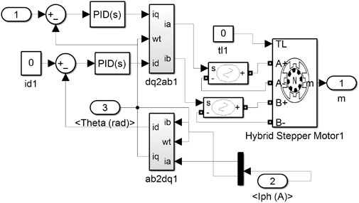
FIGURE 3. The block diagram of stepper motor control system.
For the classical stepper motor PI control, as shown in (5), its output is the pulse frequency of the controller. The e(t) defines the error between the controller target displacement (speed), and the displacement (speed) is measured by the encoder. In classic control, the proportional coefficient Kp mainly affects the response speed of the motor, and the integral coefficient Ki mainly aims at eliminating steady-state errors of the system.
(3) The stepper motor model. Based on the nominal parameters (a Leadshine’s 57CME13D stepper motor), the resistance of a hybrid stepper motor is set as 0.42 Ω. The inductance is set as 1.6 Mh, and the rotor inertia as 0.3 kg cm2. The friction coefficient of the motor is set to 1e-3N·m·s. The SIMULINK model of the stepper motor is established based on the mathematical model of a two-phase hybrid stepper motor.
To simulate the subdivision drive system of the stepper motor, the current loop is constructed with the PI controller, Park transforms, and inverse transform (Lyshevski, 2014), as shown in Figure 3. For a closed-loop control with stepper motors, the speed loop is generally defined as the inner loop and the displacement loop as the outer loop in the cascade PI control.
As to establish the stepper motor model, multiple groups of PI parameters are selected for its displacement loop and speed loop. For the model debugging, according to the basic principle of “the inner loop first, then the outer loop”, the displacement loop controller outsider is added until the speed loop insider reaches a fast, stable, and accurate control level. When adjusting the PI parameters, the proportional coefficient Kp is first debugged until it reaches a critical stable state. When the system has steady-state error, then we adjust the integral coefficient Ki. The Kp and the Ki in the displacement loop are set to 23 and 12. In the speed loop, the Kp value is set to 0.16, and the Ki value is set to 12.
(4) Timing sequence module. According to the motion sequence of scraper and the monitoring platform in Figure 1, the corresponding displacement vs. time is set in the SIGNAL BUILDER module in SIMULINK. It is required that the X motor and the Z motor trigger the motion command at the same time when the scraper returns or when the SLM device finishes printing a layer.
(5) Importing an ADAMS mechanical model. The interface to communicate with the SIMULINK software (as shown in adams_sub in Figure 4) is established in ADAMS. The co-simulation platform built in this paper is shown in Figure 4
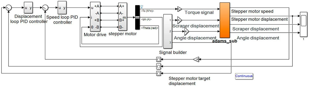
FIGURE 4. The block diagram of collaborative control system for co-simulation implemented in SIMULINK.
A displacement vs. time curve of motors and scraper after running the simulation is shown in Figure 5. The SLM device sends signals to the monitoring platform at the end of powder feeding (time t0) and end of printing (time t2). At the time t0, the X motor and the Z motor execute the return. The laser works from t1 to t2. The monitoring platform executes the evasion command at the time t2, and the scraper begins to spread the powder.
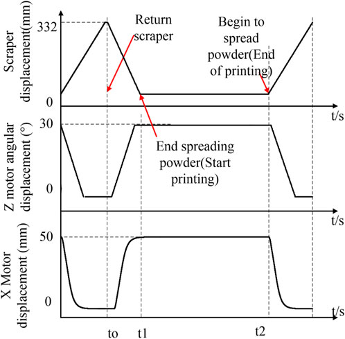
FIGURE 5. The displacement response curves of X motor, Z motor, and scraper in collaborative control are obtained by SIMULINK and ADAMS co-simulation.
In Figure 6, the velocity and velocity target response curves of X motor in collaborative control are obtained by the SIMULINK and ADAMS co-simulation. As can be seen, the response of the control system has the problem of faster acceleration and slower deceleration. Through analyzing the change trend of the target speed curve, the target speed increases too fast in the early stage and decreases slowly in the later stage. For a stepper motor, fast acceleration makes it easy to lead to the motor overshoot and lose steps. Meanwhile slow deceleration can easily cause the motor to have a low-frequency vibration, which leads to the CMOS cameras collecting blurred images. These are the reasons for optimizing the control system.
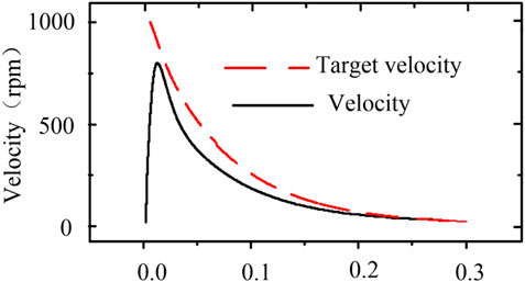
FIGURE 6. The velocity and velocity target response curve of X motor under 50 mm target displacement is obtained by co-simulation.
2.3 Design of a fuzzy algorithm
For the PI controller, the integral coefficient Ki eliminates the steady-state error of the system. If its value is too small, the steady-state error of the system is difficult to eliminate. If its value is too large, the integral saturation phenomenon will occur at the initial stage of the response. Therefore, it is difficult to balance the parameter Ki in the control process. The proportional coefficient Kp mainly affects the response speed of the controller in the PI controller. Its control effect is more obvious. Therefore, the fuzzy controller is proposed to determine the proportional coefficient Kp and achieve smooth motion safely and reliably.
During the movement of the sensors, the error between its position and that of the molten pool reflects the phase of its movement (acceleration, uniform speed, or deceleration). The fuzzy control algorithm needs to optimize the acceleration and deceleration process of the stepper motor. Therefore, this error is selected as the input of the fuzzy controller. In order to meet the sensor’s different displacement requirements, the output domain is adjusted by using telescopic coefficients. The fuzzy control system is shown in Figure 7, where e indicates the displacement loop error and Kp1 and Kp2 are the proportional coefficients of the displacement loop and speed loop PI controllers, respectively.
(1) Fuzzification of input and output. The error between the right limit of the monitoring device and the molten pool is 50 mm, so the input domain of the fuzzy controller is set as [0, 50]. The physical domains of outputs Kp1 and Kp2 are obtained through repeatedly debugging, and the final domains of the outputs are set to [10, 60] and [0.1, 0.4], respectively. Then, the physical domain is normalized as e, Kp1, Kp2 = { −3, −2, −1, 0, 1, 2, 3}, and the corresponding fuzzy subset is e, Kp1, Kp2 = {NB, NM, NS, ZE, PS, PM, PB}. The {NB, NM, NS, ZE, PS, PM, PB} is obtained by mapping the final domains of the outputs following a triangular membership function, as shown in Figure 8, into the interval of e, Kp1, Kp2.
(2) Fuzzy rules based on speed optimization. The speed change trend of the stepper motor in the X direction, combined with the proportional coefficients Kp1 and Kp2 in the PI controller, mainly affects the speed response of the system. Based on this, the fuzzy rules are established.

FIGURE 7. The block diagram of fuzzy control system in the variable domain.
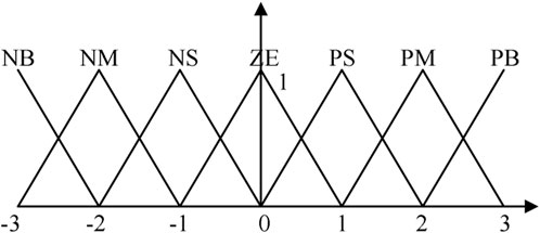
FIGURE 8. The membership function with input and output variables.
In the starting process of the motor, the value of e is large. To avoid overshoot damaging the motor and serious shock as a result of the imaging quality of the CMOS camera, the Kp1 in the displacement loop is adjusted to a small value so that the target value of the speed reduces slowly. Moreover, the response speed in the speed loop decreases as the value of Kp2 is adjusted to small, aiming to form a relatively smooth speed curve.
When the monitoring device is reaching the target position, that is, the value of e is small, in order to avoid a low-frequency vibration of the stepper motor, the proportional coefficient of the speed loop and the displacement loop are set to a large value so that the system can respond quickly.
In the whole one-way movement of the monitoring device, Kp1 and Kp2 gradually increase with the value of e decreasing, which is conducive to the stable operation of the system. The fuzzy rule statements are shown in Table 1.
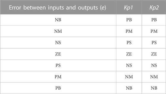
TABLE 1. Fuzzy rule table.
The fuzzy rules establish the relationship between the input and output of the fuzzy variables. Then, fuzzy reasoning and defuzzification are given. The fuzzy reasoning method used in this paper is MAMDANI (Melin and Castillo, 2005; Zhang et al., 2018), which is realized by the Fuzzy Logic Designer plug-in in SIMULINK.
Defuzzification is to obtain the actual control amount by calculating the fuzzy vectors based on the fuzzy reasoning method. This paper uses the center of gravity method, and its operation formula is as follows:
where the f is the output control amount of the fuzzy controller, C* is the element in the output fuzzy set, and μC*(i) is the membership degree of the corresponding element.
(3) Adjustment strategy in the output domain. For the proportional control, the outputs of the speed loop and displacement loop are determined according to the proportional coefficient Kp and the error e. When different target displacements are selected in the monitoring platform, the same fuzzy output domain may lead to too large or too small a speed of the stepper motor. Therefore, the output domain under different target displacements is adjusted as follows by telescopic coefficient a:
where the u(k) is the output of the proportional controller. The telescopic coefficient a in the output domain is determined according to the target displacement of the camera, and the target displacement (50 mm) is taken as the benchmark. When the target displacement value is greater than 50 mm, the value a is selected as less than 1, or if the target displacement is less than 50 mm, the value of a is chosen to be greater than 1. The specific parameter settings of a are mentioned in Section 3.2.
3 Experiments and analysis
3.1 Co-simulation for a fuzzy controller
To verify the implementation effect of the collaborative control system under the optimization of the fuzzy control algorithm, the velocity of the monitoring device and the moment frequency characteristics of the stepper motor are contrastively analyzed. On the co-simulation platform, as shown in Figure 9, Fuzzy Logic Controller in SIMULINK is used to realize the physical domain of the fuzzy control object, fuzzy rules, and MAMDANI fuzzy reasoning method.
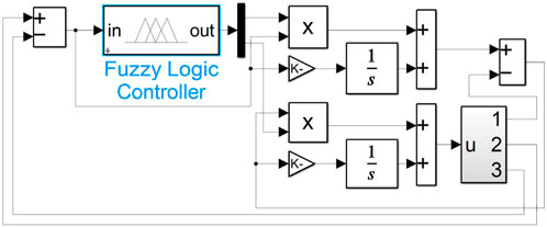
FIGURE 9. The diagram of SIMULINK fuzzy control simulation.
In Figure 10, the output velocity and torques are compared with the classical PI algorithm, and the displacement of the monitoring device is set as 50 mm.
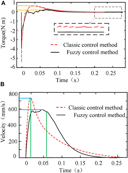
FIGURE 10. The response curve of X motor to 50 mm target displacement is obtained from co-simulation: (A) the motor torque compared with the classical PI algorithm and the fuzzy control algorithm and (B) the corresponding velocity comparison.
When the stepper motor drives, the monitoring device moves in the X direction, and the stepper motor’s output torque and input pulse frequency meet the following requirements (Ji et al., 2012):
where T0 is the time constant for the starting torque of the stepper motor. Its torque decreases with the increase of the pulse frequency. A high starting torque will make the rotor unable to synchronously rotate with the stator magnetic field, thus causing the motor to lose step or stop rotating (Ji et al., 2012). In Figure 10A and Table 2, compared with the classical PI algorithm, the fuzzy PI algorithm reduces the proportional coefficients Kp1 and Kp2 at the start of the motor and reduces the response speed of the system. Thus, the fuzzy PI algorithm has a smaller starting torque, which decreases slowly with the speed increasing, and improves the utilization rate of the torque.
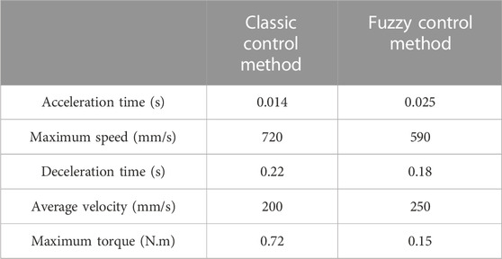
TABLE 2. Simulation comparison between classical control and fuzzy control.
When the monitoring device is reaching the target position, as shown in Figure 10B, at time t = 0.1 s–0.15 s, the velocity value of the motor under fuzzy control decreases more sharply than that under classical PI control, which still has low speed movement and an unstable torque at t = 0.2 s–0.25 s.
The fuzzy PI algorithm increases the proportional coefficients Kp1 and Kp2 gradually in the process of moving, which speeds up the response speed of the system when the motor is about to stop. This avoids speed delay and torque instability, and so it ensures the safe and stable operation of the monitoring device.
3.2 Experiment for a fuzzy controller
To verify the fuzzy control algorithm for sensors’ motion in the X direction, Leadshine’s 57CME13D stepper motor with an encoder and Embedfire’s EBF-MSD4805 stepper motor driver is used. The STM32 microcontroller is used as the controller. According to the fuzzy controller obtained by co-simulation, as above mentioned, the fuzzy PI controller of the stepper motor is designed.
Through debugging, the physical domain of the input of the fuzzy controller e is divided into several intervals, and the corresponding Kp1 and Kp2 are set for different intervals in Table 3. An incremental encoder, microcontroller, and host computer are utilized to get, process, and output the velocity and displacement information of the stepper motor. The PI sampling frequency is set to 20 ms. The displacement loop Kp is set to 0.011. In the speed loop, the Kp is set to 0.01, and the Ki is set to 0.093.
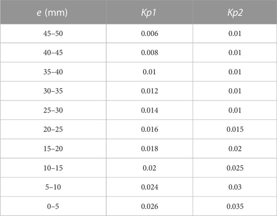
TABLE 3. Fuzzy controller parameter setting.
The results of the experimental test are shown in Figure 11 and Table 4. Since the Kp value determines the speed response of the PI controller—as demonstrated in Figure 11A—as the monitoring device approaches the target position, the strategy of increasing Kp1 is adopted to obtain the accelerating velocity response of the displacement loop controller in the whole process. Moreover, its response speed is slower than that of the classical PI controller at the early stage (0–2 s in Figure 11B) and faster than that of the classical PI controller at the later stage (3–4 s in Figure 11B). Thus, the fuzzy algorithm optimization of the displacement loop is helpful to get an optimal speed. The purpose of the fuzzy optimization of Kp2 in the speed loop is to achieve an optimal control, that is, to change the output change of the controller from slow to fast in the whole control process. The optimized results of velocity and displacement are shown in Figures 11B, 11 (C).
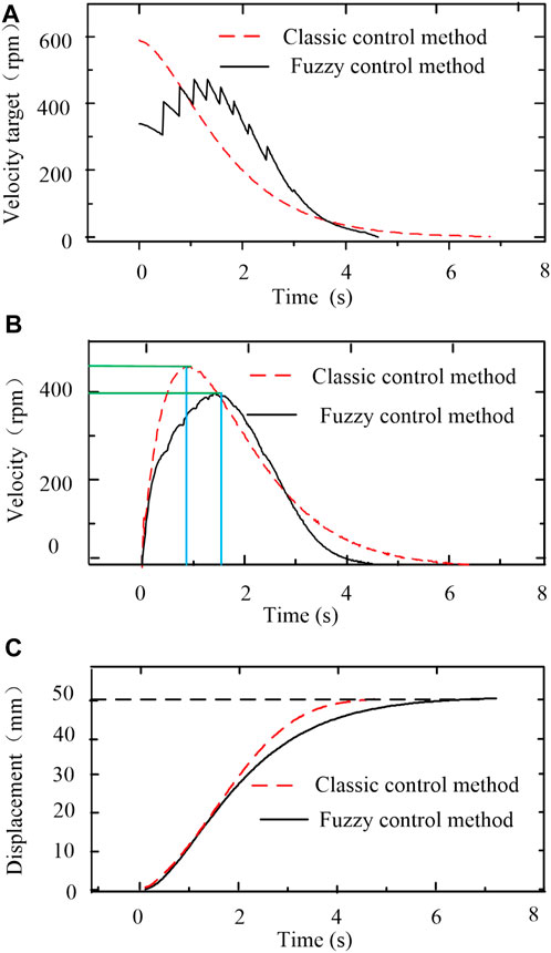
FIGURE 11. The response curves of X motor under 50 mm target displacement are tested experimentally. (A) Shows the comparison curve of the speed target value. (B, C) are the corresponding velocity and displacement curves.
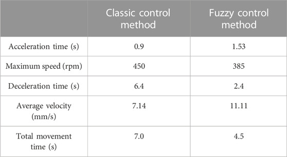
TABLE 4. Experiment comparison between classical and fuzzy control.
Compared with Figures 10, 11, the optimal results are similar between the simulation and the experiment. According to the results of the simulation or experiment in Table 2 and Table 4, it is clearly found that the acceleration process of the stepper motor of the fuzzy control is slower than that of the classical control method. The deceleration time is faster, and the utilization rate of the torque is improved under the premise of improving the average velocity, which indicates the fuzzy control method could achieve a smooth and rapid control.
To verify the optimization of the variable domain fuzzy controller to achieve different target displacements, the telescopic coefficient is set in Table 5, and the fuzzy control with and without variable theory domain controller are compared (as shown in Figure 12). According to the curves, the variable domain controller can significantly prevent too large or too small a velocity of the monitoring device (x = 60 and x = 20 in Figure 12A), resulting in reducing the out of step or overshoot of the stepper motor to a certain extent.

TABLE 5. Comparisons of average speed, maximum speed, and running time between classical PI algorithm and fuzzy control algorithm of X motor under different target displacements.
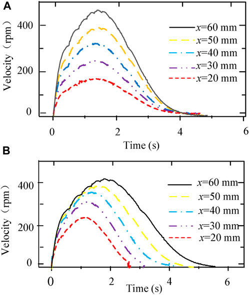
FIGURE 12. The velocity response curves of X motor to different target displacements (A) without variable domain and (B) with variable domain are tested through experiments.
In Table 5, by averaging the optimal ratios of the different target displacements, the fuzzy variable domain controller obtains the average response speed of the stepper motor, which increases by 49.6%, while the maximum speed decreases by 12.6% compared with the classical PI algorithm.
3.3 Implementation and test analysis of collaborative control
To verify the practical performance in the collaborative control system, the collaborative and stability of the timing between the SLM device and the monitoring platform are tested (as shown in Figure 13). The STM32F407 microcontroller is used as a server to receive the printing states from the SLM device client through TCP communication. The single chip microcomputer connects to the SLM through the network port, and the printed information of the SLM device is sent to the host computer through the serial port for display.

FIGURE 13. Experimental test platform.
The monitoring device controls its four motors to realize the change of the direction and position of the camera lens in order to collect information about the molten pool status from multiple angles. In addition, since the monitoring platform is independently designed by the laboratory, other sensors can also be installed in corresponding positions according to the experimental need.
During the experimental test, the different motion states of the monitoring device and the position of a scraper at different times are recorded (in Figure 14), and the displacement of the monitoring device in the X direction and of the scraper during the printing process of each layer are acquired and analyzed (Figure 15). The STM32 controller communicates with the SLM device through Netconn’s interface under the Lwip protocol stack, and then it confirms the device’s online states through heartbeat packets and receives the printed status information in real time.
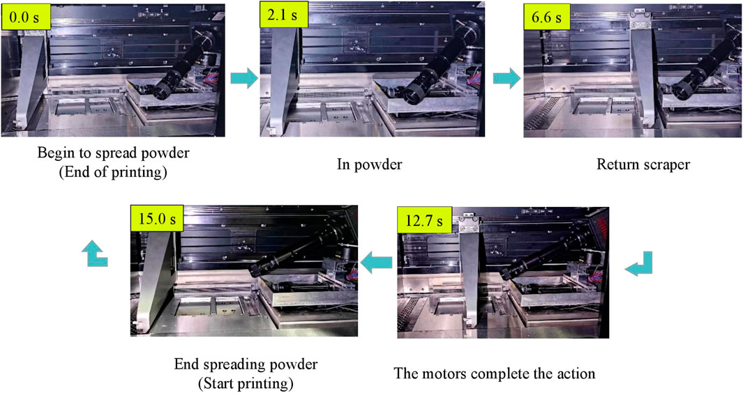
FIGURE 14. The monitoring device and SLM device are shown in different stages of collaborative control.
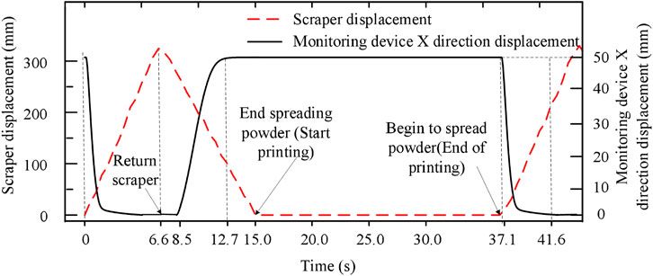
FIGURE 15. Displacement response curves of scraper and monitoring device during collaborative motion.
The movement velocity of the scraper is set to 50 mm/s, and the displacement of the scraper in the X direction is set to 332 mm. The process of powder feeding and return both take 6.6 s. The rotation angle of the Z motor is 30°, which takes about 3.8 s. It takes 4.5 s for the monitoring platform to move 50 mm in the X direction. According to the vacant time between the movement of the scraper and platform, the monitoring device completes the evasive action ahead of schedule by about 31.8%. Therefore, the collaborative control system can meet the requirements of the stable motion of the monitoring device, responsively evading the scraper and without affecting the normal printing process.
4 Conclusion
Since the existing SLM online monitoring is limited by the enclosed space and by multiple sensors and multiple platforms with poor collaborative motions, this paper proposes an off-axis monitoring platform and a control system in the closed forming chamber of an SLM device. The following conclusions are reached.
(1) The co-simulation based on ADAMS and SIMULINK can correctly simulate the timing logic and dynamic characteristics of the motion.
(2) The speed curve of the monitoring device in the X direction is optimized through a fuzzy algorithm, and the response curves of the monitoring device for different displacements are optimized by using the variable domain controller. Firstly, on the premise of improving the overall response speed (increased by about 49.6%), the speed of the motor in the starting process is decreased by about 12.6%, which avoids excessive acceleration of the stepper motor causing out of step or overshoot. Secondly, it reduces the movement time of the motor by about 60% in the deceleration process, which results in avoiding the influence of low-frequency vibration of the motor so that the stability and reliability of the monitoring platform are improved.
(3) The stepper motor’s speed meets the response requirements of the SLM device (the response time of the monitoring device is shortened by about 31.8%), which verifies the feasibility of the collaborative control method in SLM monitoring.
(4) The molten pool monitoring described in this paper is designed in the focus area of the CMOS camera, which focuses along the Y-axis, while the images of the molten pool when large parts are printed cannot be real-time photographed before adjusting the angles of the camera.
(5) In future work, the next step of SLM molten pool monitoring should be carried out to realize the synchronous triggering of sensor data acquisition and the collaborative control system and the processing and analysis of molten pool image information.
Data availability statement
The raw data supporting the conclusion of this article will be made available by the authors, without undue reservation.
Author contributions
XL: Conceptualization, Methodology, Writing—review and editing. BL: Experiment, Validation, Software, Writing—draft and editing. AS: Experiment. ZC: Experiment. KZ: Supervision, Conceptualization, Formal analysis, Writing—review and editing.
Funding
This work was supported in part by the National Natural Science Foundation of China (Grant Nos 52175481 and 51875379).
Conflict of interest
The authors declare that the research was conducted in the absence of any commercial or financial relationships that could be construed as a potential conflict of interest.
Publisher’s note
All claims expressed in this article are solely those of the authors and do not necessarily represent those of their affiliated organizations, or those of the publisher, the editors and the reviewers. Any product that may be evaluated in this article, or claim that may be made by its manufacturer, is not guaranteed or endorsed by the publisher.
References
Alkahari, R., Furumoto, T., Ueda, T., and Hosokawa, A. (2014). Consolidation characteristics of ferrous-based metal powder in additive manufacturing. J. Adv. Mech. Des. Syst. Manuf. 8, 0009. doi:10.1299/jamdsm.2014jamdsm0009
Aminzadeh, M., and Kurfess, T. R. (2019). Online quality inspection using Bayesian classification in powder-bed additive manufacturing from high-resolution visual camera images. J. Intelligent Manuf. 30, 2505–2523. doi:10.1007/s10845-018-1412-0
Caiazzo, F., Alfieri, V., Aliberti, M. V., and Argenio, P. (2019). Influence of building parameters on surface aspect and roughness in additive manufactured metal parts. Key Eng. Mater. 813, 104–109. doi:10.4028/www.scientific.net/KEM.813.104
Ghanooni, P., Yazdani, A. M., Mahmoudi, A., MahmoudZadeh, S., Ahmadi Movahed, M., and Fathi, M. (2020). Robust precise trajectory tracking of hybrid stepper motor using adaptive critic-based neuro-fuzzy controller. Comput. Electr. Eng. 81, 106535. doi:10.1016/j.compeleceng.2019.106535
Grasso, M., Demir, A. G., Previtali, B., and Colosimo, B. M. (2018). In situ monitoring of selective laser melting of zinc powder via infrared imaging of the process plume. Robotics Computer-Integrated Manuf. 49, 229–239. doi:10.1016/j.rcim.2017.07.001
Gunenthiram, V., Peyre, P., Schneider, M., Dal, M., Coste, F., Koutiri, I., et al. (2018). Experimental analysis of spatter generation and melt-pool behavior during the powder bed laser beam melting process. J. Mater. Process. Tech 251, 376–386. doi:10.1016/j.jmatprotec.2017.08.012
Higashi, M., and Ozaki, T. (2021). Selective laser melting of MoSiBTiC alloy with plasma-spheroidized powder: Microstructure and mechanical property. Mater. Charact. 172, 110888. doi:10.1016/j.matchar.2021.110888
Hu, K. (2022). “Research on fuzzy control of stepper motor based on adaptive neuro-fuzzy inference system,” in International Conference on Artificial Intelligence and Computer Applications, China, 28-30 June 2021.
Ji, S., Hu, T., Zhang, C., and Sun, S. (2012). A parametric hardware fine acceleration deceleration algorithm and its implemen-tation. Int. J. Adv. Manuf. Technol. 63, 1109–1115. doi:10.1007/s00170-012-3975-9
Jia, H., Sun, H., Wang, H., Wu, Y., and Wang, H. (2021). Scanning strategy in selective laser melting (SLM): A review. Int. J. Adv. Manuf. Technol. 113, 2413–2435. doi:10.1007/s00170-021-06810-3
Jirasuwankul, N., and Manop, C. (2017). A lab-scale heliostat positioning control using fuzzy logic based stepper motor drive with micro step and multi-frequency mode. Int. Conf. Fuzzy Syst. 1, 8015479. doi:10.1109/FUZZ-IEEE.2017.8015479
Kukla, M., Tarkowski, P., Malujda, I., Talaśka, K., and Górecki, J. (2016). Determination of the torque characteristics of a stepper motor. Procedia Eng. 136, 375–379. doi:10.1016/j.proeng.2016.01.226
Lane, B., and Yeung, H. (2020). Process monitoring dataset from the additive manufacturing metrology testbed (AMMT): “Three-Dimensional scan strategies”. J. Res. Natl. Inst. Stand. Technol. 125, 124033. doi:10.6028/jres.124.033
Li, J., Cao, L., Xu, J., Wang, S., and Zhou, Q. (2022). In situ porosity intelligent classification of selective laser melting based on coaxial monitoring and image processing. Measurement 187, 110232. doi:10.1016/j.measurement.2021.110232
Lin, X., Wang, Q., Fuh, J. Y. H., and Zhu, K. (2022). Motion feature based melt pool monitoring for selective laser melting process. J. Material Process. Tech 303, 117523. doi:10.1016/j.jmatprotec.2022.117523
Lin, X., Zhu, K., Fuh, Y., and Duan, X. (2022). Metal-based additive manufacturing condition monitoring methods: From measurement to control:From measure to control. ISA Trans. 120, 147–166. doi:10.1016/j.isatra.2021.03.001
Lu, B., Xu, Y., and Ma, X. (2016). Design and analysis of a novel stator-permanent-magnet hybrid stepping motor. IEEE Trans. Appl. Supercond. 26, 1–5. doi:10.1109/TASC.2016.2594868
Lyshevski, S. E. (2014). Microstepping and high performance control of permanent-magnet stepper motors. Energy Convers. Manag. 85, 245–253. doi:10.1016/j.enconman.2014.05.078
Matilainen, V. P., Piili, H., Salminen, A., and Nyrhilä, O. (2015). Preliminary investigation of keyhole phenomena during single layer fabrication in laser additive manufacturing of stainless steel. 15th Nord. Laser Mater. Process. Conf. 78, 377–387. doi:10.1016/j.phpro.2015.11.052
Melin, P., and Castillo, O. (2005). Intelligent control of a stepping motor drive using an adaptive neuro-fuzzy inference system. Inf. Sci. 170, 133–151. doi:10.1016/j.ins.2004.02.015
Montazeri, M., and Rao, P. (2018). Sensor-based build condition monitoring in laser powder bed fusion additive manufacturing process using a spectral graph theoretic approach. J. Manuf. Sci. Eng. 140, 091002. doi:10.1115/1.4040264
Ökten, K., and Biyikoğlu, A. (2021). Development of thermal model for the determination of SLM process parameters. Opt. Laser Technol. 137, 106825. doi:10.1016/j.optlastec.2020.106825
Peng, X., Kong, L., An, H., and Dong, G. (2022). A review of in situ defect detection and monitoring technologies in selective laser melting. 3D Print. Addit. Manuf. 00, 01–29. doi:10.1089/3dp.2021.0114
Stuebig, C., and Ponick, B. (2012). Comparison of calculation methods for hybrid stepping motors. IEEE Trans. Industry Appl. 48, 2182–2189. doi:10.1109/TIA.2012.2226994
Tarkowski, P., Malujda, I., Talaska, K., Kukla, M., and Górecki, J. (2016). Influence of the type of acceleration characteristic of the stepping motor for efficient power usage. Procedia Eng. 136, 370–374. doi:10.1016/j.proeng.2016.01.225
Wang, C., and Cao, D. (2020). New sensorless speed control of a hybrid stepper motor based on fuzzy sliding mode observer. Energies 13, 4939. doi:10.3390/en13184939
Wang, Z., Wu, W., Wang, J., Li, X., and Zhao, C. (2022). In-situ dwell-fatigue fracture experiment and CPFE simulation of SLM AlSi10Mg alloy at high temperature. Int. J. Fract. 235, 159–178. doi:10.1007/s10704-022-00647-x
Zhang, L., Liu, L., and Shen, J. (2017). Research on stepper motor motion control based on MCU. China: Chinese Automation Congress(CAC.
Keywords: SLM monitoring technology, collaborative control, fuzzy PID control, ADAMS and SIMULINK co-simulation, additive manucatruing
Citation: Lin X, Liu B, Shen A, Cui Z and Zhu K (2023) Collaborative control for in situ monitoring of molten pool in selective laser melting. Front. Mech. Eng 9:1123751. doi: 10.3389/fmech.2023.1123751
Received: 14 December 2022; Accepted: 12 April 2023;
Published: 26 April 2023.
Edited by:
Qi Zhou, Huazhong University of Science and Technology, ChinaReviewed by:
Jingchang Li, Huazhong University of Science and Technology, ChinaWang Cai, Wuhan Textile University, China
Copyright © 2023 Lin, Liu, Shen, Cui and Zhu. This is an open-access article distributed under the terms of the Creative Commons Attribution License (CC BY). The use, distribution or reproduction in other forums is permitted, provided the original author(s) and the copyright owner(s) are credited and that the original publication in this journal is cited, in accordance with accepted academic practice. No use, distribution or reproduction is permitted which does not comply with these terms.
*Correspondence: Kunpeng Zhu, emh1a3BAaWFtdC5hYy5jbg==