 Qiwen Emma Lei1†
 Jing Shu2†
 Junming Wang2†
 Hoi Yan Cheung1
 Jason P. Y. Cheung3
 Wing Fai Wong4
 Sanders Cheuk Yin Lau2,5
 Joanne Yip1,6*
 Raymond K. Y. Tong2*
- 1School of Fashion and Textiles, The Hong Kong Polytechnic University, Hung Hom, Hong Kong SAR, China
- 2Department of Biomedical Engineering, The Chinese University of Hong Kong, Shatin, Hong Kong SAR, China
- 3Department of Orthopaedics and Traumatology, The University of Hong Kong, Pok Fu Lam, Hong Kong SAR, China
- 4University Research Facility in 3D Printing, Industrial Centre, The Hong Kong Polytechnic University, Hung Hom, Hong Kong SAR, China
- 5Department of Aeronautics, Imperial College London, London, United Kingdom
- 6Laboratory for Artificial Intelligence in Design, Hong Kong Science Park, Shatin, Hong Kong SAR, China
Adolescent idiopathic scoliosis is a common condition that affects children between the age of 10 and young adulthood. Rigid brace treatment is an effective treatment to control the progression of spinal deformity. However, it limits mobility and causes discomfort, which leads to low treatment compliance. In this study, we developed and characterized a kirigami-inspired CT/MRI compatible spring that could be employed to modify our previously designed exoskeleton hinge vertebrae to provide immediate in-brace correction, good wear comfort, and one that does not inhibit mobility simultaneously. Additive manufacturing has drawn significant interest in academic and industrial terms due to its ability to produce geometrically complex structures. The structural design and dimension of the proposed 3D printed kirigami-inspired springs were optimized with the finite element method (FEM). The carbon-fiber-reinforced nylon material (PA-CF) was selected as the material of the kirigami-inspired spring with the balance of printing easiness and performance of the material. The stiffness of designed kirigami-inspired springs varied between 1.20 and 42.01 N/mm. A case series study with three scoliosis patients has been conducted to investigate the immediate in-brace effect on reducing the spinal curvature and asymmetry of the body contours using radiographic examination. The experiment results show that there are 4.6%–50.5% improvements in Cobb angle for different sections of spines. The X-ray images proved that our kirigami-inspired springs would not block views for Cobb angle measurements.
1 Introduction
Adolescent idiopathic scoliosis (AIS) is a complex universal symptom that occurs in children aged 10 to young adulthood. A lateral spinal deformity of more than 10° is defined as scoliosis. At present, the etiology of this disease is unknown, and the prevalence is 0.47%–5.2% in adolescents Hresko (2013); Konieczny et al. (2013). Scoliosis patients with a moderate curve may have asymmetrical body appearance and lower back pain; severe cases may have limited movement, affect heart and lung functions, and lead to death Weiss et al. (2016). Therefore, a timely, appropriate and effective treatment is essential. Brace treatment is a non-surgical treatment for moderate scoliosis that effectively controls the progression of spinal curvature Weinstein et al. (2013). Based on the stiffness of the material, braces employed in the treatment could be divided into rigid braces and flexible braces. The treatment success rate of rigid full-time brace is more than 70% Costa et al. (2021). However, some general shortcomings exist in rigid braces, including restricting body mobility and discomfort, which result in low treatment compliance Law et al. (2017). The effectiveness of brace treatment is closely related to patient compliance. Flexible braces are designed to remedy the disadvantages of rigid braces and to enhance the acceptance and quality of patients’ life. SpineCor is one of the flexible braces offered in the market. Its correction mechanism is based on applying elastic bands or straps in clockwise and counter-clockwise directions to create dynamic movements that correct the orientation of the thoracic, thoracolumbar, and lumbar segments Coillard et al. (2014); Wong et al. (2000). However, the treatment success rate of flexible braces is about 10% lower than such index of rigid braces.
Back-support mechanisms Toxiri et al. (2018a); Ali et al. (2021); Toxiri et al. (2019) have been employed in exoskeleton design to provide assistive torque during diverse activities and under different body postures Yang X. et al. (2019), reducing the fatigue of the human back. An active back-support exoskeleton driven by brushless DC motors was presented in Toxiri et al. (2018b) with a 28%–35% reduction in spinal muscle (iliocostalis) activities. Passive elastic elements (e.g., carbon fiber beams Näf et al. (2018)) are applied in some passive designs to eliminate the demand for actuators and power sources. Our research team has recently developed several anisotropic textile braces for AIS patients with moderate spinal curvature (21°–40°)Chan et al. (2018); Wong et al. (2021); Fok et al. (2022). For designs in Wong et al. (2021); Fok et al. (2022), artificial hinged backbones are attached to the back of the brace to stabilize the corrective components. The subject is only allowed to bend along the sagittal plane under the restrictions of the hinged backbones. The in-brace correction of this textile brace’s scoliotic curve is comparable with the rigid brace but is more flexible and lighter in weight. However, the backbones did not provide support in the sagittal plane during bending, which affected the wearing comfort. To solve such issues, a newly designed flexible brace integrated with kirigami-inspired springs was designed and will be introduced in this paper.
Kirigami is a centuried technique to make paper artwares. Cutting patterns are assigned to laminated materials (e.g., paper, thin wood) to create an abstract or figurative form Hart (2007). In recent decades, thanks to the natural advantages of buckling during buffering Vella (2019), engineering designs are also inspired by kirigami. They have resulted in the development of various intelligent structures Ning et al. (2018), such as deployable solar panels Lamoureux et al. (2015), applications in robotics Firouzeh et al. (2020); Suzuki and Wood (2020); Rafsanjani et al. (2018); Sedal et al. (2020); Cheng et al. (2020), highly deformable sensors/structures Yang D. et al. 2019; Yang et al. 2018; Gao et al. (2018); Zhao et al. (2018); Shu et al. (2022); Yu et al. (2021); Chen et al. (2019); Cai and Akbarzadeh (2021), energy absorption structures Ma et al. (2021); Ming et al. (2020); Niknam et al. (2020), and biomedical implants Bobbert et al. (2020). Nakajima et al; Nakajima et al. (2020) systematacially presented the tensile properties of flexible 3D printed kirigami specimens, which provided a guidance for engineering kirigami design. In this design, thin flat kirigami-inspired structures were integrated with the hinges of artificial backbones to work as elastic springs to prevent self-esteem damage of wearers. Similar designs (integration of kirigami-inspired structure and hinge structure) have been adopted in Firouzeh et al. (2020); Eda et al. (2022); Wang et al. (2021); Bertoldi et al. (2010). The kirigami-inspired elastic hinges could provide assistive torque by bending their internal horizontal beams. To simplify the fabrication process of the hinge, a 3D printing technique was employed, which also enhanced the consistency of the mechanical properties. The finite element method (FEM) was adopted during the design process to optimize the geometry parameters of kirigami patterns.
Overall, this paper contributed.
1. Design and characterize kirigami-inspired planar spring fabricated with additive manufacturing methods.
2. Application of kirigami-inspired planar spring in exoskeleton vertebrate for adolescent idiopathic scoliosis brace treatment.
2 Materials and methods
2.1 Design and fabrication of vertebra exoskeleton with kirigami-inspired spring
Figure 1 shows the overall design of the exoskeleton vertebrae. The whole system contains hinge vertebrae with attached kirigami-inspired springs and flexible braces to fasten the hinge vertebrae to wearers. The proposed flexible brace shown in Figure 1A is a tightly fitting one-piece compression garment comprising a vest, short pants, pelvis belt, an exoskeleton hinge vertebrae, and corrective components, including high modulus elastic straps and semi-rigid silicone pads. The lateral corrective forces are exerted asymmetrically onto the convex part of the apical vertebra by using the three-point pressure mechanism Wong et al. (2021). The corrective bands with silicone convex-shaped padding are attached to the apex of the spinal curve and provide corrective forces against the convex part of the spine. According to her radiograph, the padding placement corresponds to the subject’s spine curve.
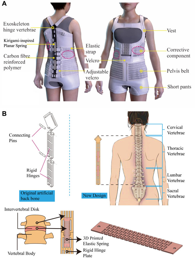
FIGURE 1. Exoskeleton hinge vertebrae design. (A) Overall design of exoskeleton hinge vertebrae. (B) Detailed design of hinge and kirigami-inspired spring structure.
The detailed structures of hinge vertebrae are presented in Figure 1B. The design was modified based on our previous work in Fok et al. (2022). As mentioned in the Introduction section, the previous design of the hinge bone only allowed the subject to bend along the sagittal plane and did not provide support in the sagittal plane during bending, which affected the durability and wearing comfort of the brace. Therefore, newly designed flexible brace with kirigami-inspired springs would provide assistive torque by changing from 2D structures to 3D structures to the spine, which can reduce the maximum stress point to control spinal deformity, allowing more flexible movement on the sagittal plane, and design to encourage the patients to stay in a good upright posture. In the new design, the hinge vertebrae put in the center back are used to sustain the counter force brought by the corrective pad and pelvis belt. It also limits trunk rotation but allows forward bending and considers less effect on the user’s mobility. The multisegment design of hinge vertebrae mimics the structure of the human spine. Kirigami-inspired springs are attached to the backside of rigid hinges to provide supportive torque during the subject’s flexion motion, which could reduce the stress concentrated on intervertebral discs and improve comfortability.
2.2 Kinematic description for hinge bending
The kinematic description of the elastic hinge is shown in Figure 2. The deformation ratio of the kirigami-inspired elastic spring will be determined in this section. There are two boundary deformation ratios: λmin and λmax. Though the actual deformation ratio of spring λ could not be determined kinematically for different materials and structures, it should be within these two boundary deformation ratios.
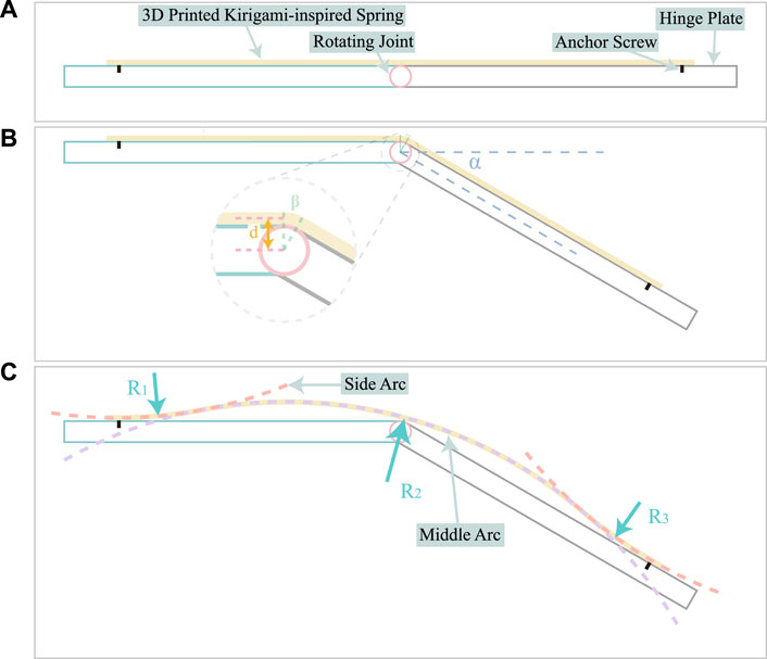
FIGURE 2. Kinematic description of kirigami-inspired elastic hinges. (A) Resting state of hinge; (B) Schematic diagram for smallest deformation ratio (α = 30°); (C) Schematic diagram for largest deformation ratio (α = 30°).
The schematic diagram for minimum deformation ratio λmin is shown in Figure 2B. In this scenario, the spring is firmly attached to the rigid plate. Set the original length (distance between two connections) of the kirigami-inspired spring to be L0, and we would have:
where d is the distance between the spring’s center line and the rigid plate’s center line; β is identical to the bending angle of hinge α.
The schematic diagram for maximum deformation ratio λmax is shown in Figure 2C, where three symmetrical arc segments combine with the deformed spring. The two side arcs are identical theoretically (i.e., R1 = R3) and tangent to the middle arc. The middle arc is tangent to the rotating joint, and the two side arcs are tangent to the rigid hinge plate. To calculate the arc radii (R1, R2) and their corresponding central angles (γ, δ), a schematic diagram was made by rotating Figure 2C counterclockwise along the rotating joint of hinge by α/2 angle and presented in Figure 3. Point O is the tangent point between middle arc and the rotating joint. Point D and G are the tangent points between side arcs and rigid hinge plates. To simplify the calculation, we have that
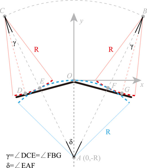
FIGURE 3. Schematic diagram for calculating the largest deformation ratio of the kirigami-inspired spring.
Assuming the kirigami-inspired spring is a uniform structure, the radius of side arc and middle arc should be identical. Set R1 = R2 = R. Build the Cartesian coordinate system, and set point O as the original point. The function of arc
From Eq.2, we have
The length of line
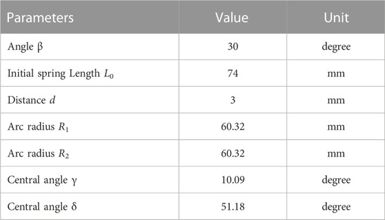
TABLE 1. Geometry parameters when the hinge bending angle α =30° for upper boundary deformation ratio λmax.
Based on Eqs 1, 5 and the parameters in Table 1, for spring deformation ratio λ we have that 2.12% < λ < 2.95%.
2.3 Design and fabrication of kirigami-inspired planar spring
The employed kirigami-inspired patterns and photos of planar springs are presented in Figure 4. Ribbon kirigami pattern Sun et al. (2021) is adopted in the spring design, which was first presented in improving the mechanical properties of graphene Qi et al. (2014). The elasticity of the rigid engineering parts could be improved by applying this simple geometry cutting pattern. By changing the geometry parameters, four patterns are developed. The ribbon width from Figures 4A–D varied between 1 mm and 3 mm. The kirigami patterns in Figure 4A is with two column structure and kirigami patterns shown in Figures 4B–D are with single column structure. The slit weight of kirigami patterns is uniformly designed to be 1 mm to prevent conglutination during fabrication. The kirigami-inspired spring is 3D printed (Ultimaker S5, Ultimaker Inc. Netherlands) with carbon-fiber reinforced nylon (PA-CF) material (PA-CF LOW WARP, Colorfabb, Netherlands). The optimized printing parameters are shown in Table 2. The buffering-by-buckling design allows the kirigami-inspired to extend the elongation property by transferring the linear deformation of spring to the bending of beams. Therefore, with the proper design, the material strain in the spring would be smaller than the overall elongation ratio. The finite element method (FEM) was employed during the spring design. The setup and results of FEM are illustrated in Section 2.4.3 and Section 3.1.1, respectively.
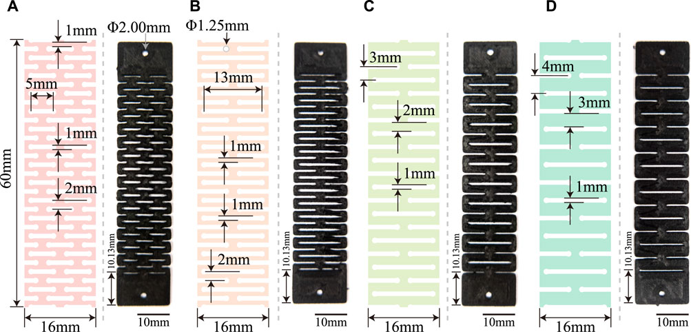
FIGURE 4. Kirigami-inspired patterns and photos of planar springs. (A) Double-Column-Flat-2mm pattern; (B) Single-Column-Flat-2mm pattern; (C) Single-Column-Flat-3mm pattern; (D) Single-Column-Flat-4mm pattern. Dimensions of the kirigami patterns are listed in the figure.
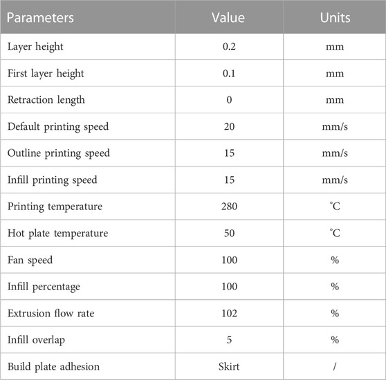
TABLE 2. Optimized 3D printing parameters for PA-CF.
2.4 Experiment setup to determine the mechanical properties of the kirigami-inspired spring and exoskeleton hinge
2.4.1 Spring stiffness test
The experiment setup for the spring stiffness test is shown in Figure 5. A pair of jigs fixed the kirigami-inspired springs. One jig was fixed, and another was connected to a moving stage. The samples would be stretched at 50 mm/min speed during the test until they break. The resistive forces generated by the spring are measured by a load cell (SBT673, Simbatouch, China), and the stretching distances are measured by a rope encoder (MPS-XS-1000, Miran, China). A DAQ device (USB6212, NI, USA) was employed to record the force and displacement signals.
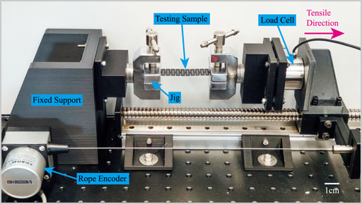
FIGURE 5. Experimental setup for spring stiffness testing.
2.4.2 Bending stiffness test
Figure 6 shows the experimental setup to measure the bending stiffness of the hinge vertebrae. The specimen was mounted on a customized torque measurement device. One plate of the hinge was fixed, and the rotational platform rotated another plate with the hinge joint with the elastomer. The rotational angle was measured by an encoder (MPS-XS-1000, Miran, China). The torque generated by the elastomer was measured by a torque sensor (SBT850, Simbatouch, China). The angle and torque were measured by a DAQ device (USB6212, NI, USA) at 1 kHz frequency. During the experiment, the elastic hinges were bent to maximum bending angle αmax (30°) with a bending velocity of 5°/s.
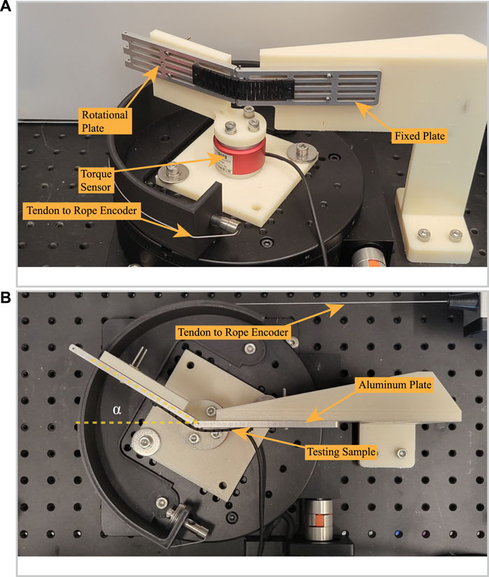
FIGURE 6. Experiment setup for measuring stiffness of exoskeleton hinge vertebrate. (A) Side view of the experiment setup at the initial state. (B) Top view of the experiment setup when the bending angle is 30°.
2.4.3 Finite element method (FEM) setup
The finite element method was employed during the design process to guarantee that the stresses on different kirigami configuration of springs made of PA-CF material could be lower than the material’s yield stress. The FEM was performed using Ansys Workbench R15.0 (Ansys, Inc. USA). ‘Static Structure’ block with ‘Linear Elastic’ material properties was applied. The properties of the PA-CF material are listed in Table 3. Young’s modulus was calculated based on the technical datasheet of the material colorFabb (2022). Ansys Workbench Software automatically generated the value of the bulk modulus and shear modulus. The mesh settings are presented in Table 4. The boundary conditions of FEM are shown in Figure 7. One end of the kirigami-inspired spring was fixed, while another end was stretched. The stretching displacement would be synchronized with the deformation at the break in benchtop testing (illustrated in Section 2.4.1). The stress and resistive force versus deformation ratio were determined.
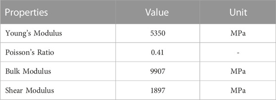
TABLE 3. Properties of PA-CF material.
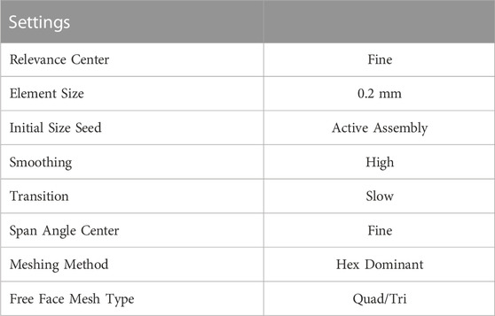
TABLE 4. Mesh settings for FEM.
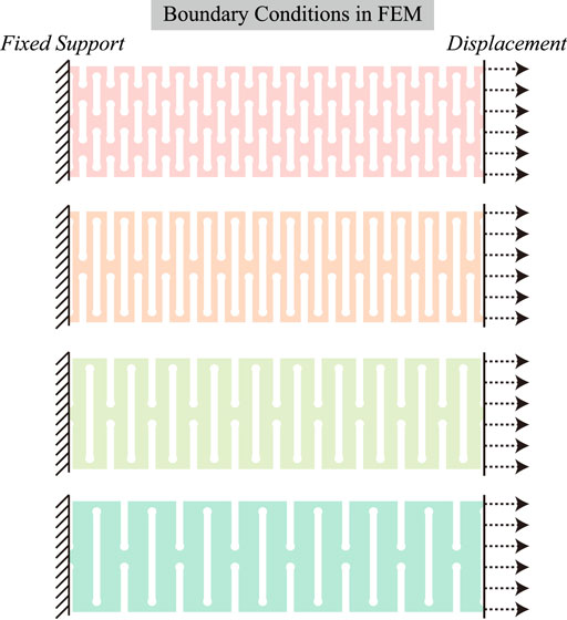
FIGURE 7. Schematic diagram to present experimental setup in FEM. Boundary conditions (fixed support and displacement) were indicated.
2.5 Preliminary human trial
2.5.1 Subject recruitment criteria
Female adolescents between 10–14 years old with moderate scoliosis (Cobb angle between 20–45°), classified as ≤ 2 under the Risser sign system and a BMI ≤25, were recruited to participate in the wear trial. Moreover, they should be able to adhere to the wear trial protocol physically and mentally and communicate in English or Chinese effectively. Subjects who had any spinal-related operation or had received bracing therapy or other spine therapies like scoliosis-specific exercise were excluded. This study was approved by the Human Subject Ethics Review Committee of The Hong Kong Polytechnic University (Reference Number: HSEARS20141220002).
2.5.2 Procedures of initial wear trial
Subjects with a 5° angle of trunk rotation (ATR), indicating the possibility of having an underlying scoliosis condition, were asked to perform a radiographic examination before the initial wear trial to verify the Risser sign and the spinal curvature. The initial wear trial mainly evaluated the 2-h intervention effect in correcting spinal curvature by the flexible brace with the exoskeleton hinge vertebrae. Liu et al. (2015). Negrini et al. Negrini et al. (2012) recommended using an in-brace x-ray as one of the metrics to evaluate the efficacy of the brace treatment. Therefore, the before and after radiographs, out-brace or in-brace of each subject are obtained to evaluate prior and current changes in the brace treatment. The hinge is made of carbon fiber-reinforced polymer with kirigami-patterned elastomer. The radiographs were taken before and after a 2-h intervention with the brace donned to compare the in-orthosis correction result; a standing posture in the radiographic examination is required Katz and Durrani (2001). The equation of change in spinal curvature is calculated as:
A positive and negative number indicates an increase and reduction in spinal curvature.
3 Results
3.1 Mechanical properties of kirigami-inspired spring
3.1.1 Stiffness of kirigami-inspired spring and FEM results
The tensile test and finite element method (FEM) analysis results of the kirigami-inspired spring are shown in Figure 8. Four testing samples for each kirigami pattern were stretched until they were broken. The averaged force testing data for each kirigami patterns with error bars were presented. The photos of broken samples are shown in Figure 9. As mentioned in Section 2.4.3, the stretching deformation ratios in FEM were identical to the deformation ratios at the break in the tensile test. The estimated tensile force in FEM analysis and the measured experimental data were plotted in dashed blue and solid red lines, respectively. The stiffness k of the kirigami samples were calculated based on the force and displacement value at the theoretical maximum deformation when the spring installed on the exoskeleton hinge. That is
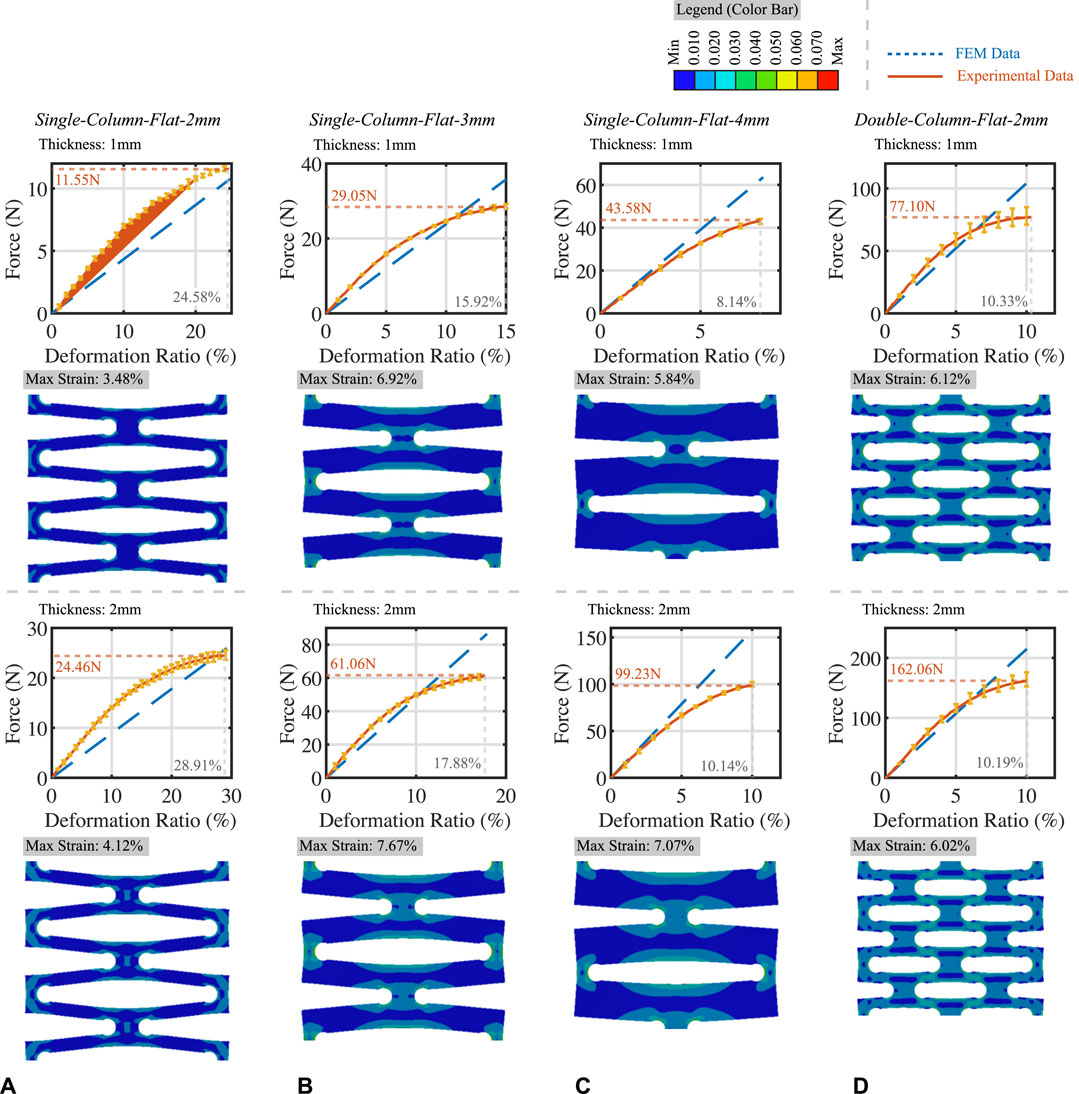
FIGURE 8. Tensile test and FEM results of kirigami-inspired springs. (A) Results of spring with Single-Column-Flat-2mm pattern; (B) Results of spring with Single-Column-Flat-3mm pattern; (C) Results of spring with Single-Column-Flat-4mm pattern; (D) Results of spring with Double-Column-Flat-2mm pattern.
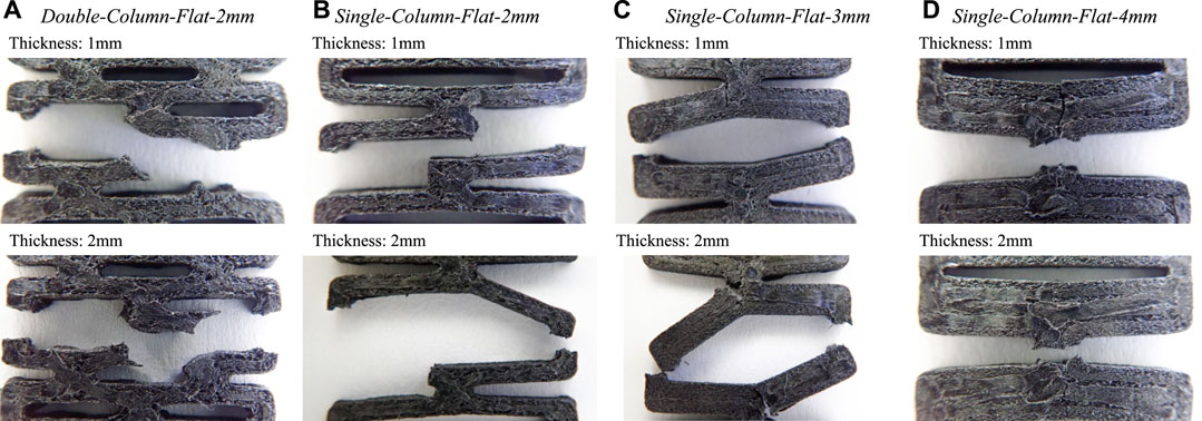
FIGURE 9. Close-up photos of cracked kirigami-inspired springs in tensile test with different patterns and thicknesses. (A) Double-Column-Flat-2mm pattern; (B) Single-Column-Flat-2mm pattern; (C) Single-Column-Flat-3mm pattern; (D) Single-Column-Flat-4mm pattern.
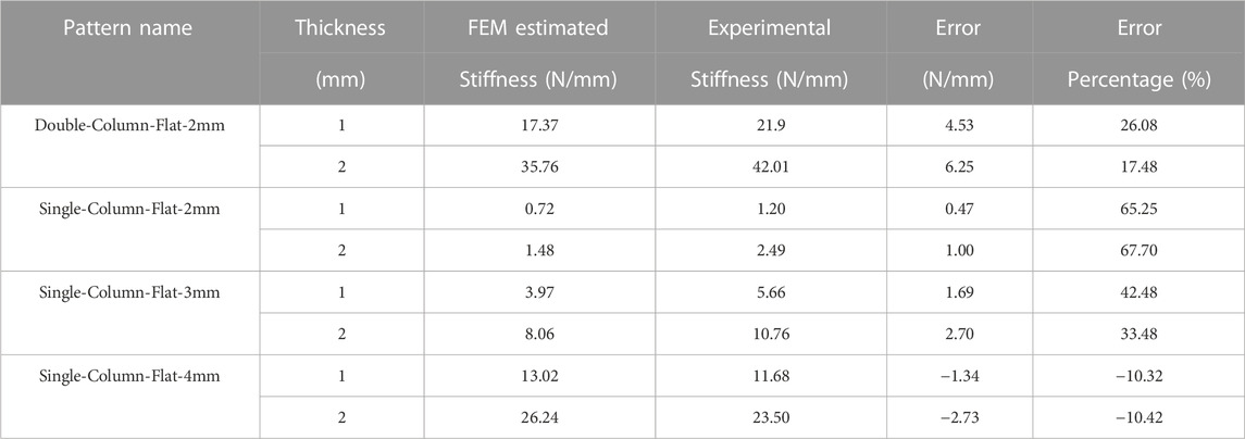
TABLE 5. Comparison between FEM estimated stiffness and experimental stiffness of kirigami samples with error and error percentage.
3.1.2 Resistive torque of exoskeleton hinge
The bending stiffness test results are illustrated in Figure 10. Arrows indicate the bending directions. The maximum torque during bending was recorded in the figure. The average bending stiffness of the kirigami-inspired elastic hinge was calculated by dividing the maximum bending torque by the maximum bending angles. The calculation results are presented in Table 6. The stiffness of elastic hinge with 1-mm thick kirigami-inspired springs varied between 0.67 mNm/degree and 4.97 Nm/degree, while the stiffness of elastic hinge with 2-mm thick kirigami-inspired springs varied between 1.47 mNm/degree and 10.37 Nm/degree. A comparison between human invertebrate stiffness and our kirigami-inspired elastic hinge is illustrated in Section 4. The energy absorption of kirigami-inspired springs was also determined by calculating the gap area (pink region) between bending and relaxing in Figure 10. The calculated values of absorbed energy were presented below the torque responses plot.
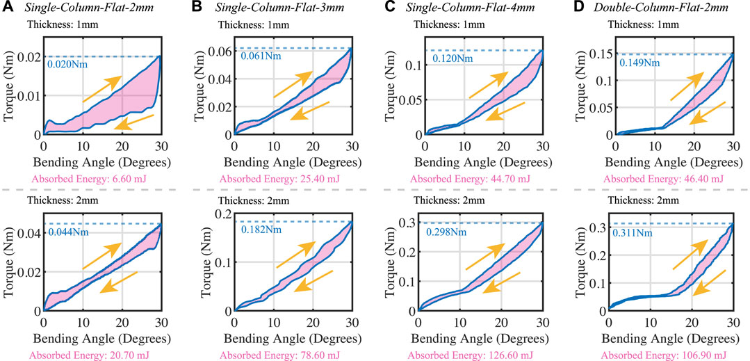
FIGURE 10. Bending stiffness test results of different kirigami-inspired springs (A) Single-Column-Flat-2mm pattern; (B) Single-Column-Flat-3mm pattern; (C) Single-Column-Flat-4mm pattern; (D) Double-Column-Flat-2mm pattern. Energy absorption of each kirigami-inspired springs during the bending cycles are indicated with the pink regions.
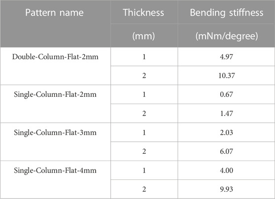
TABLE 6. Experimental bending stiffness of exoskeleton hinge vertebrae with different kirigami-inpsired springs.
3.2 Initial wear trial results
In this study, three subjects who fulfilled the inclusion criteria were asked to participate in the 2-h wear trial to evaluate the instant effect on the change of the spinal curvature of the flexible brace with the exoskeleton hinge vertebrae after a 2-h intervention. The clinical trial experiment is based on the previous paper using flexible brace to see the effect of the design with five subjects Fok et al. (2022). The X-ray images of subjects before and after the intervention are shown in Figure 11. According to Coillard et al. Coillard et al. (2007), in 2007, a brace treatment would be defined to have a positive outcome if there is an improvement of more than 5° in Cobb angle, while deterioration of more than 5° would be defined as having a negative outcome. Table 7 summarizes all immediate effects of the change of the Cobb angle after a 2-h brace intervention. All subjects in this wear trial demonstrated a positive effect in improving their primary curve. The most significant improvement was demonstrated in ATB002, who reduced her spinal curvature by 50.5%; her thoracolumbar curve was reduced from 20.6° to 10.2°. ATB001 and ATB003 have also reduced 27.2% (9.4°) and 27.4% (7.7°), respectively. All subjects have had a positive outcome on their spinal curvature. Compared to a 15.9% corrective effectiveness in a rigid brace and 21.3% in SpinCor (flexible brace), the corrective result in this wear trial is comparable with the traditional brace Guo et al. (2014).
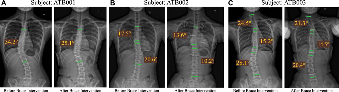
FIGURE 11. X-rays images of three subjects (A) subject ATB001 (B) subject ATB002 (C) subject ATB003 before and after a 2-h intervention. Green bars are indicated in the figure to measure Cobb angles.
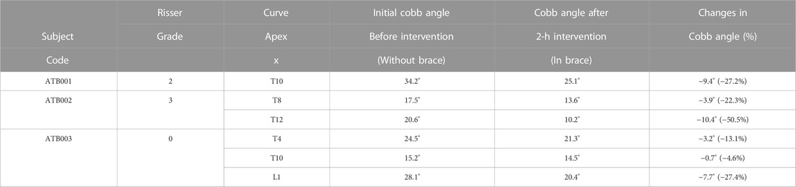
TABLE 7. Immediate effects in the change of the Cobb angle after a 2-h brace intervention.
4 Discussion
4.1 Stiffness of kirigami-inspired elastic hinge
By changing the kirigami patterns, the kirigami-inspired spring’s stiffness would change, resulting in a change in elastic hinge stiffness. Although it is not practical to build analytical stiffness models for every kirigami pattern due to its complex geometry, there is a rough relationship between patterns and spring stiffness. Based on the data in Tables 5 and Table 6 The stiffness of spring with the Double-Column-Flat pattern would be much larger than the stiffness of spring with the Single-Column-Flat pattern when the distances between cutting edges and spring thickness are identical. When the distance between cutting edges increased, the stiffness of the spring would also be increased.
4.2 Selection of materials of kirigami-inspired spring
During the design process, a batch of materials for kirigami-inspired springs, including metals (stainless steel, brass, etc.) and polymers (ABS, Nylon, PC, etc.) were nominated. However, the operating environments of the vertebrae exoskeleton bring some requirements to the kirigami-inspired elastic hinge.
1. The spring should be MRI-compatible. The vertebrae exoskeleton would be potentially used in MRI tests for patient assessment.
2. The tensile modulus (Young’s modulus) should be significantly large to ensure sufficient torque generation with a thin spring.
3. The spring should be made from a durable material.Considering the three points, the carbon fiber-reinforced nylon material was selected as the material of the kirigami-inspired spring, which is MRI-compatible and has large tensile modules thanks to the embedded carbon fibers.
During the evaluation process, a 1-mm thick ABS (Ultimaker, Netherlands) printed kirigami-inspired spring with the Single-Column-Flat-4mm pattern was tested with both a bending stiffness test and endurance test. The experiment results are shown in Figure 12. From the endurance test results, the spring would yield after 314 times of bending and break after 817 times of bending, which might not be durable when being used in activities of daily living (ADL).
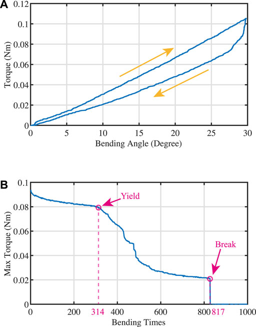
FIGURE 12. Experiment results of 1-mm thick ABS printed kirigami-inspired spring with pattern Single-Column-Flat-4mm. (A) Bending stiffness test results; (B) Endurance test results.
The bending stiffness of four 1-mm thick nylon (Ultimaker, Netherlands) printed kirigami-inspired springs with different kirigami patterns were also tested. The testing results are presented in Figure 13. From this figure, it could be observed that there is significant hysteresis on the torque during hinge bending, which would reduce the supporting effects of the vertebra exoskeleton during the backward bending process. Compared with PA-CF material, the comparatively small tensile modulus makes the nylon spring unable to generate sufficient assistive torque with a thin structure, which is also why we eliminated the TPU material (lower tensile modulus than Nylon material) as the spring material.
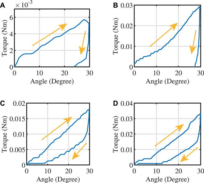
FIGURE 13. Bending stiffness test results of kirigami-inspired springs printed with Nylon material. (A) Results of spring with Single-Column-Flat-2mm pattern; (B) Results of spring with Single-Column-Flat-3mm pattern; (C) Results of spring with Single-Column-Flat-4mm pattern; (D) Results of spring with Double-Column-Flat-2mm pattern.
4.3 Supporting effects of kirigami-inspired elastic hinge
As mentioned in Section 2.1, the kirigami-inspired elastic hinge would provide a supportive torque during the flexion motion of subjects. The hinge’s supporting effects will be evaluated in this section by comparing it with the torque generated by human intervertebral discs. The stiffness of the human intervertebral disc was discussed in Somovilla Gómez et al. (2017); Guan et al. (2007); Busscher et al. (2010); Patwardhan et al. (2003); González Gutiérrez (2012) and varies between 0.8 and 1.18 Nm/° in flexion motion direction and 0.8 to 1.53 Nm/° in extension motion direction Somovilla Gómez et al. (2017). The difference in testing methods caused the variance in the stiffness value. Here we selected the value 1.18 Nm/° in González Gutiérrez (2012) as the intervertebral disc stiffness for comparison. The vertebra exoskeleton we designed could cover the thoracic vertebrae (T1 to T12) and lumbar vertebrae. There are sixteen in-between intervertebral discs. For simplicity, we assume the bending angles of each intervertebral disc are identical. Therefore, the relationship between the bending angles of the elastic hinge α and the bending angles of each intervertebral disc ψ can be expressed as:
where n is the number of elastic hinges in one vertebrae’s exoskeleton. In the current design, we have n = 2 and thus ψ = α/8. With the experiment data in Table 6, we determined that during bending, the kirigami-inspired elastic hinge could provide 0.45%–7.03% of supportive torque provided by intervertebral discs. The supporting effects of elastic hinges with each kirigami pattern are presented in Table 8. If the assistive support is from 1% to 5%, our subjects could feel the system reminding them to maintain an upright correct posture. At the same time, the user would not rely on the assistive torque, which might weaken their back extensor muscles. In our design, the kirigami-inspired springs with Double-Cloumn-Flat-2mm pattern, Single-Column-Flat-3mm pattern, and Single-Column-Flat-4mm pattern are recommended since they could provide appropriate assistive toque with unobtrusive size, which is conducive to our exoskeleton seamlessly integrating into patients’ daily life. The selection of assistive torque could be easily adjusted in the kirigami pattern, and it could be specifically designed based on the demand from subjects and their doctors.
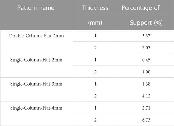
TABLE 8. Percentage of torque generated by intervertebral disc in flexion motion.
5 Conclusion
This paper presented a novel kirigami-inspired exoskeleton hinge vertebrae using the carbon-fiber-reinforced nylon material. Applying the kirigami-inspired structure lowered its internal stress during bending, facilitated the subject back to an upright posture easier, and maintained a better posture correction with the brace. The mechanical properties of kirigami-inspired springs with different configurations were analyzed and compared. A clinical trial was performed with the evaluation of immediate correction effects. The kirigami-inspired design reduced the thickness of the overall structure. The adjustable support design provides the feasibility of customization and encourages the subjects to maintain an upright posture to have better corrections to the spine curvature. At the same time, it provides support when bending forward and sitting down. The high lateral stiffness of the exoskeleton maintains the lateral corrective force and stabilizes the panels with the corrective force of the brace. This paper is a feasibility study to evaluate the new design with the kirigami structure. In further study, more subjects will be recruited to evaluate the effectiveness of the design.
Data availability statement
The original contributions presented in the study are included in the article/Supplementary material, further inquiries can be directed to the corresponding authors.
Ethics statement
The studies involving human participants were reviewed and approved by the Human Subject Ethics Review Committee of The Hong Kong Polytechnic University (Reference Number: HSEARS20141220002). Written informed consent to participate in this study was provided by the participants’ legal guardian/next of kin.
Author contributions
QL, JS, JW, JY, and RT contributed to conception and design of the study. WFW fabricated the kirigami-inspired springs. JS, JW, SL, and RT tested the mechanical properties of kirigami-inspired springs. QL, HC, JC, and JY tested the effects of exoskeleton on human subject. QL, JS, JW, JY, and RT wrote the manuscript. All authors contributed to manuscript revision, read, and approved the submitted version.
Funding
This study is co-funded by the Innovation and Technology Fund, HKSAR (Ref. No. ITS/156/20FP), Lee Hysan Foundation (Ref. No. R-ZH3Y) and the Laboratory for Artificial Intelligence in Design under the InnoHK Research Clusters, HKSAR (Ref. No. RP1-4).
Conflict of interest
The authors declare that the research was conducted in the absence of any commercial or financial relationships that could be construed as a potential conflict of interest.
Publisher’s note
All claims expressed in this article are solely those of the authors and do not necessarily represent those of their affiliated organizations, or those of the publisher, the editors and the reviewers. Any product that may be evaluated in this article, or claim that may be made by its manufacturer, is not guaranteed or endorsed by the publisher.
References
Ali, A., Fontanari, V., Schmoelz, W., and Agrawal, S. K. (2021). Systematic review of back-support exoskeletons and soft robotic suits. Front. Bioeng. Biotechnol. 9, 765257. doi:10.3389/fbioe.2021.765257
Bertoldi, K., Reis, P. M., Willshaw, S., and Mullin, T. (2010). Negative Poisson’s ratio behavior induced by an elastic instability. Adv. Mater. 22, 361–366. doi:10.1002/adma.200901956
Bobbert, F., Janbaz, S., van Manen, T., Li, Y., and Zadpoor, A. (2020). Russian doll deployable meta-implants: Fusion of kirigami, origami, and multi-stability. Mater. Des. 191, 108624. doi:10.1016/j.matdes.2020.108624
Busscher, I., van der Veen, A. J., van Dieën, J. H., Kingma, I., Verkerke, G. J., and Veldhuizen, A. G. (2010). In vitro biomechanical characteristics of the spine: A comparison between human and porcine spinal segments. Spine 35, E35–E42. doi:10.1097/brs.0b013e3181b21885
Cai, J., and Akbarzadeh, A. (2021). Hierarchical kirigami-inspired graphene and carbon nanotube metamaterials: Tunability of thermo-mechanic properties. Mater. Des. 206, 109811. doi:10.1016/j.matdes.2021.109811
Chan, W.-Y., Yip, J., Yick, K.-L., Ng, S.-P., Lu, L., Cheung, K. M.-C., et al. (2018). Mechanical and clinical evaluation of a shape memory alloy and conventional struts in a flexible scoliotic brace. Ann. Biomed. Eng. 46, 1194–1205. doi:10.1007/s10439-018-2016-8
Chen, S., Chan, K., Han, D., Zhao, L., and Wu, F. (2019). Programmable super elastic kirigami metallic glasses. Mater. Des. 169, 107687. doi:10.1016/j.matdes.2019.107687
Cheng, Y.-C., Lu, H.-C., Lee, X., Zeng, H., and Priimagi, A. (2020). Kirigami-based light-induced shape-morphing and locomotion. Adv. Mater. 32, 1906233. doi:10.1002/adma.201906233
Coillard, C., Circo, A., and Rivard, C. (2014). A prospective randomized controlled trial of the natural history of idiopathic scoliosis versus treatment with the SpineCor brace. Sosort Award 2011 winner. Eur. J. Phys. Rehabil. Med. 50, 479–487.
Coillard, C., Vachon, V., Circo, A. B., Beauséjour, M., and Rivard, C. H. (2007). Effectiveness of the spinecor brace based on the new standardized criteria proposed by the scoliosis research society for adolescent idiopathic scoliosis. J. Pediatr. Orthop. 27, 375–379. doi:10.1097/01.bpb.0000271330.64234.db
ColorFabb, (2022). Pa-cf low warp. Available at: https://colorfabb.com/pa-cf-low-warp.
Costa, L., Schlosser, T. P., Jimale, H., Homans, J. F., Kruyt, M. C., and Castelein, R. M. (2021). The effectiveness of different concepts of bracing in adolescent idiopathic scoliosis (ais): A systematic review and meta-analysis. J. Clin. Med. 10, 2145. doi:10.3390/jcm10102145
Eda, A., Yasuga, H., Sato, T., Sato, Y., Suto, K., Tachi, T., et al. (2022). Large curvature self-folding method of a thick metal layer for hinged origami/kirigami stretchable electronic devices. Micromachines 13, 907. doi:10.3390/mi13060907
Firouzeh, A., Higashisaka, T., Nagato, K., Cho, K., and Paik, J. (2020). Stretchable kirigami components for composite meso-scale robots. IEEE Robotics Automation Lett. 5, 1883–1890. doi:10.1109/lra.2020.2969924
Fok, Q., Yip, J., Yick, K.-l., and Ng, S.-p. (2022). Design and fabrication of anisotropic textile brace for exerting corrective forces on spinal curvature. J. Industrial Text. 51, 1682S–1702S. doi:10.1177/15280837211032619
Gao, B., Elbaz, A., He, Z., Xie, Z., Xu, H., Liu, S., et al. (2018). Bioinspired kirigami fish-based highly stretched wearable biosensor for human biochemical–physiological hybrid monitoring. Adv. Mater. Technol. 3, 1700308. doi:10.1002/admt.201700308
González Gutiérrez, R. A. (2012). Biomechanical study of intervertebral disc degeneration. Spain: Universitat Politècnica de Catalunya (Ph.D. thesis.
Guan, Y., Yoganandan, N., Moore, J., Pintar, F. A., Zhang, J., Maiman, D. J., et al. (2007). Moment–rotation responses of the human lumbosacral spinal column. J. biomechanics 40, 1975–1980. doi:10.1016/j.jbiomech.2006.09.027
Guo, J., Lam, T. P., Wong, M. S., Ng, B. K. W., Lee, K. M., Liu, K. L., et al. (2014). A prospective randomized controlled study on the treatment outcome of spinecor brace versus rigid brace for adolescent idiopathic scoliosis with follow-up according to the srs standardized criteria. Eur. Spine J. 23, 2650–2657. doi:10.1007/s00586-013-3146-1
Hart, G. W. (2007). “Modular kirigami,” in Bridges donostia: Mathematics, music, art, architecture, culture (United States: The Bridges Organization).
Hresko, M. T. (2013). Idiopathic scoliosis in adolescents. N. Engl. J. Med. 368, 834–841. doi:10.1056/nejmcp1209063
Katz, D. E., and Durrani, A. (2001). Factors that influence outcome in bracing large curves in patients with adolescent idiopathic scoliosis. Spine 26, 2354–2361. doi:10.1097/00007632-200111010-00012
Konieczny, M. R., Senyurt, H., and Krauspe, R. (2013). Epidemiology of adolescent idiopathic scoliosis. J. children’s Orthop. 7, 3–9. doi:10.1007/s11832-012-0457-4
Lamoureux, A., Lee, K., Shlian, M., Forrest, S. R., and Shtein, M. (2015). Dynamic kirigami structures for integrated solar tracking. Nat. Commun. 6, 8092–8096. doi:10.1038/ncomms9092
Law, D., Cheung, M.-c., Yip, J., Yick, K.-L., and Wong, C. (2017). Scoliosis brace design: Influence of visual aesthetics on user acceptance and compliance. Ergonomics 60, 876–886. doi:10.1080/00140139.2016.1227093
Liu, P.-Y., Yip, J., Yick, K.-L., Yuen, C.-W. M., Tse, C.-Y., Ng, S.-P., et al. (2015). Effects of a tailor-made girdle on posture of adolescents with early scoliosis. Text. Res. J. 85, 1234–1246. doi:10.1177/0040517514561928
Ma, J., Dai, H., Chai, S., and Chen, Y. (2021). Energy absorption of sandwich structures with a kirigami-inspired pyramid foldcore under quasi-static compression and shear. Mater. Des. 206, 109808. doi:10.1016/j.matdes.2021.109808
Ming, S., Song, Z., Li, T., Du, K., Zhou, C., and Wang, B. (2020). The energy absorption of thin-walled tubes designed by origami approach applied to the ends. Mater. Des. 192, 108725. doi:10.1016/j.matdes.2020.108725
Näf, M. B., Koopman, A. S., Baltrusch, S., Rodriguez-Guerrero, C., Vanderborght, B., and Lefeber, D. (2018). Passive back support exoskeleton improves range of motion using flexible beams. Front. Robotics AI 5, 72. doi:10.3389/frobt.2018.00072
Nakajima, J., Fayazbakhsh, K., and Teshima, Y. (2020). Experimental study on tensile properties of 3d printed flexible kirigami specimens. Addit. Manuf. 32, 101100. doi:10.1016/j.addma.2020.101100
Negrini, S., Aulisa, A. G., Aulisa, L., Circo, A. B., De Mauroy, J. C., Durmala, J., et al. (2012). 2011 sosort guidelines: Orthopaedic and rehabilitation treatment of idiopathic scoliosis during growth. Scoliosis 7, 3–35. doi:10.1186/1748-7161-7-3
Niknam, H., Sarvestani, H. Y., Jakubinek, M., Ashrafi, B., and Akbarzadeh, A. (2020). 3d printed accordion-like materials: A design route to achieve ultrastretchability. Addit. Manuf. 34, 101215. doi:10.1016/j.addma.2020.101215
Ning, X., Wang, X., Zhang, Y., Yu, X., Choi, D., Zheng, N., et al. (2018). Assembly of advanced materials into 3d functional structures by methods inspired by origami and kirigami: A review. Adv. Mater. Interfaces 5, 1800284. doi:10.1002/admi.201800284
Patwardhan, A. G., Havey, R. M., Carandang, G., Simonds, J., Voronov, L. I., Ghanayem, A. J., et al. (2003). Effect of compressive follower preload on the flexion–extension response of the human lumbar spine. J. Orthop. Res. 21, 540–546. doi:10.1016/s0736-0266(02)00202-4
Qi, Z., Campbell, D. K., and Park, H. S. (2014). Atomistic simulations of tension-induced large deformation and stretchability in graphene kirigami. Phys. Rev. B 90, 245437. doi:10.1103/physrevb.90.245437
Rafsanjani, A., Zhang, Y., Liu, B., Rubinstein, S. M., and Bertoldi, K. (2018). Kirigami skins make a simple soft actuator crawl. Sci. Robotics 3, eaar7555. doi:10.1126/scirobotics.aar7555
Sedal, A., Memar, A. H., Liu, T., Mengüç, Y., and Corson, N. (2020). Design of deployable soft robots through plastic deformation of kirigami structures. IEEE Robotics Automation Lett. 5, 2272–2279. doi:10.1109/lra.2020.2970943
Shu, J., Wang, J., Su, Y., Liu, H., Li, Z., and Tong, R. K.-y. (2022). “An end-to-end posture perception method for soft bending actuators based on kirigami-inspired piezoresistive sensors,” in Proceeding of the 2022 IEEE-EMBS International Conference on Wearable and Implantable Body Sensor Networks, Ioannina, Greece, 27-30 Sept. 2022 (IEEE).
Somovilla Gómez, F., Lostado Lorza, R., Corral Bobadilla, M., and Escribano García, R. (2017). Improving the process of adjusting the parameters of finite element models of healthy human intervertebral discs by the multi-response surface method. Materials 10, 1116. doi:10.3390/ma10101116
Sun, Y., Ye, W., Chen, Y., Fan, W., Feng, J., and Sareh, P. (2021). Geometric design classification of kirigami-inspired metastructures and metamaterials. Structures 33, 3633–3643. doi:10.1016/j.istruc.2021.06.072
Suzuki, H., and Wood, R. J. (2020). Origami-inspired miniature manipulator for teleoperated microsurgery. Nat. Mach. Intell. 2, 437–446. doi:10.1038/s42256-020-0203-4
Toxiri, S., Calanca, A., Poliero, T., Caldwell, D. G., and Ortiz, J. (2018a). “Actuation requirements for assistive exoskeletons: Exploiting knowledge of task dynamics,” in International symposium on wearable robotics (Germany: Springer), 381–385.
Toxiri, S., Koopman, A. S., Lazzaroni, M., Ortiz, J., Power, V., De Looze, M. P., et al. (2018b). Rationale, implementation and evaluation of assistive strategies for an active back-support exoskeleton. Front. Robotics AI 5, 53. doi:10.3389/frobt.2018.00053
Toxiri, S., Näf, M. B., Lazzaroni, M., Fernández, J., Sposito, M., Poliero, T., et al. (2019). Back-support exoskeletons for occupational use: An overview of technological advances and trends. IISE Trans. Occup. Ergonomics Hum. Factors 7, 237–249. doi:10.1080/24725838.2019.1626303
Vella, D. (2019). Buffering by buckling as a route for elastic deformation. Nat. Rev. Phys. 1, 425–436. doi:10.1038/s42254-019-0063-1
Wang, H., Xiao, S., and Wang, J. (2021). Disordered auxetic metamaterials architected by random peanut-shaped perturbations. Mater. Des. 212, 110291. doi:10.1016/j.matdes.2021.110291
Weinstein, S. L., Dolan, L. A., Wright, J. G., and Dobbs, M. B. (2013). Effects of bracing in adolescents with idiopathic scoliosis. N. Engl. J. Med. 369, 1512–1521. doi:10.1056/nejmoa1307337
Weiss, H.-R., Karavidas, N., Moramarco, M., and Moramarco, K. (2016). Long-term effects of untreated adolescent idiopathic scoliosis: A review of the literature. Asian Spine J. 10, 1163. doi:10.4184/asj.2016.10.6.1163
Wong, C. S.-h., Yip, J., Yick, K.-l., and Ng, Z. S.-p. (2021). “A case study of initial in-brace spinal correction of anisotropic textile brace and boston brace,” in International conference on applied human factors and ergonomics (Germany: Springer), 109–115.
Wong, M. S., Mak, A., Luk, K., Evans, J., and Brown, B. (2000). Effectiveness and biomechanics of spinal orthoses in the treatment of adolescent idiopathic scoliosis (ais). Prosthetics Orthot. Int. 24, 148–162. doi:10.1080/03093640008726538
Yang, C., Zhang, H., Liu, Y., Yu, Z., Wei, X., and Hu, Y. (2018). Kirigami-inspired deformable 3d structures conformable to curved biological surface. Adv. Sci. 5, 1801070. doi:10.1002/advs.201801070
Yang, D., Wang, H., Luo, S., Wang, C., Zhang, S., and Guo, S. (2019). Paper-cut flexible multifunctional electronics using MoS2 nanosheet. Nanomaterials 9, 922. doi:10.3390/nano9070922
Yang, X., Huang, T.-H., Hu, H., Yu, S., Zhang, S., Zhou, X., et al. (2019). Spine-inspired continuum soft exoskeleton for stoop lifting assistance. IEEE Robotics Automation Lett. 4, 4547–4554. doi:10.1109/lra.2019.2935351
Yu, H. C., Hao, X. P., Zhang, C. W., Zheng, S. Y., Du, M., Liang, S., et al. (2021). Engineering tough metallosupramolecular hydrogel films with kirigami structures for compliant soft electronics. Small 17, 2103836. doi:10.1002/smll.202103836
Keywords: 3D printing, kirigami, finite element methods, scoliosis, brace
Citation: Lei QE, Shu J, Wang J, Cheung HY, Cheung JPY, Wong WF, Lau SCY, Yip J and Tong RKY (2023) Design and characterize of kirigami-inspired springs and the application in vertebrae exoskeleton for adolescent idiopathic scoliosis brace treatment. Front. Mech. Eng 9:1152930. doi: 10.3389/fmech.2023.1152930
Received: 28 January 2023; Accepted: 03 March 2023;
Published: 22 March 2023.
Edited by:
Alessandro Ruggiero, University of Salerno, ItalyReviewed by:
Nicola Cappetti, University of Salerno, ItalyYongtao Lu, Dalian University of Technology (DUT), China
Copyright © 2023 Lei, Shu, Wang, Cheung, Cheung, Wong, Lau, Yip and Tong. This is an open-access article distributed under the terms of the Creative Commons Attribution License (CC BY). The use, distribution or reproduction in other forums is permitted, provided the original author(s) and the copyright owner(s) are credited and that the original publication in this journal is cited, in accordance with accepted academic practice. No use, distribution or reproduction is permitted which does not comply with these terms.
*Correspondence: Joanne Yip, am9hbm5lLnlpcEBwb2x5dS5lZHUuaGs=; Raymond K. Y. Tong, a3l0b25nQGN1aGsuZWR1Lmhr
†These authors have contributed equally to this work and share first authorship