Abstract
Introduction: As the increase in electrification poses new demands on power delivery, the quality of the distribution system is paramount. Substations are a critical part of power grids that allow for control and service of the electrical distribution system. Substations are currently developed in a project-based and manually intensive manner, with a high degree of manual work and lengthy lead times. Substations are primarily sold through tenders that are accompanied by an inherent need for engineering-to-order activities. Although necessary, these activities present a paradox as tender processes must be agile and fast. To remedy this shortcoming, this article outlines a knowledge capture and reuse methodology to standardize and automate the product development processes of substation design.
Methods: A novel framework for substation design is presented that implements knowledge-based engineering (KBE) and artificial intelligence methods in computer vision to capture knowledge. In addition, a product configuration system is presented, utilizing high-level CAD templates. The development has followed the KBE methodology MOKA.
Results: The proposed framework has been implemented on several company cases where three (simplified) are presented in this paper. The framework decreased the time to create a 3D model from a basic electric single line diagram by performing the identification and design tasks in an automated fashion.
Discussion: Ultimately, the framework will allow substation design companies to increase competitiveness through automation and knowledge management and enable more tenders to be answered without losing engineering quality.
1 Introduction
Access to quality electricity is essential for a modern society. Power distribution networks have been and are still being built to ensure ample electricity supply. The power distribution grid is made of many parts from power generation to power consumption. Substations are essential power grid components that distribute power from the main grid to regional grids, factories, residential areas, etc. Substations vary in size and appearance depending on their environment. However, the design process for a substation is generally the same, irrespective of the location or scale it is designed for. To accommodate customer requirements, companies adopt a strategy known as mass customization, a rapidly growing manufacturing and product design strategy (Elgh and Johansson, 2020). To stay competitive and flexible in a mass customization effort, many manufacturers seek to incorporate design automation (DA), product configuration systems (PCSs), and knowledge-based engineering (KBE) in their design process for fast and cost-efficient tendering (Willner et al., 2016; Elgh and Johansson, 2020). Despite this, substations are generally treated as new projects rather than a configurable product (Nordvall and Rydebrink, 2021). The engineering process is project-based as well as engineering to order (ETO) (Willner et al., 2016). While it is true that ETO solutions are inherently resource-intensive, they provide companies with the flexibility to remain agile and respond quickly to shifting market demands (Grabenstetter and Usher, 2014).
In a review of product configurators conducted by Zhang (2014), fourteen areas of product configuration issues in research were established. Many of the areas outlined by Zhang are closely related to mass customization and ETO strategies. Currently, research is conducted in the ETO field but research on the digitalization of ETO companies is limited (Thun et al., 2022). Template matching research is often theoretical, focusing on the methodology such as in Han (2021). Applications are related to imaging and knowledge capture (Cheng and Han, 2016). The design process of substation layout in the distribution grid is researched in Zhou et al. (2018) and digital tools for substation design and visualization in Carvalho et al. (2016).
Knowledge capture methods and the importance of data are increasingly vital for companies to stay competitive. In addition, the emergence of digital twins illustrates a new need for digital representations of physical products and systems such as substations. Despite a wealth of research on substation design, there is still a critical gap in knowledge: how to automatically translate a single-line diagram (SLD) into a comprehensive 3D model, complete with a bill of materials (BOM) and 2D drawings. The SLD serves as a functional representation of the electrical circuits within the proposed substation, while the BOM provides a detailed list of all the system components, allowing for cost calculation and effective planning during the building phase.
In the context of substation development, productivity and agility are two critical factors for success. This article proposes a novel solution in the form of a design automation framework based on DA principles. By using high-level CAD templates and template matching, this framework allows for the seamless integration of multiple substation development phases, resulting in increased productivity without sacrificing agility. The methodology for knowledge-based engineering applications (MOKA) was used for development. MOKA is a systematic approach for collecting and organizing engineering knowledge to create reusable DA solutions (Stokes, 2001).
The core of the proposed framework is a digital twin that incorporates electric functionality and a 3D representation of the substation design. Specifically, the framework can generate a 3D model of a high voltage substation automatically from an SLD, offering a powerful tool for efficient and effective substation development.
1.1 Application background
The need for applications of KBE methods using DA and PCSs is present in the application context of substation tenders. Engineers and managers believe that 40% of the tender time could be reduced by standardizing and removing repetitive processes. Furthermore, standardized components and suppliers would decrease the realized cost for the detail design at a later stage. The potential for a tender design that is more thoroughly developed can reduce the detail design time, resulting in a better product.
Businesses in this area typically start with a tender process where companies compete against each other to win the deal. The typical tender process varies between 4 and 14 weeks, depending on the complexity of the substation. Approximately half the time is spent on engineering design activities (Nordvall and Rydebrink, 2021).
Mapping of the current process was carried out by interviews with managers and engineers, study of technical documentation of old substations, and literature study (Nordvall and Rydebrink, 2021). Substation design activities were compiled into five steps, shown in Figure 1 the design steps are also in line with the suggested design activities from McDonald (2021). The interviews were held in a pre-study to outline the current process and design activities. After the pre-study, directed interviews and workshops were held with mechanical and electrical engineers.
FIGURE 1

Flowchart representing the activities of the current tender process.
Previous substation design projects were provided by the company for scrutiny. SLDs provided by customers or designed in-house were studied together with finished station drawings to map out symbols and SLD data and what equipment they represent in 3D space.
Substation types vary depending on their purpose. The most common type of station is a distribution station. These are located close to cities and neighborhoods and close to load centers. Depending on the type of equipment used, substations can look different; the main focus of this article is the outdoor type with air-insulated equipment. From the outlined process, it is clear that the most repetitive and time-consuming tasks in the tender process are:
1. Individual engineers need to interpret SLDs manually. This process is repetitive, time-consuming and prone to errors and discrepancies in interpretation, making this step costly and inconsistent in quality.
2. Interpreted SLDs need to be stored as 3D or 2D representations that, in turn, also need to be created and stored by individual engineers, adding effort and thus cost due to engineering hours.
3. The involvement of many engineers in many different steps leads to difficulty in tracing errors and consistency in quality. In addition, it adds administrative work that, in turn, increases the cost of the tender.
4. Expensive processes include not using standard suppliers for standard components or not using a standardized way to calculate the price for a tender.
To reach a novel and more efficient engineering process for substation development, the following goal is proposed:
• Given the identified pains, suggest an improved engineering process based on the techniques of DA, KBE, and machine learning.
The result of the work is presented in the five main sections: literature review, method, results, discussion and future studies, and conclusion. The literature review section provides an overview of the technical fields used, the methodology section describes the process used to collect data and develop the proposed framework, the results section presents results from three cases where the framework has been applied, the discussion section interprets the results and suggests future research directions, and the conclusion section summarizes the main findings and their implications.
2 Literature review
The literary review in this study is divided into three parts. The first part focuses on ETO and mass customization, the second part focuses on digital twins, and the final part focuses on template matching.
2.1 ETO and mass customization
Customization of products has been argued to be a source of competitiveness (
Amaro et al., 1999). Although it is a well-established concept, the formal definition and strategies of ETO are unspecified (
Gosling and Naim, 2009). According to
Bhat (2022), an organization makes ETO products if:
• it produces products mostly unique to each customer,
• it has a complex product development process involving design engineering,
• the estimated cost quoted to the customers is based on a template of a version of the product that is roughly the same,
• the final product design takes several days to months to complete, and
• the final cost varies significantly from the initial estimate.
To be a successful ETO company, according to Elgh and Johansson (2020), it is necessary to make use of PCSs, KBE systems and DA. DA is an approach with the purpose of automating routine and non-creative parts of the engineering process. In this work, the focus of DA is on creating 3D geometries. In some design projects, up to 80% of all manual design activities are repetitive and routine, as reported by Stokes (2001). KBE is an effective way of achieving DA. Chapman and Pinfold (2001) refer to KBE as “an engineering method that represents a merger of object-oriented programming (OOP), artificial intelligence (AI) technology and CAD, providing benefits with customized DA solutions.” Stokes (2001) defines KBE as “The use of advanced software techniques to capture and re-use product and process knowledge in an integrated way,” with the addition that knowledge is considered information in context. PCSs are based on KBE and developed to automate and integrate the customized stages of the product development process.
PCSs and their development are of interest in academia as well as in industry to stay competitive (Elgh and Johansson, 2020; Zhang, 2014). In this work, a high-level CAD template (HLCt) type PCS is used. There are, generally speaking, two ways to accomplish topological modification in a CAD model: by activation state or HLCt-based; see Figure 2.
FIGURE 2

Geometric transformation pyramid, categorized in four transformation steps. Adopted from Tarkian (2012).
When using the activation method, the product needs to be modeled in a top-down fashion, where all possible product variants need to be included. By then modifying the activation state of the various instances in the model, it is possible to generate various product variants. This is a data- and time-extensive method because it takes time to include all possible instances, and all the included data increase the model size. It is also a difficult methodology from a maintenance perspective because modifying any component within the model is difficult due to various established inter-dependencies. A HLCt consists of a reusable 3D representation that can be automatically inserted in the right context. By implementing HLCt, the entire product knowledge can be divided and categorized on a level where a wide range of product variants can be generated by providing the correct instantiation sequence and the dependency between the various HLCt instances (Tarkian, 2012). This also leads to a more streamlined process when maintaining the model because necessary changes are only made to each HLCt, and the dependencies are recreated through the inference engine every time a new product is generated.
With the emergence of Industry 4.0, information and knowledge have become one of the more valuable resources in organization. As a result, more information is generated during the product development and product life cycle, and that information needs to be properly managed to survive in the intensely competitive business environment (Azevedo et al., 2020;Stephen, 2022). Although every new project has its own unique set of problems, companies cannot afford to reinvent the wheel. Capturing, structuring, and reuse of knowledge are necessary to remain competitive (Matsumoto et al., 2005).
2.2 Digital twins
The concept of a digital twin (DT) is a relatively new concept (Azevedo et al., 2020; Lo et al., 2021; Stjepandic et al., 2022). Stark and Damerau (2019) provide a formal definition: “A digital twin is a digital representation of an active unique product (real device, object, machine, service, or intangible asset) or unique product-service system (a system consisting of a product and a related service) that comprises its selected characteristics, properties, conditions, and behaviors by means of models, information, and data within a single or even across multiple life cycle phases.” The implementation of DT enables insights into operational data of machinery which, in turn, allow designers to make data-driven design decisions and real-time optimization (Azevedo et al., 2020). In addition, the implementation of DT in the design process assists in processes such as design decision making, manufacturing planning, and product health monitoring (Lo et al., 2021).
Stjepandic et al. (2022) state that the lack of diffusion of DT in industry is due to the complexity and need for niche expertise. New methods, cases, and novel applications are needed to further implement DT in industry. DT includes three key elements: physical entities, virtual replicas, and the linkage. The physical entity is the physical product; its virtual replica can be a 3D model, simulation model, or something similar; and the linkage is the connection between the two (Lo et al., 2021).
2.3 Template matching
Computer vision is a field of study that aims to make machines understand a perceivable structure rather than “seeing” in the traditional sense. Template matching is an object detection method within the field of computer vision. It is considered to be a basic but effective method (Brunelli, 2009; Han, 2021). Compared to more advanced learning-based object detection techniques, it requires no tedious training and can be adapted by changing the template. It is also flexible, and the same templates can be used in various scenarios while still being computationally inexpensive (Han, 2021).
The template matching technique uses a “template” to scan across a larger image to find the location of the highest probability of the template matching a similar area in the larger image (Brunelli, 2009).
Approaches to capturing knowledge from symbols vary. One approach is to use deep learning to recognize symbols, as presented in an article about capturing information from piping and instrumentation diagrams (PI&Ds) presented by Rahul et al. (2019). Paliwal et al. (2021) also used deep learning as the chosen methodology for symbol classification and recognition.
Cordella and Vento (2000) stated that template matching in the classification phase of symbol recognition is the preferred technique 46% of the time. Another study stated that template matching is not widely used, despite the advantages of easily identifying symbols compared to a template and the minimal need for training (Han, 2021).
3 Method
The proposed framework has been developed using KBE. Knowledge has been systematically collected, categorized, formalized, and implemented in a PCS. One of the most comprehensive, generalized, and well-known methods for KBE development is the MOKA methodology, according to Sandberg (2015) and Verhagen et al. (2012). Stokes states in Managing engineering knowledge that the MOKA method is most suited for the design phase of a product (Stokes, 2001). Lovett et al. (2000) describe MOKA as being developed to be an international standard for KBE implementation and development, while in the same article suggesting a new methodology. According to a study by Verhagen et al. (2012), of 37 articles describing KBE case studies, only seven reported using a specific KBE methodology. The study also noted that the practical impact of KBE methods appeared to be limited.
Other methods, such as KOMPRESSA (Knowledge-Oriented Methodology for the Planning and Rapid Engineering of Small-Scale Applications) (Lovett et al., 2000), KNOMAD (Knowledge Nurture for Optimal Multidisciplinary Analysis and Design) (Curran et al., 2010), and DEE (Design and Engineering Engine) (La Rocca and Van tooren, 2007), were considered for this article. However, MOKA is the most established and generalized method and, thus, was chosen for this article.
The six formal steps in the MOKA life cycle are
Identify,
Justify,
Capture,
Formalize,
Package and Activate.It is considered a life cycle because many steps are iterative and may be required to be completed multiple times depending on the goal. The six steps are outlined briefly according to
Stokes (2001)as follows:
• Identify: determine objectives, scope, and a high-level technical specification of the application. Evaluation of whether KBE is a suitable tool is conducted at this stage.
• Justify: evaluate and examine risks to prepare a project plan and business case used to seek approval from management.
• Capture: collect and structure raw knowledge. This step is performed by knowledge engineers and experts. An informal model is created in this step.
• Formalize: transform the captured knowledge into a structured format that can be used by a KBE system. This may include defining rules, constraints, and other specifications.
• Package: package the formalized knowledge into a KBE system that can be used for analysis, design, or other tasks. This may include developing a user interface, integrating with other systems, and testing the KBE system.
• Activate: distribute, install, and use the KBE solution.
The final four steps were conducted within the scope of this article because the funding of the project and its initial pre-study phases completed the activities for the Identify and Justify steps. The results from Identify and Justify can be seen in Section 1.1. The remaining four steps are described in the following sub-sections.
3.1 Capture
The current design process of substations can be seen in Figure 1. The existing way of working starts with the customer requirements. They include, but are not limited to, geographical conditions such as area availability, wind speeds, and operating temperatures. An SLD, or sometimes a partial SLD with the addition of equipment requirements, may be created. The project scope clarifies where the customer’s and the suppliers’ obligations lie.
The substation design process is made up of sequential design activities. These activities are performed manually by both electrical and mechanical engineers. Outputs from these activities include quotation requests for equipment, 3D models to be sent to subcontractors, and 3D models for construction companies.
Although sequential in their initial state, many activities are iterated multiple times, and the actual way of working through the activities can be much different than sequential. A more in-depth description of the current tender process is presented in Section 1.1, Application background.
The final step is the quotation step, where a BOM is compiled along with summaries of sub-contractor quotes based on construction drawings. In this step, 3D representations and 2D drawings of the substation are also created manually.
As stated previously, a substantial amount of production documents and preparation material needs to be created in the design process and in the tender process. Currently, all material is created manually, which is not only tedious but also error prone. In addition, as design processes are often iterative, they require revision of material that adds manual steps and, in turn, more expenditures, uncertainties, and time.
Figure 3 shows an informal model of a substation bay. The example includes key clearances between components, humans, and transports. This model was derived from drawings and technical safety documents. The informal model was used to structure parameter spans and to develop a formal model, as discussed in the next subsection.
FIGURE 3

Illustration of the informal substation model showing examples of clearances and dimensions that must be considered when developing a formal model.
3.2 Formalize
Unstructured knowledge is collected in the Capture phase. The subsequent step in the MOKA methodology is the Formalize phase, which aims to organize and structure the collected knowledge in a way that makes it usable within a DA system. In this case, the formalized knowledge is integrated into the design process as constraints associated with substation components and measurable design rules. By adding constraints in an object-oriented manner, the resulting design is consistent with the formalized knowledge and design rules.
Each component in the substation has a formal representation in the form of an object with parameters and connections to other objects. The parameter spans are based on existing dimensions and drawings and are connected to station power levels. An example of a formalized model can be seen in Figure 4. In the figure, “Param 10” is the length of the next piece of equipment. In reality, there would be several parameters like this, depending on what the next HLCt could be and the width of that component. Another representation of the formal model is shown in in Figure 7, where each object is connected to a HLCt.
FIGURE 4

Example of formal representation of a component, including references used for topological instantiation in a 3D environment and parameters for morphological changes.
3.3 Package
In the Package step, the DA system is developed into a PCS. The PCS is designed to read an SLD and, based on this input, create a complete substation design that includes 3D models. Additionally, the system can export 2D drawings, BOMs, and cost estimates. The PCS is not designed to work with a specific CAD engine or operating system but independently and universally across different CAD engines and operating systems. The system performs two primary functions: first, a step for template matching, which involves reading and extracting knowledge from the SLDs, and second, an inference engine that instantiates CAD templates within a CAD engine. A knowledge base consisting of a symbol bank and CAD templates is used as support for the system. In addition, a graphical user interface (GUI) allows the user to change settings, such as voltage used, which influence the design of the substation. Knowledge is transferred, stored, or presented between and within each of the parts. An overview of all the components in the PCS is presented in Figure 5.
FIGURE 5
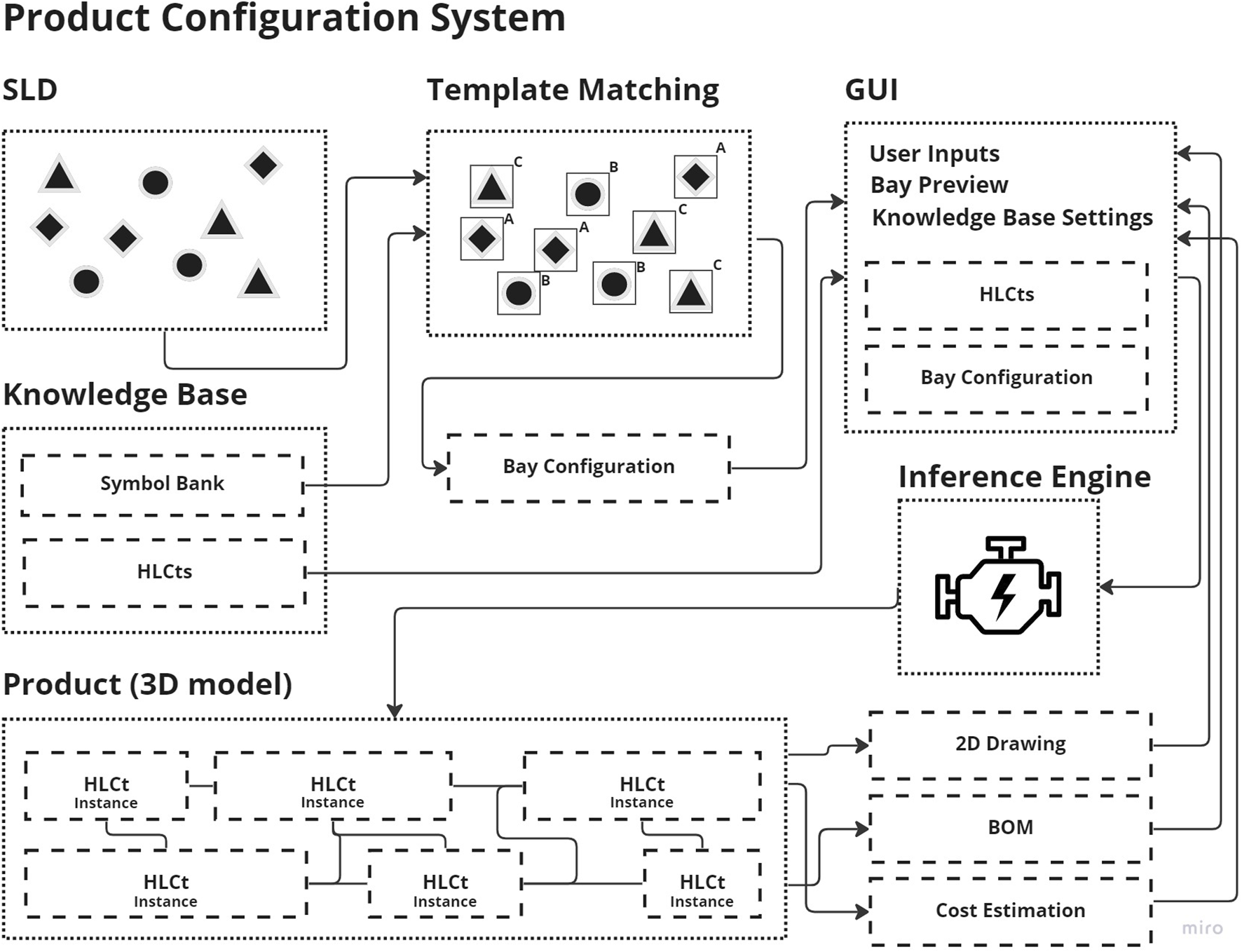
System connectivity and information flowchart in the PCS.
This section explains the in-going parts of the presented framework.
The PCS logic is based on existing substations that were designed using the current design process and are operational today. These substations comply with the laws, regulations, and customer requirements set for each project. In addition, the structure, scope, and application areas of the PCS have been evaluated collaboratively with engineers who work on substation tenders.
3.3.1 Template matching
The SLD is input to the template that matches the symbol bank from the knowledge base. The template matching is completed as described in Subsection 2.3 and shown in Figure 6.
FIGURE 6
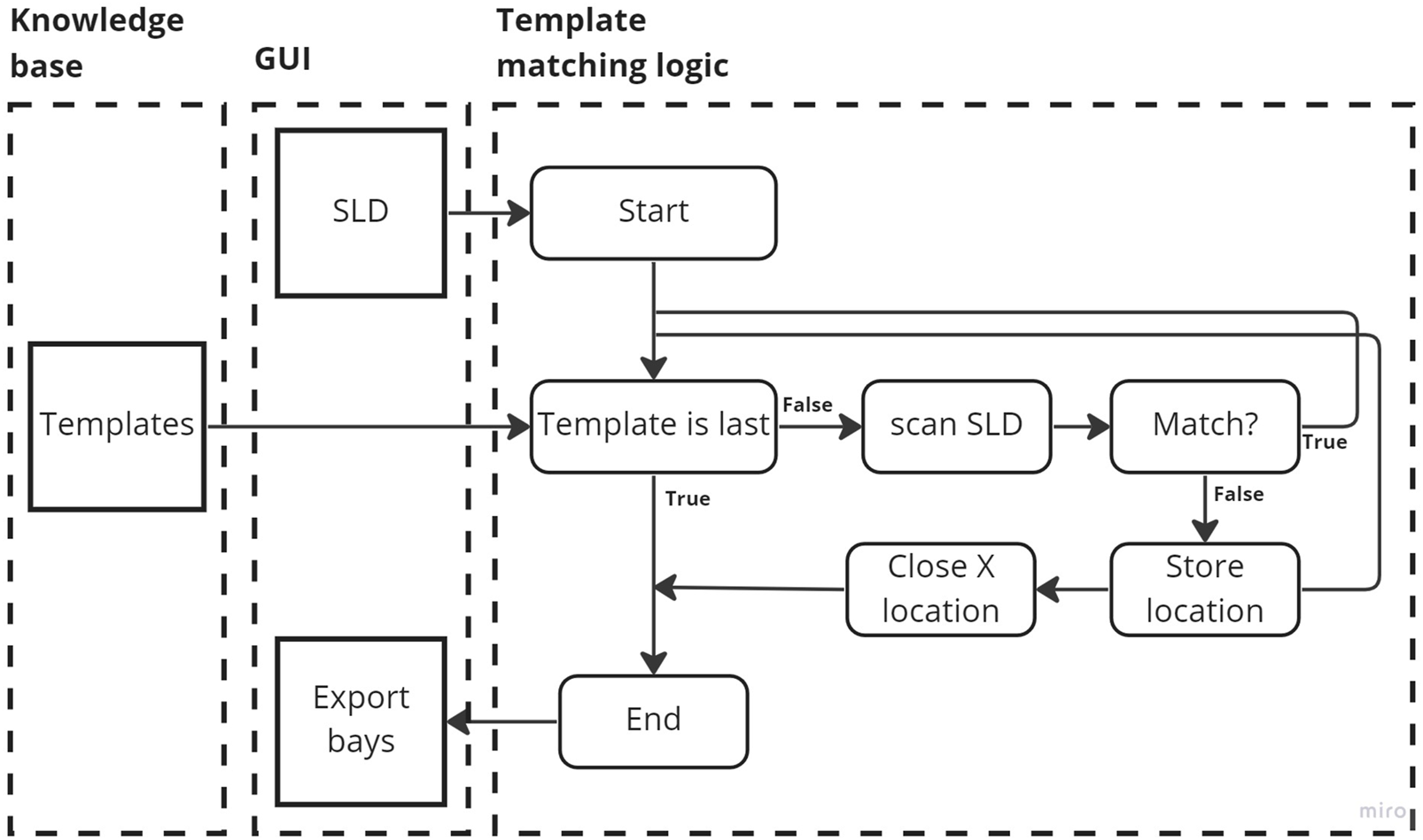
Flowchart outlining the template matching process.
The template matching implementation in the PCS is built using the open-source programming language Python (Python, 2021). In addition, OpenCV, an open-source computer vision and machine learning software library, was used (OpenCV, 2021). The logic of the template matching and configurator integration works can be seen in Figure 6. The script loads a library of images (templates) to search for corresponding matches in the loaded document. These images are stored in a symbol bank organized in a folder system, where one or several similar images represent a specific function in the SLD. During the template matching process, the script searches the SLD bay by bay for matches for each symbol. The algorithm used within OpenCV to find matches is the TM SQDIFF algorithm. Its mathematical formulation is as follows:
where I denotes the image, T denotes the template, and R is the result. The image is where the search is running; it must be in 8-bit or 32-bit floating point format. The template cannot be larger than the image and must have the same data type. The result is a map of the comparison result. It must be a single channel 32-bit floating point format (OpenCV, 2021).
The location of each match is stored and compared to other matches to determine the order of the components. Once all symbols have been scanned, the template matching process is complete, and the loop ends. The script generates an output file that contains the identified types of equipment and their connection order. This file can be imported into a GUI, where the identified equipment is grouped into tabs according to its respective bays.
3.3.2 Knowledge base
As illustrated in Figure 5, the knowledge base consists of two parts of formal reusable knowledge. One part is the symbol bank, which is a database containing SLD symbols. These symbols are grouped in folders, and each folder has multiple instances of the same symbol with distortion, noise, or scale alterations to be used for template matching. The database can easily be extended by adding new image symbols to the folder structure.
The second component of the knowledge base comprises HLCts that hold both CAD data and rules embedded in templates. The rules are influenced by the substation’s configuration and parameters; for instance, the height of a tower’s ground clearance depends on the voltage chosen. The system is structured so that each SLD symbol links to a corresponding HLCt, as depicted in Figure 7.
FIGURE 7
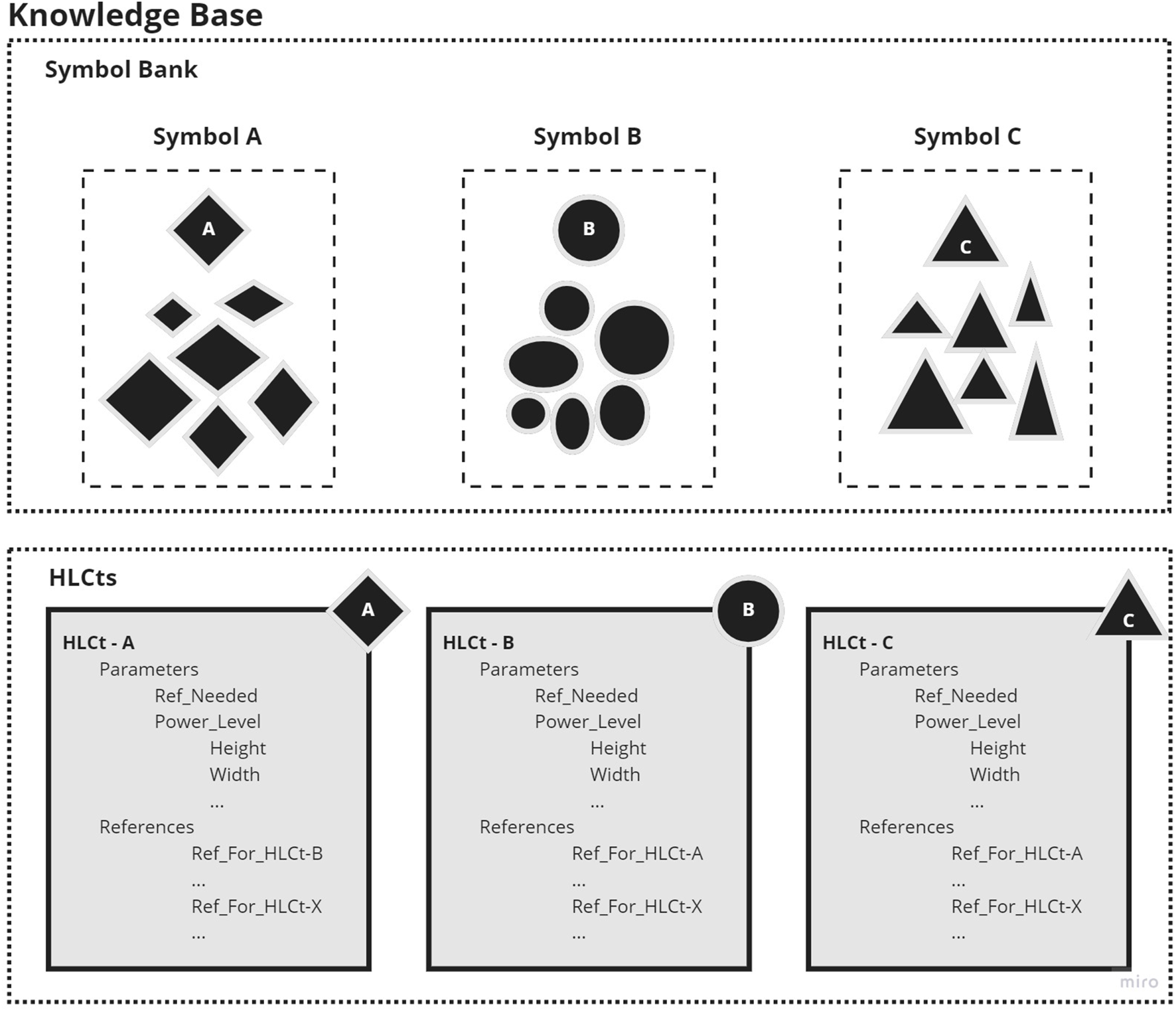
Contents of the knowledge base.
3.3.3 GUI
The developed GUI is an intermediate step between reading from the SLD and writing to the CAD configuration. The GUI can be automatically populated based on content from the scanned SLD. Once the PCS has been populated fully, it can be checked by an engineer, and any modifications can be made, including adding or removing equipment or moving equipment higher or lower in the order within the bay. The user can also change the voltage level of the station and other parameters in the GUI. The selections affect the parameters within the HLCt. The clearances, heights, and sizes of equipment change as the voltage increases or decreases. A GUI populated with information from an SLD is shown in Figure 8.
FIGURE 8

GUI populated with information from an SLD.
3.3.4 Production documentation and preparation
The CAD models are instantiated from a HLCt library containing all equipment necessary. Each HLCt equipment item has its own coordinate system and can be instantiated in relation to a global point of reference or previously instantiated equipment. Settings in the configurator for voltage levels change the clearances between equipment and cables and heights above the ground to ensure the bay is within the specifications and regulations for high-voltage substations.
A BOM can be exported from the fully instantiated CAD model to the GUI. The parts making up the BOM are included in the HLCt and can be used to request quotes from subcontractors or to estimate purchasing orders. Furthermore, complete 2D drawings can be exported for each bay and for the station as a whole. The drawings can be used for production and construction layout.
A cost estimation for the station is compiled from the BOM list and the 3D model. Material weights are exported and can be used to calculate material costs for steel structures.
3.4 Activate
The fourth step is to Activate the solution. For this article, the activation stage is the implementation of the PCS at a substation design company. To evaluate the tool, three cases were processed through the PCS from SLD to CAD, and the time to prepare the CAD, the accuracy of the CAD, and the flexibility to change the design were evaluated in conjunction with employees at the substation design company. SLDs from real projects were used as input to the framework, and the output was compared and discussed with company employees.
4 Result
The developed computer framework fully automates the process of transforming an electrical SLD into a 3D model of a substation. This framework incorporates methods for template matching to identify objects and their connections in the SLD, design rules that govern how electrical equipment can be placed in a substation, CAD models that represent the different types of substation equipment in compliance with the design rules, and document generation for production preparation of the BOM and drawings. The PCS was implemented in several cases by the partner company, which specializes in substation design.
Three cases are presented to showcase the system’s capabilities. Although the cases presented are fictional and somewhat simplified, they were used to test and demonstrate the framework’s potential to handle various scenarios. It is important to note that real stations cannot be presented due to confidentiality reasons. Nonetheless, all three cases are based on real stations, and each was created with an SLD as input to the system. The SLDs for the three cases are shown in
Figure 9, and a brief description of each case is provided as follows:
• Case one is based on a collection station that takes in power from multiple generation sources. The resulting CAD model can be seen in Figure 10.
• Case two is based on a smaller transformer station. The station has one input line, control equipment, and one transformer. The resulting 3D model is shown in Figure 11.
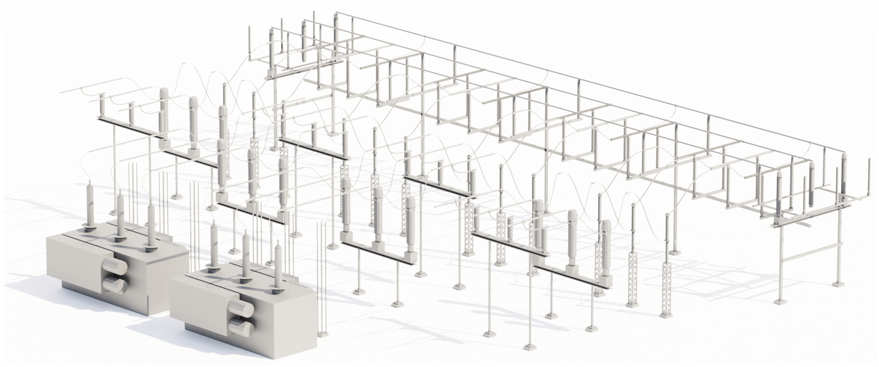
• Case three is based on one of the larger stations constructed in recent years by the company. The resulting station can be seen in Figure 12.
FIGURE 9
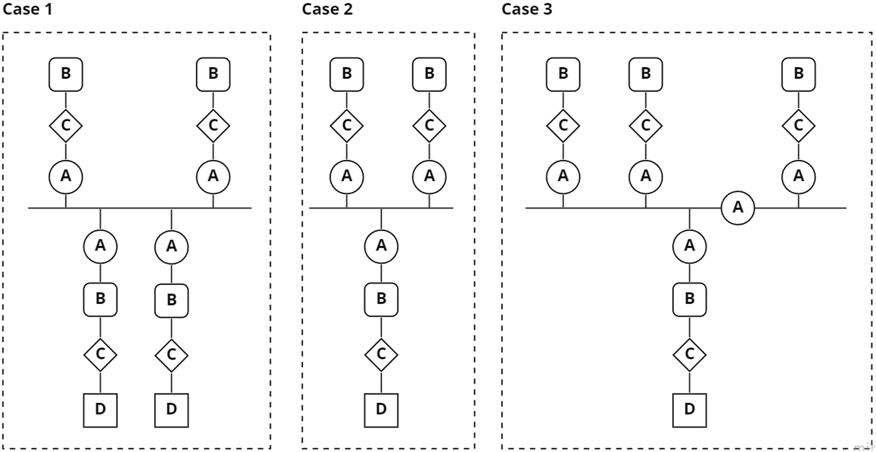
SLD representations of the three cases.
FIGURE 10
3D representation of case 1.
FIGURE 11

3D representation of case 2.
FIGURE 12

3D representation of case 3.
The presented cases show that design concepts that fulfill the quantifiable requirements, CAD models of the concepts, and basic production data can automatically be achieved with the developed PCS. Experts from the partner company included in this study estimate that tender engineering and design activities can be reduced by 40% by adapting the framework presented in this article.
Furthermore, with a more agile way of working, more tenders could be answered as less of the workforce is occupied, which could increase the number of tenders answered, thus increasing the potential of more tenders won.
5 Discussion
Standardized production is crucial in achieving a competitive advantage in the engineering-to-order (ETO) market. To attain standardized production, standardized products, components, and product configurations are essential. To stay competitive in the ETO market, companies must deliver high-quality products at reasonable prices and in a timely manner. This study introduces a framework that integrates KBE and DA methods with a computationally efficient product configurator to enhance competitiveness in complex ETO substation projects. Based on interviews with experts at the collaborating company, it is evident that implementing this framework, which automates many repetitive aspects of the tender process, could potentially reduce the time required for engineering and design activities by up to 50%.
A limitation of the framework is that it is still at a relatively low technical readiness level (TRL). Further work needs to be carried out to increase its TRL, such as adding more high-level components (HLCs) with higher complexity and integrating optimization or other techniques to generate more advanced substation layouts. The integration of cost calculation tools and the inclusion of civil and control building aspects of substation builds could also be considered a limitation.
A universal limitation of KBE frameworks is the continuous updating of the knowledge base and the development of a more refined and integrated user interface. This is crucial for the success of a KBE framework. While this study solely focuses on the design of air-insulated substations (AIS), further studies should also explore other categories of substations, such as indoor AIS and gas-insulated substations (GIS), that serve the same purpose but have different design requirements.
The chosen methods for the development of this framework are motivated by their simplicity. The well-documented and established method of MOKA was a natural method for the development of a KBE method. The selection of template matching, in contrast to, for example, a deep learning approach, is based on the repetitiveness of detected objects. The symbols searched for in an SLD always look the same, and a more elaborate method that would require training would have taken up an inordinate amount of time without adding more value than the selected approach.
A possible future application of the framework is to explore its potential applications in the wider mechanical engineering field. Building the core of the framework with symbol recognition on a 2D product representation and then coupling it to 3D model generation has the potential to be used in many different fields, such as other aspects of DTs. The results of this study contribute to the advancement of knowledge in the field of mechanical engineering and provide valuable insights for professionals and researchers in the industry.
6 Conclusion
A novel automated framework for rationalizing the tendering process for high-voltage substations has been developed and presented in this article. During the knowledge capture process, it was stated that the company could decrease the lead time by 40% by automating various repetitive and manual processes. With the time saved, it is predicted that the companies applying such a process could:
a. Increase the number of tenders participated in,
b. Improve the ratio of successful tenders, and
c. Standardize and improve production efficiency.
The identified process was captured and reused by applying the KBE-based technique of HLCt and the computer vision method of template matching. It is thus possible to automatically read and upload substation configurations from customers’ technical documents in the form of SLDs by applying template matching. The technical document is read, sorted, and translated into configuration formats in the form of HLCts and a knowledge base in the PCS. The engineer can then use the data in the PCS to further test and verify various substation designs that meet the customer’s requirements. The framework lays the foundation for automatically generating DTs with integrated knowledge capture methods. Automatic generation of production drawings can also be further explored and integrated to automatically prepare files for robotics.
Statements
Data availability statement
The raw data supporting the conclusion of this article will be made available by the authors, without undue reservation.
Author contributions
The study conception and design were contributed to by all authors. EN served as the main contributor for material preparation, data collection, and analysis, while AW acted as the project leader. The initial draft of the manuscript was written by EN, with all authors providing feedback on previous versions. The final manuscript was reviewed, read, and approved by all authors.
Funding
This work is part of the AutoKonfig project (2020-02823) and has been financed by PiiA: Digitalization of industrial value chains, Vinnova Sweden.
Acknowledgments
The authors extend their gratitude to PiiA and all partners who participated in the project.
Conflict of interest
The authors declare that the research was conducted in the absence of any commercial or financial relationships that could be construed as a potential conflict of interest.
Publisher’s note
All claims expressed in this article are solely those of the authors and do not necessarily represent those of their affiliated organizations, or those of the publisher, the editors, and the reviewers. Any product that may be evaluated in this article, or claim that may be made by its manufacturer, is not guaranteed or endorsed by the publisher.
References
1
Amaro G. Hendry L. Kingsman B. (1999). Competitive advantage, customisation and a new taxonomy for non make-to-stock companies. Int. J. Operations Prod.19, 349–371. 10.1108/01443579910254213
2
Azevedo M. Tavares S. Soares A. L. (2020). “The digital twin as a knowledge-based engineering enabler for product development,” in Boosting collaborative networks 4.0. PRO-VE 2020. IFIP advances in information and communication technology. Editors Camarinha-MatosL. M.AfsarmaneshH.OrtizA. (Springer, Cham), 598. 10.1007/978-3-030-62412-5_37
3
Bhat N. P. (2022). Engineer to order approaches in sap. Int. J. Comput. Trends Technol.70, 1–6. 10.14445/22312803/IJCTT-V70I5P101
4
Brunelli R. (2009). Template matching techniques in computer vision theory and practice. first edn. Chichester, United Kingdom: John Wiley and Sons Ltd.
5
Carvalho A. Cardoso A. Barreto C. Lamounier E. Lima G. F. M. Mattioli L. R. et al (2016). “A methodology for reducing the time necessary to generate virtual electric substations,” in 2016 IEEE Virtual Reality (VR), Greenville, SC, USA, 19-23 March 2016 (IEEEE). 10.1109/VR.2016.7504704
6
Chapman C. B. Pinfold M. (2001). The application of a knowledge based engineering approach to the rapid design and analysis of an automotive structure. Adv. Eng. Softw.32, 903–912. 10.1016/s0965-9978(01)00041-2
7
Cheng G. Han J. (2016). A survey on object detection in optical remote sensing images. ISPRS J. Photogrammetry Remote Sens.117, 11–28. 10.1016/j.isprsjprs.2016.03.014
8
Cordella L. Vento M. (2000). Symbol recognition in documents: A collection of techniques?IJDAR3, 73–88. 10.1007/s100320000036
9
Curran R. Verhagen W. Van tooren M. Laan T. (2010). A multidisciplinary implementation methodology for knowledge based engineering: Knomad. Expert Syst. Appl.37, 7336–7350. 10.1016/j.eswa.2010.04.027
10
Elgh F. Johansson J. (2020). “Traceability in engineer-to-order businesses,” in Systems engineering in research and industrial practice: Foundations, developments and challenges, 115–145. 10.1007/978-3-030-33312-6_5
11
Gosling J. Naim M. M. (2009). Engineer-to-order supply chain management: A literature review and research agenda. Int. J. Prod. Econ.122, 741–754. 10.1016/j.ijpe.2009.07.002
12
Grabenstetter D. Usher J. (2014). Developing due dates in an engineer-to-order engineering environment. Int. J. Prod. Res.52, 6349–6361. 10.1080/00207543.2014.940072
13
Han Y. (2021). Reliable template matching for image detection in vision sensor systems. Sensors21, 8176. 10.3390/s21248176
14
La Rocca G. Van tooren M. (2007). Enabling distributed multi-disciplinary design of complex products: A knowledge based engineering approach. J. Des. Res.5, 333. 10.1504/jdr.2007.014880
15
Lo C. Chen C. Zhong R. Y. (2021). A review of digital twin in product design and development. Adv. Eng. Inf.48, 101297. 10.1016/j.aei.2021.101297
16
Lovett P. Ingram A. Bancroft C. (2000). Knowledge-based engineering for smes — A methodology. J. Mater. Process. Technol.107, 384–389. 10.1016/S0924-0136(00)00728-7
17
Matsumoto I. Stapleton J. Glass J. Thorpe A. (2005). A knowledge-capture report for multidisciplinary design environments. J. Knowl. Manag.9, 83–92. 10.1108/13673270510602782
18
McDonald J. (2021). Electric power substations engineering. third edn. Boca Raton, FL: Taylor and Francis Group.
19
Nordvall E. Rydebrink K. (2021). Automatic configuration and optimization of photovoltaic parks. MS Thesis. Link¨oping, SWEDEN: Linkoping University.
20
OpenCV (2021). Open source computer vision library. Avaliable at: https://opencv.org/.
21
Paliwal S. Jain A. Sharma M. Vig L. (2021). “Digitize-PID: Automatic digitization of piping and instrumentation diagrams,” in Lecture notes in computer science. Springer International Publishing, 168–180. 10.1007/978-3-030-75015-2_17
22
Python (2021). Python software foundation. Avaliable at: https://www.python.org/.
23
Rahul R. Paliwal S. Sharma M. Vig L. (2019). “Automatic information extraction from piping and instrumentation diagrams,” in International conference on pattern recognition applications and methods, 163–172. 10.5220/0007376401630172
24
Sandberg M. (2015). “Towards a knowledge-based engineering methodology for construction,” in ICCREM 2015, 1–8. 10.1061/9780784479377.001
25
Stark R. Damerau T. (2019). Digital twin. Berlin, Heidelberg: Springer Berlin Heidelberg. 10.1007/978-3-642-35950-716870-1
26
Stephen P. (2022). Effects of knowledge capture and acquisition practices on organizational performance. Eur. J. Inf. Knowl. Manag.1, 43–55. 10.47941/ejikm.854
27
Stjepandic J. Sommer M. Stobrawa S. (2022). Digital twin: A conceptual view. Cham: Springer International Publishing, 31–49. 10.1007/978-3-030-77539-13
28
Stokes M. (2001). Managing engineering knowledge: MOKA: Methodology for knowledge based engineering applications. London: Professional Engineering Publ.
29
Tarkian M. (2012). Design automation for multidisciplinary optimization: A high level CAD template approach. Linköping: Linköping University Electronic Press.
30
Thun O. Bakas S. Storholmen T. C. B. (2022). Development and implementation processes of˚ digitalization in engineer-to-order manufacturing: Enablers and barriers. AI Soc.37, 725–743. 10.1007/s00146-021-01174-4
31
Verhagen W. J. Bermell-Garcia P. van Dijk R. E. Curran R. (2012). A critical review of Knowledge-Based Engineering: An identification of research challenges. Adv. Eng. Inf.26, 5–15. 10.1016/j.aei.2011.06.004
32
Willner O. Gosling J. Schonsleben P. (2016). Establishing a maturity model for design¨ automation in sales-delivery processes of eto products. Comput. Industry82, 57–68. 10.1016/j.compind.2016.05.003
33
Zhang L. (2014). Product configuration: A review of the state-of-the-art and future research. Int. J. Prod. Res.52, 6381–6398. 10.1080/00207543.2014.942012
34
Zhou B. Zhang G. Guo T. Wang J. Niu W. Lv N. et al (2018). “A method of single line diagram 489 layout and optimization for regional distribution system based on ga,” in 2018 Chinese control and decision conference (CCDC) (Spinger), 5303–5307. 10.1109/CCDC.2018.8408053
Summary
Keywords
computer-aided design, knowledge-based engineering, template matching, product configuration system, substation design
Citation
Nordvall E, Wiberg A and Tarkian M (2023) Knowledge-based engineering and computer vision for configuration-based substation design. Front. Mech. Eng 9:1154316. doi: 10.3389/fmech.2023.1154316
Received
30 January 2023
Accepted
23 March 2023
Published
17 April 2023
Volume
9 - 2023
Edited by
Deepak Sharma, University of Kiel, Germany
Reviewed by
Kalyani Kadam, Symbiosis International University, India
Murugesan D., Paavai Engineering College, India
Kosmas Alexopoulos, University of Patras, Greece
Dario Antonelli, Polytechnic University of Turin, Italy
Updates
Copyright
© 2023 Nordvall, Wiberg and Tarkian.
This is an open-access article distributed under the terms of the Creative Commons Attribution License (CC BY). The use, distribution or reproduction in other forums is permitted, provided the original author(s) and the copyright owner(s) are credited and that the original publication in this journal is cited, in accordance with accepted academic practice. No use, distribution or reproduction is permitted which does not comply with these terms.
*Correspondence: Anton Wiberg, anton.wiberg@liu.se
This article was submitted to Digital Manufacturing, a section of the journal Frontiers in Mechanical Engineering
Disclaimer
All claims expressed in this article are solely those of the authors and do not necessarily represent those of their affiliated organizations, or those of the publisher, the editors and the reviewers. Any product that may be evaluated in this article or claim that may be made by its manufacturer is not guaranteed or endorsed by the publisher.