 B. Jalili
 P. Jalili1
 D. D. Ganji
- 1Department of Mechanical Engineering, North Tehran Branch, Islamic Azad University, Tehran, Iran
- 2Department of Mechanical Engineering, Tarbiat Modares University, Tehran, Iran
- 3Department of Mechanical Engineering, Babol Noshirvani University of Technology, Babol, Iran
This study presents experimental findings on the crossflow injection of a liquid jet into a gaseous flow. Crossflow injection is favored over co-axial trajectory injection because of its potential to enhance atomization, promote the formation of smaller droplets, and improve injection parameters, mainly due to the differing trajectory of fuel injection within the transverse airflow. The study’s experiments use two circular and four elliptical nozzles with varying aspect ratios. The research investigates the influential factors that affect the trajectory and breakup of the liquid jet, specifically analyzing the impact of the nozzle geometry, Weber number, and momentum ratio of the liquid jet to the air crossflow. Additionally, equations are derived to describe the trajectory for both elliptical and circular nozzles. The relationship between breakup height and length is explored, with the observation that breakup length remains constant for both nozzle shapes. Furthermore, the study investigates the analysis of breakup regimes and establishes a direct correlation between the Weber number and the breakup regime. Column, bag, and multimode breakup are observed at Weber numbers 4, 38, and 82, respectively. The experimental error for the liquid jet trajectory obtained is approximately 2%. Importantly, the experimental results align with previously published experimental and numerical data, confirming the validity and reliability of the findings.
1 Introduction
The flow field associated with injecting a transverse fluid jet into a crossflow can be divided into two main categories. The first type of gas jet (or liquid) within the transverse gas flow (or liquid) is called a “single-phase flow”. The second type of gas jet (or liquid) within the transverse flow of liquid (or gas) is known as a “two-phase flow.” Crossflow jet applications have various uses in industry, environmental systems, and nature. Examples of these applications include airborne engines (such as diluted air jets, turbine blast cooling, and fuel injection in jet and scramjet systems), rocket motors (for thrust vector control), environmental control systems (including smoke from chimneys and from ship or train funnels), and natural phenomena (like volcanic lava in crosswinds). There has been initial research on the environmental applications of transverse flow, such as the dispersion of exhaust or chimney outlet smoke or liquid wastewater in the airflow (Gurevich et al., 2018; Wen et al., 2020; Niu et al., 2022; Jalili and Jalili, 2023).
The thrust vector control of rocket motors using a row of crossflow jets is used to disperse the nozzle fluid for gas and liquid jets. This jet structure is also used to control lift and thrust vectors during lifting, stationary, and wing-borne flight (Li et al., 2022). Better jet mixing properties are more attractive for engineering applications than jets in stationary air, especially where fast mixing is essential. Additionally, the dilution of gas jets in the primary or secondary combustion chamber is used to reduce the temperature of combustion products before entering the turbine area, making it an application of crossflow jets (Ukamanal et al., 2020). Transversely injecting liquid fuel into a crossflow is commonly used in ground and air power generation systems, where rapid fuel penetration, evaporation, combustion, and, ultimately, stable combustion processes are considered (Keramaris and Pechlivanidis, 2020). Cross-injection of the jet is one of the most advanced methods for fuel injection systems, thanks to proper atomization and a high evaporation rate. Moreover, the momentum ratio and adjustable injection angles, or even a swirl injector, can be used to achieve the desired fuel-to-air ratio. These elements are crucial in achieving the desired air and fuel mixture quality. Ultimately, all of those mentioned previously contribute to reducing the production of environmental pollutants, increasing combustion efficiency, and decreasing fuel consumption (Cerri et al., 2007).
The nature of crossflow is volatile. These instabilities are due to the boundary layer near the walls and turbulence in the flow. Physical complexities arise from the strong vortex structure, small-scale waveforms, the separation of tiny droplets from the jet surface, and the formation of ligaments and droplets of different sizes. Theoretical studies have generally been used to obtain initial information on the formation of a jet and its trajectory. Empirical studies have also obtained information about changes in jet trajectory and jet breakup mechanisms. Iyogun et al. (2006) showed that a larger injector diameter would increase penetration depth at the same momentum ratio. They also showed that an increase in the momentum ratio results in deeper penetration for a constant injector diameter. Lakhamraju (2003) studied the effect of ambient temperature on the jet trajectory and penetration depth and found that the latter decreases with increasing ambient temperature. They also observed that, with an increasing momentum ratio, the breakup length does not change and remains constant. Bellofiore et al. (2007) experimentally studied transverse airflow with high temperature and pressure. They showed that the liquid-to-gas momentum ratio, Reynolds gas number, and aerodynamic Weber number are essential for determining the breakup point. Wang et al. (2011) studied the injection of plate jets in a gas crossflow. They experimentally examined the penetration and diffusion of the liquid jet and obtained relationships for the liquid column’s penetration, breakup time, and instability frequency. Bai et al. (2009) investigated the effects of different angles of swirl jets on the mixing ratio of gas and liquid phases. They discovered that increased gas turbulence increases the mixing rate. Birouk et al. (2007) studied the effect of liquid viscosity on jet penetration and trajectory in a low-speed gas crossflow.
This paper is an experimental and comprehensive study of effective parameters on the trajectory and penetration of a liquid jet in the gaseous crossflow. It investigates the effect of nozzle output geometry, momentum ratio, and Weber number. The main focus of this study is nozzle geometry, which considers elliptic and circular nozzles of different diameters. It also investigates its effect on the liquid jet’s trajectory, penetration, and initial rupture length. Most previous studies have used a limited range of Weber numbers and momentum ratios (essentially representing the liquid jet velocity and transverse air velocity). However, this paper employs a more extensive range for examination.
1.1 Experiment apparatus
Equipment used in the laboratory test, as shown in Figure 1, could be classified into three main categories: the air supply system, fuel system, and imaging and detection system.

FIGURE 1. (A) Experimental setup. (B) Schematic diagram.
1.2 Air supply system
The airflow generation in this setup involved using a Gebhardt company centrifugal blower, operating at a speed of 2,750 rpm, with the capacity to generate up to 35% of a cubic meter per second (Figure 2A). The LS company employs a converter (Figure 2B) capable of modulating the blower’s speed to control and adjust flow rates within the channel. This converter achieves different channel velocities by altering the motor’s input frequency, ranging from 0 to 60 Hz, changing the engine’s speed from 0 to 2,750 rpm, and the flow speed from 0 to approximately 53 m/s.
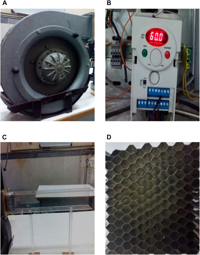
FIGURE 2. (A) Blower, (B) converter, (C) duct, and (D) honeycomb.
The primary structure of the wind tunnel was crafted from Plexiglas. It possessed a cross-section measuring 50 × 80 mm and extended over a length of 60 cm. The transparent nature of Plexiglas enables optical measurements during testing. The Plexiglas sheet was 2-mm-thick, and the nozzle was positioned 30 cm into the channel. The initial 30 cm of the channel streamlined and smoothed the flow (Figure 2C).
A honeycomb composed of hexagonal aluminum cells (Figure 2D) was employed to enhance flow stability and minimize vertical velocity components. These hexagonal cells comprised multiple tubes that effectively reduced the intrusion of large-scale eddies into the airflow. The honeycomb structure utilized in this study was 35-mm-long and was characterized by 6-mm regular hexagons.
To ensure the stability of the channel and prevent unwanted vibrations, two solid Plexiglass base holders with a cross-section of 20 × 20 mm were employed. Additionally, 100 × 100 mm Plexiglass sheets were used to maintain balance on the base and table. Furthermore, a support holder was covered with fiber and polystyrene to prevent vibrations in the blower.
1.3 Fuel supply system
Injecting a liquid jet vertically into the air stream requires a specific route for fuel injection at the desired speed by the jet supply system. Due to natural fuel limitations, water was used as a fluid injected into the stream. Injections of fluid into the transverse airflow at the desired speed required increased pressure behind the fluid using a pressurized tank (Figure 3A). The tanker was partially filled with liquid and pressurized by a gas. We could then adjust the flow rate in the nozzle outlet using a regulator valve. A flow meter was used to obtain the rate of the fluid jet in the nozzle outlet. The outlet speed of the nozzle was easily calculated by measuring the inlet flow and the nozzle area. The Besta Company made the flowmeter used, in the range of 0.16–1.6 L per minute (Figure 3B). The nozzle used here was a simple orifice, and was circular and elliptical in different dimensions (Figure 3C). Four configurations for the nozzle outlet were considered. In two cases, the nozzle outlet was circular with diameters of 1 and 2 mm, and in the other two cases, elliptical nozzles with major and minor radii of 1 and 2, and 1 and 4 mm, respectively, were constructed. These nozzles were fabricated using a super drill and wire cutter and were specifically designed for this paper. When the smaller diameter faced the wind direction, the aspect ratio was less than 1, and when the same nozzle had its larger diameter facing the wind, the aspect ratio became greater than 1. Thus, depending on its orientation relative to the wind, two aspect ratios smaller and greater than 1 could be achieved with a single nozzle.
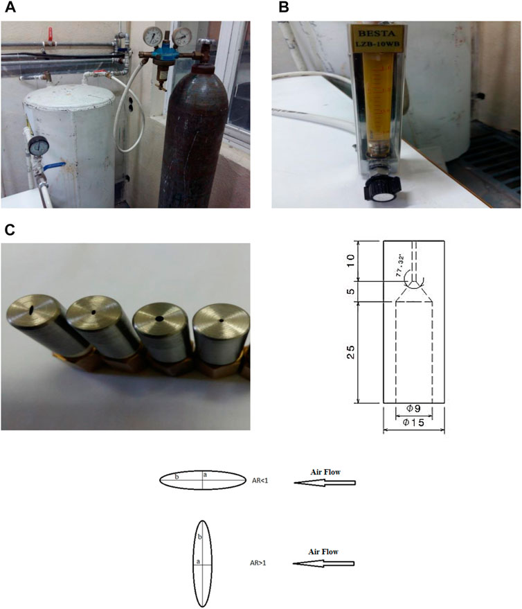
FIGURE 3. (A) Pressurized tank, (B) flowmeter, and (C) view of the nozzles used and nozzle structure.
1.4 Image processing and detection system
In this study, shadowgraphy was used to detect crossflow. We required detection and imaging systems to capture relatively good-quality images for crossflow analysis. The camera used in this test was a Casio EX-F1 camera that can take pictures at 1,200 frames per second.
This study used 25-micron-long time exposure photography, which is the maximum time that could be achieved with the present camera. Due to the low time exposure, it needed a vital light source, as explained in the following paragraphs. The most important effect of the time exposure on the photographs was that the lower the number, the less light the camera sensor needed. For example, if the droplets were flowing, they could be depicted with a relatively low resolution with low lightning time.
For a light source, a projector with an Onomat 1000-W bulb was used due to the type of lens mounted on it and the surrounding protections; its light output was relatively uniform (Figure 4A). To measure the speed of the incoming air, a hot wire anemometer model 1,340, manufactured by Tess Corporation with an error of less than 3% was used. (Figure 4B).
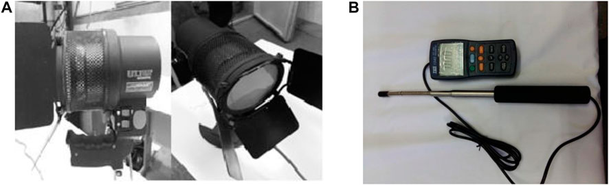
FIGURE 4. (A) View of the projector. (B) Hot wire.
Measurement of the velocity profile in the test’s transverse section showed that this section’s velocity profile was uniform. The speed of blown air varied from 7.6 to 51.8 (ms−1). The fluid tested was water; the use of water instead of fuel is routine and was used as the scavenged fluid. Since nozzles with different openings were used in this experiment, the speed of the outlet water of the nozzle was different. However, water velocity generally varied from 1.06 to 33.95. The test temperature was an ambient 25 °C (Table 1).
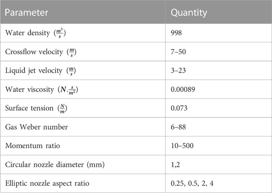
TABLE 1. Experimental conditions.
Because this is a study on crossflow, there are many non-dimensional numbers in the problem. The following are the dimensionless numbers used in this experiment (Ashgriz, 2011). The momentum ratio number is defined as the ratio of the liquid jet momentum to the gas momentum (liquid jet dynamic pressure to the dynamic gas pressure):
In relation (1),
In relation (2), d is the diameter of the nozzle and
The liquid Weber number is defined as the gas Weber number:
The gas Reynolds number is defined as the ratio of inertia to the viscous force:
where
The liquid Reynolds number is also defined as follows:
Eqs 1–5 were used to obtain the Mach number for gas and liquid, as well as the Reynolds number for gas and liquid and the momentum ratio. As can be seen, the dimensionless numbers are determined after plugging the values obtained from Table 1 into these equations.
2 Results and discussion
2.1 Penetration and trajectory of liquid jet
The trajectory and penetration of a liquid jet into a transverse gas flow are critical parameters for a fluid jet. They directly influence the distribution of fuel injection within the combustion chamber, the process of evaporation, and the rate of mixing with the oxidizing agent. It is also essential to design the combustion chamber to prevent the liquid jet from impacting the chamber walls. The observations from this study reveal that, when a liquid jet is injected into calm air, it maintains a straight trajectory and does not collide with the upper wall of the test section. It is important to note that these observations are based on small-scale dimensions. In larger-scale scenarios, the fluid jet may indeed deflect and not reach the upper surface of the channel.
A schematic representation of the fluid jet being sprayed into the transverse air is shown in Figure 5. The liquid separates from the surface of the jet column in the form of a liquid strip. Due to hydrodynamic instability, the liquid jet, which initially leaves the nozzle as a continuous column, becomes unstable along its length, leading to its eventual breakup into ligaments—a “column breakup.” Subsequently, the separated liquid pieces along this trajectory transform into smaller droplets that enter the combustion chamber.
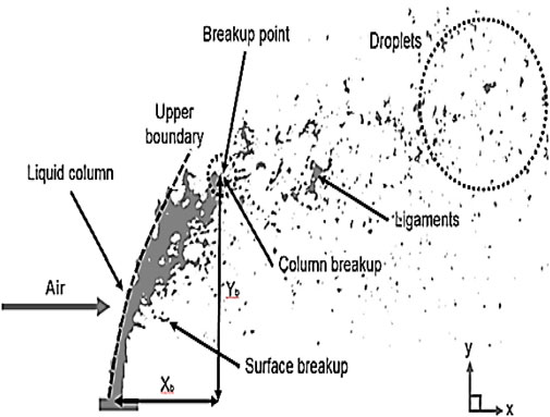
FIGURE 5. View of injection of the liquid jet structure (Stenzler et al., 2006).
Figure 6 shows the injected fluid jet in the transverse airflow for circular nozzles. The overall process of the liquid jet breaking into the airflow and forming the spray in different nozzles is the same, and, depending on the geometry used, the length of penetration and breakup will be different.
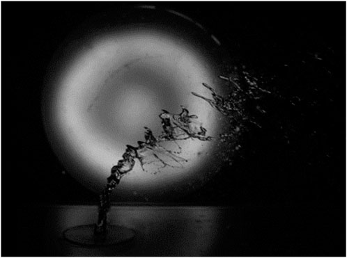
FIGURE 6. View of a liquid jet in crossflow.
Figure 7 shows the liquid jet trajectory for the geometry of different nozzles. In each geometry, liquid velocity, and the different air velocities, several photographs were taken at the time, with a total of 2,100 photographs. To better detect the boundaries of the liquid jet column and detect the breakup point, we took the average of photographs at the same conditions using MATLAB software (Supplementary Appendix SA).
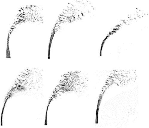
FIGURE 7. View of a liquid jet in crossflow with a different nozzle geometry.
Figure 8 illustrates the impact of transverse air velocity on the penetration depth of the liquid jet. It is evident from the figure that, as the air velocity quantified by the Weber number increases, the penetration depth of the liquid jet decreases. This is due to the increased drag force caused by the higher velocity, which prompts the liquid jet to deviate from its earlier path, resulting in a reduced penetration depth.
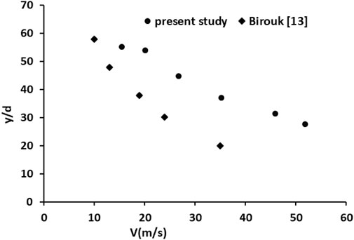
FIGURE 8. Effect of air velocity on liquid jet penetration.
The observed change in penetration depth aligns with findings from other studies. However, it is important to note that this study differs from previous research regarding the fluid used, which is not oil. Additionally, the velocities employed in this study are distinct. The primary objective of this research is to examine how variations in transverse air velocity affect the penetration depth of liquid jets, particularly when dealing with nozzles of different geometries.
In this research, two circular nozzles with diameters of 1 and 2 mm, two elliptical horizontal nozzles with a small diameter of 1 mm and large diameters of 2 and 4 mm, and two elliptical vertical nozzles with a small diameter of 1 mm and large diameters of 2 and 4 mm were used. Laboratory tests were first performed with a circular nozzle with a diameter of 1 mm, and then, a circular nozzle with a diameter of 2 mm was used. Oval nozzles performed another part of the laboratory tests. The results are shown in the following diagrams. As shown in Figure 9, the behavior of the liquid jet is the same for all nozzles, so the liquid jet penetration decreases with the increasing amount of transverse air velocity, assuming that other parameters are constant.
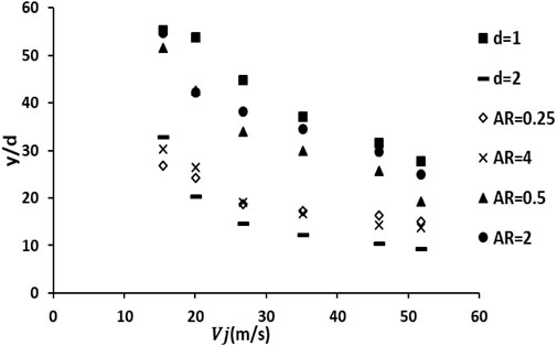
FIGURE 9. Effect of air velocity on liquid jet penetration for different nozzle geometry.
The impact of nozzle geometry on the penetration of the liquid jet can be studied while maintaining a constant Weber number and momentum ratio. Figure 10 demonstrates that the velocity of incoming air decreases for circular geometries with increasing diameter while holding the Weber number constant. Conversely, at a constant momentum ratio, the velocity of the inlet liquid increases due to the momentum ratio formula (q). With lower air velocity at a larger diameter, a reduced drag force is exerted on the liquid. The increased fluid velocity also results in higher momentum, leading to a greater penetration depth. Similar principles apply to elliptic nozzles, meaning that the penetration depth increases as the ratio of the larger to smaller diameters increases while keeping Weber’s number and momentum ratio constant. When there are the same areas but with opposite dimensions, where the smaller diameter is aligned with the flow direction and the larger diameter is oriented perpendicularly to the transverse flow, it is evident that the penetration depth is greater. In cases where the minor diameter is aligned perpendicular to the transverse flow, the airflow encounters less surface area, resulting in reduced drag force on the liquid jet and, consequently, deeper penetration of the liquid jet.
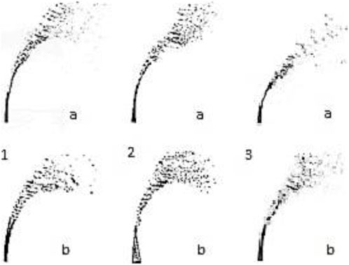
FIGURE 10. Effect of nozzle geometry on liquid jet penetration, 1. (a) AR= 4, (b) AR = 0.25; 2. (a) AR = 2, (b) AR = 0.5; 3. (a) d = 2 mm, (b) d = 1 mm.
Considering the upper boundary of the liquid jet trajectory for the circular nozzle, we can determine the equation of the liquid injection trajectory using linear regression. Considering the circular nozzle with a diameter of 1 mm, the equation of the liquid jet trajectory was obtained as follows:
As shown in Figure 11, the liquid-jet injection trajectory agrees very well with previous research, and the difference may be due to factors such as the experimental equipment, the difference between the momentum ratio, and Weber numbers.
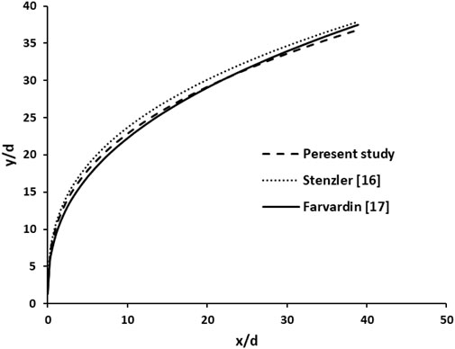
FIGURE 11. Liquid jet trajectory for a circular nozzle.
Linear regression can also be used to obtain the elliptical nozzle injection trajectory. The direction equation for the elliptical nozzle is obtained as follows:
A specific diameter should be used to make the jet spray trajectory dimensionless and the diameter used in the Weber number into an elliptical nozzle. For this purpose, it should be considered equivalent to the following diameter:
where a is a large diameter, b is a small diameter oval, and
2.2 Length and height of breakup
As mentioned, two distinct breakup processes exist for liquid jets in transverse flow: surface and column breakup. The liquid forms a continuous column between the nozzle outlet and the breakup point. Determining the exact location of this breakup is crucial for modeling fluid jets in transverse airflow. However, obtaining a precise location can be challenging, primarily due to the presence of high-density droplets. As shown in Figure 12, the length of the breakup
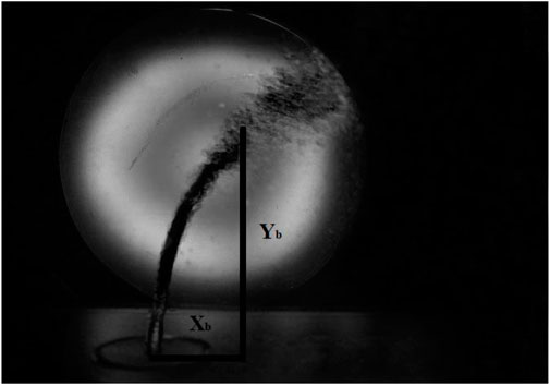
FIGURE 12. Length and height of breakup.
To determine the breakup length, it is necessary to identify the coordinates of the breakup point by examining various combinations of momentum ratios and Weber numbers for a given nozzle. This process allows for the derivation of relevant relationships. Interestingly, the difference in breakup length is minimal when considering various values of q and Weber numbers less than 10, essentially making it a constant value for these scenarios. Similarly, another constant value can be established for different q values and Weber numbers exceeding 10. As a result, we can derive the following fixed values for the breakup length:
To obtain the height of the breakup, the height should be calculated by considering the momentum ratio and different Weber numbers. Then, the height of the breakup equation is obtained, which is as follows for the Weber number greater and smaller than 10:
2.3 Breakup regimes
Much research (Mazallon et al., 1999; Sallam et al., 2004; Zhang et al., 2013; Song et al., 2017) has demonstrated that the Weber number influences the breakup pattern of a liquid jet. The initial phase in a liquid jet’s breakup involves the formation of a strip-like ligament. The presence of vortices in the crossflow induces waves on the surface of the liquid column jet. These waves gradually grow, ultimately leading to the fragmentation of the liquid jet into ligaments. These separated segments are exposed to the dynamic air pressure, causing them to break into smaller droplets. This force leads to the dispersion of the liquid jet column, transforming it into a bean-like shape. The phenomenon where a liquid jet breaks into ligaments is commonly referred to as “column breakup” (Figure 13).
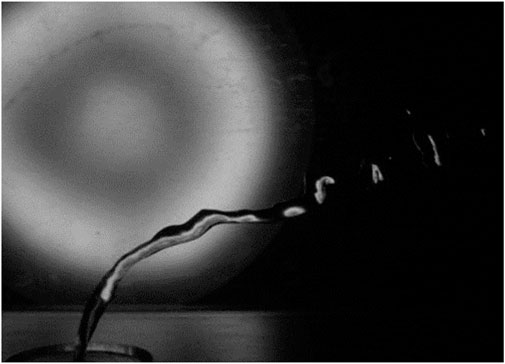
FIGURE 13. Column breakup.
Another kind of breakup appears with the increase in the Weber number. In this kind of breakup, a hollow layer of liquid is formed as a bag shape. The time of its formation is brief because aerodynamic force overcomes surface tension, and bags change to small particles. The bag breakup is shown in Figure 14. In Part 1, bag breakup is produced and, in Part 2, changes to small particles.
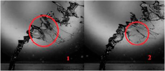
FIGURE 14. Bag breakup.
The bag breakup has vanished to increase the Weber number, and small particles (much smaller than the nozzle diameter) are separated from the liquid column. This step combines a different kind of breakup called multimode breakup. In this regime, particles separate from the bottom part before the breakup because of increasing aerodynamic force (Figure 15).
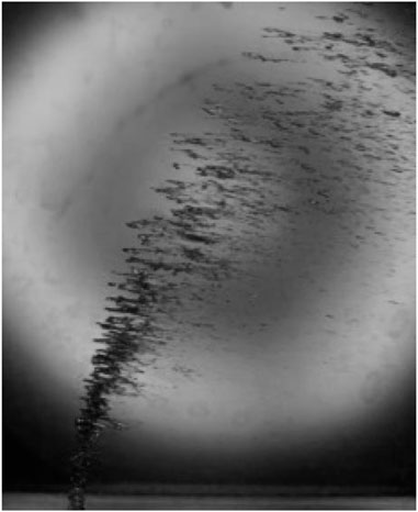
FIGURE 15. Multimode breakup.
As shown in Figure 16, the breakup pattern changes when increasing the Weber number while maintaining an equal momentum ratio and nozzle diameter. Specifically, Weber numbers 2, 16.6, and 62 are considered for different sections. At Weber number 2, the growth of surface instability is prolonged, allowing sufficient time for forming ligaments. In the case of Weber number 16.6, dynamic pressure increases, leading to the growth of waves on the liquid jet’s surface and resulting in a “bag breakup”. After a period, aerodynamic forces overcome surface tension, causing the bags to break and form small particles. These bags represent only a portion of the liquid jet, with the remainder transforming into ligaments or larger particles. With the Weber number increasing to 62, the aerodynamic forces applied to the column jet intensify. These forces surpass the surface tension in each segment, and particles separate from the jet’s surface. In this scenario, bag breakup is minimal and quickly transitions into small particles. A comparison of these results with previous studies is presented in Table 2.
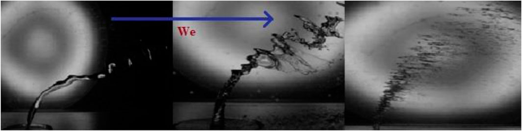
FIGURE 16. Breakup regimes based on the Weber number increase.
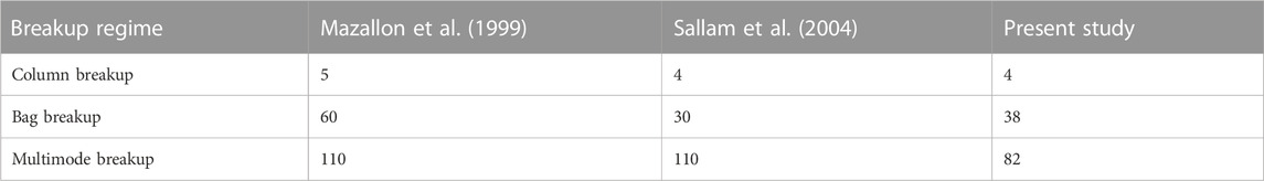
TABLE 2. Breakup regimes based on Weber’s number.
2.4 Error analysis
In this article, the variance method is used to obtain the uncertainty of the test results. Considering the w function as follows,
The error propagation for the function given in relation 11 is calculated using the variance method thus:
In relation 11, all parameters from
Now the error is obtained for each of the aforementioned sentences separately.
The momentum ratio error (Eq. 1) can be obtained from the following equation.
After derivation from relationship q and placing it in the aforementioned equation, we derive a relation as follows.
In the aforementioned relationship,
The liquid velocity error can be obtained thus:
To obtain the approximate error for Eq. 11, it is necessary to know the error of each of the primary quantities. All errors are shown in Table 3.
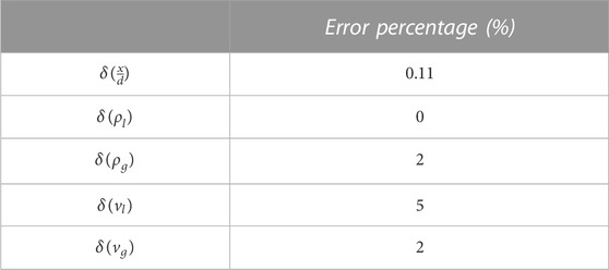
TABLE 3. Error percentage.
Considering the aforementioned error values, the error value
3 Conclusion
Jet cross-injection, due to proper atomization and high evaporation rate, is one of the most advanced methods for a fuel injection system, and its study is of great importance due to its extensive application in various industries. This paper investigated the effect of nozzle geometry on a liquid jet trajectory, and the trajectory equation was obtained for circular and elliptic jets. The following summary results were obtained.
• By increasing the circular nozzle diameter, the penetration depth increases. For example, we take into account the drag force for a 2-mm and a 1-mm-diameter nozzle, considering that the wetted cross-sectional area for calculating the drag force is proportional to the nozzle diameter and that the gas velocity squared power for the 2 mm nozzle is twice that of the 1 mm nozzle. Consequently, the drag force remains unchanged when the nozzle cross-sectional area increases. On the other hand, for the momentum produced by the liquid jet, since momentum is related to the cross-sectional area and the inlet velocity of the nozzle, the inlet velocity becomes
• The penetration depth in the elliptic nozzle increases as the aspect ratio increases. Increasing the ratio of the larger to smaller diameters in a given Weber number and a specified momentum ratio results in greater liquid jet penetration; this applies similarly to a circular nozzle. As the area ratio increases while keeping the Weber number constant, the drag force for an area ratio of 2 is equal to the drag force for an area ratio of 4. On the other hand, the momentum force increases because the area doubles and the velocity doubles. As a result, with the increased momentum force and decreased back pressure, the penetration depth also increases.
• The penetration depth decreases with increasing transverse air velocity for both circular and elliptical nozzles.
• For different momentum ratios and Weber numbers, the breakup length is almost constant, and the breakup height is related to the momentum ratio, which is different for Weber numbers less than and more than 10.
Data availability statement
The raw data supporting the conclusion of this article will be made available by the authors, without undue reservation.
Author contributions
All authors listed have made a substantial, direct, and intellectual contribution to the work and approved it for publication.
Conflict of interest
The authors declare that the research was conducted in the absence of any commercial or financial relationships that could be construed as a potential conflict of interest.
Publisher’s note
All claims expressed in this article are solely those of the authors and do not necessarily represent those of their affiliated organizations, or those of the publisher, the editors, and the reviewers. Any product that may be evaluated in this article, or claim that may be made by its manufacturer, is not guaranteed or endorsed by the publisher.
Supplementary material
The Supplementary Material for this article can be found online at: https://www.frontiersin.org/articles/10.3389/fmech.2023.1207894/full#supplementary-material
References
Bai, B., Zhang, H., Liu, L., and Sun, H. J. (2009). Experimental study on turbulent mixing of spray droplets in crossflow. Exp. Therm. Fluid Sci. 33, 1012–1020. doi:10.1016/j.expthermflusci.2009.05.002
Bellofiore, A., Cavaliere, A., and Ragucci, R. (2007). Air density effect on the atomization of liquid jets in crossflow. Combust. Sci. Technol. 179, 319–342. doi:10.1080/00102200600809563
Birouk, M., Iyogun, C. O., and Popplewell, N. (2007). Role of viscosity on trajectory of liquid jets in a cross-airflow. Atomization Sprays 17 (3), 267–287. doi:10.1615/atomizspr.v17.i3.30
Cerri, G., Giovannelli, A., Battisti, L., and Fedrizzi, R. (2007). Advances in effusive cooling techniques of gas turbines. Appl. Therm. Energy 27, 692–698. doi:10.1016/j.applthermaleng.2006.10.012
Farvardin, E., Johnson, M., Alaee, H., Martinez, A., and Dolatabadi, A. (2013). Comparative study of biodiesel and diesel jets in gaseous crossflow. J. Propuls. Power 29 (6), 1292–1302. doi:10.2514/1.b34743
Gurevich, A. Y., Goman, M. G., Gurevich, Y. G., and Lopez, A. M. (2018). Synthetic turbulence modeling for evaluation of ultrasonic cross-correlation flow measurement. Flow Meas. Instrum. 60, 134–143. doi:10.1016/j.flowmeasinst.2017.12.013
Iyogun, C. O., Birouk, M., and Popplewell, N. (2006). Trajectory of water jet exposed to low subsonic crossflow. Atomization Sprays 16 (8), 963–980. doi:10.1615/atomizspr.v16.i8.70
Jalili, B., and Jalili, P. (2023). Numerical analysis of airflow turbulence intensity effect on liquid jet trajectory and breakup in two-phase cross flow. Alexandria Eng. J. 68 (2023), 577–585. doi:10.1016/j.aej.2023.01.059
Keramaris, E., and Pechlivanidis, G. (2020). Boundary effects of vertical buoyant jets in a stagnant fluid in a crossflow. Exp. Tech. 44 (2), 149–158. doi:10.1007/s40799-019-00320-4
Lakhamraju, R. R. (2003). Liquid jets in subsonic airstream at elevated temperatures. PhD Thesis. Ohio, OH, USA: University of Cincinnati.
Li, S., Wu, J., and Ma, F. (2022). Choking flow characteristics of the rectangular slot-type flip bucket. Exp. Tech. 47, 211–222. doi:10.1007/s40799-021-00532-7
Mazallon, J., Dai, Z., and Faeth, G. M. (1999). Primary breakup of nonturbulent round liquid jets in gas crossflows. At. Sprays 9, 291–312. doi:10.1615/atomizspr.v9.i3.40
Niu, H., Yi, S., Liu, X., Huo, J., and Zheng, W. (2022). Experimental study of hypersonic traveling crossflow instability over a yawed cone. Acta Astronaut. 193, 173–181. doi:10.1016/j.actaastro.2021.12.016
Sallam, K. A., Aalburg, C., and Faeth, G. M. (2004). Breakup of round nonturbulent liquid jets in gaseous crossflow. AIAA J. 42, 2529–2540. doi:10.2514/1.3749
Song, Y., Hwang, D., and Ahn, K. (2017). “Effect of orifice geometry on spray characteristics of liquid jet in crossflow,” in Proceedings of the 55th AIAA Aerospace Sciences Meeting, Grapevine, Texas, USA, January, 2017.
Stenzler, J., Lee, J., Santavica, D., and Lee, W. (2006). Penetration of liquid jets in a crossflow. Atomization Sprays 16 (8), 887–906. doi:10.1615/atomizspr.v16.i8.30
Ukamanal, M., Mishra, P. C., and Sahoo, A. K. (2020). Effects of spray cooling process parameters on machining performance AISI 316 steel: a novel experimental technique. Exp. Tech. 44 (1), 19–36. doi:10.1007/s40799-019-00334-y
Wang, Q., Mondragon, U. M., Brown, C. T., and McDonell, V. G. (2011). Characterization of trajectory, break point, and break point dynamics of a plain liquid jet in a crossflow. Atomization Sprays 21 (3), 203–219. doi:10.1615/atomizspr.2011002848
Wen, J., Hu, Y., Nakanishi, A., and Kurose, R. (2020). Atomization and evaporation process of liquid fuel jets in crossflows: a numerical study using Eulerian/Lagrangian method. Int. J. Multiph. Flow 129, 103331. doi:10.1016/j.ijmultiphaseflow.2020.103331
Keywords: experimental study, crossflow, liquid jet, elliptical nozzle, breakup regime
Citation: Jalili B, Jalili P, Ommi F and Ganji DD (2023) Experimental study on the nozzle-shape effect on liquid jet characteristics in gaseous crossflow. Front. Mech. Eng 9:1207894. doi: 10.3389/fmech.2023.1207894
Received: 18 April 2023; Accepted: 24 October 2023;
Published: 15 November 2023.
Edited by:
Farschad Torabi, K. N. Toosi University of Technology, IranReviewed by:
Ebrahim Afshari, University of Isfahan, IranAzadeh Shahidian, K. N. Toosi University of Technology, Iran
Copyright © 2023 Jalili, Jalili, Ommi and Ganji. This is an open-access article distributed under the terms of the Creative Commons Attribution License (CC BY). The use, distribution or reproduction in other forums is permitted, provided the original author(s) and the copyright owner(s) are credited and that the original publication in this journal is cited, in accordance with accepted academic practice. No use, distribution or reproduction is permitted which does not comply with these terms.
*Correspondence: D. D. Ganji, ZGRnX2Rhdm9vZEB5YWhvby5jb20=