 Wael Masmoudi
 Jean-Luc Wojtowicki2
 Giuseppe Petrone
 Sergio De Rosa
- 1Department of Industrial Engineering, University of Naples Federico II, Naples, Italy
- 2Vibratec SA, Lyon, France
With the growing demand for lightweight gear transmission systems, composite materials have emerged as a promising solution due to their high specific properties. However, the complexity of designing gear pairs with composite materials necessitates the development of reliable numerical procedures. This study presents a robust numerical approach using a flexible multibody method through the MSC MARC solver to accurately estimate static transmission error (STE) in lightweight gears, considering the nonlinear behavior caused by gear contact. The Finite Element (FE) model uses the Multi-Point Constraint equations (MPCs) to ensure the non-penetration condition considering a node-to-surface contact detection. The proposed method is compared against commercial software for standard gear pair cases, demonstrating its effectiveness in addressing complex structures based on composite materials. The numerical procedure is further applied to analyze hybrid metal-composite gear pairs and compared to a holed one. The results provide insights into the time evolution and harmonic components of STE, highlighting the advantages of hybrid gears in terms of reduced vibrations and noise for the same mass reduction compared to holed gears. Additionally, ply arrangements resulting in quasi-isotropic properties of the composite disc are compared to unidirectional laminates to highlight the fiber orientation effect on the STE results.
1 Introduction
The necessity for on-board mass reduction has grown as a result of the issues involving energy consumption and air pollution. This restriction applies particularly to gear transmission systems. As essential components of power transmission systems, gears are no exception to this trend. Nevertheless, the mass reduction can jeopardize structural reliability and vibroacoustic capabilities. Any lightweight strategy must carefully consider not increasing the gear mesh excitation. This excitation is caused by the well-known static transmission error (STE), which is the origin of whine noise (Opitz et al., 1997; Derek Smith, 2003; Carbonelli et al., 2016).
The most widely adopted techniques for analyzing and computing the Static Transmission Error (STE) of cylindrical gear pairs include analytical approaches (Cornell, 1981; Wu et al., 2008; chul et al., 2020; Chung et al., 2021; Pedrero, , 2022), hybrid analytical-Finite Element Method (FEM) models (Ma et al., 2016; Shweiki et al., 2019; Zheng et al., 2022), and the pure Finite Element Method (FEM) (Du et al., 1998; Wang and Howard, 2005; Zhan et al., 2017; Benaïcha et al., 2022a). Analytical methodologies have gained substantial popularity due to their capacity to deliver quick results and the continual enhancements to their accuracy. Lewis (Buckingham, 1949), in 1892, was among the pioneers, providing the first analytical formulation that related the load on a tooth with the stress on its base, considering the tooth as a cantilever beam. This foundational work was built upon and expanded by several researchers. Baud et al. (1929) and Cornell (1981) provided expressions for determining the deformation, still treating the tooth as a cantilever beam. A significant advancement came from Cai and Hayashi (1994) who proposed a novel approach to approach tooth rigidity through a parabolic curve, aiming for a more accurate value for deformation. Subsequent efforts, such as the time-variable meshing stiffness calculated by coupling Cai models with the stiffness at the pitch point from ISO 6336-1, have further refined these analytical methods. Most contemporary methods for transmission error and mesh stiffness variation calculation can be seen as improvements or derivatives of these foundational methods, often incorporating various assumptions with the aim of approaching the fidelity levels of FE element methods at a lower cost (Chung et al., 2021; Yang et al., 2022). However, these methodologies have their limitations, especially in not fully accounting for body flexibility. The linear response they generate with increasing load becomes particularly concerning when examining lightweight gears. As a result, there has been a growing interest among researchers in using FEM for the study of lightweight gears. This method’s strength lies in its ability to provide an accurate response that genuinely considers body flexibility. Moreover, FEM’s prowess extends to conducting comprehensive stress level analyses that account for the inherent complexities in these gears.
A conventional method for lightweight gears involves material removal from the body. Shweiki et al. (2017) used a nonlinear FE simulation with a detailed model of the mating gears to compare STE fluctuations between a thin-rim gear and others presenting slots and holes. Recently, Benaïcha et al. (2022b) studied the impact of introducing holes in the gear blanks on the static transmission error and the mesh stiffness fluctuations using a 2D decomposition method by substructuring the holed gear blank from the gear teeth. Results show that the gears’ dynamic behavior is affected by material substructuring, increasing the gear’s compliance and raising the stress field’s complexity in the gear body’s critical areas.
Over the past decade, the growing demand for composite materials in gear systems has gained considerable traction, particularly in the aerospace and automotive industries. These high-load capacity applications are leveraging the outstanding stiffness-to-weight ratio of Carbon Fiber Reinforced Polymers (CFRP) as a replacement for metal parts. This approach maintains structural performance while reducing weight. The web is the central part of the gear. Its position far from the contact surface, vulnerable to wear, fatigue, and impact phenomena, makes it a suitable candidate for mass reduction. In this context, Handschuh et al. (2012) proposed a gear body made with triaxial braided composite while the teeth remain in steel. Their work demonstrates that the hybrid gear pair, 20% less in mass than the equivalent steel gear pair, could operate at a relatively high speed and torque for an extended time. An experimental study has been carried out in (Handschuh et al., 2014) for the same gear pair showing that the hybrid one exhibited lower vibrations but only at higher speeds and loads. Results provided insight into hybrid gears’ noise and vibration signatures compared to conventional gears. However, understanding the source of these differences between the hybrid and standard gears needs to be treated, which requires a study of the gear mesh behavior. In addition, Catera et al. (2019) and Catera et al. (2020) compared a spur hybrid gear with a thin rim gear of equal mass from the mesh stiffness and STE point of view. The meshing operation of the metal-composite gears has been investigated in a FE environment. Results were obtained over a single mesh period.
A model was proposed by Weber and Banaschek (1953) to estimate the deflection of the tooth induced by the gear body. This model considers the tooth rigid, while the wheel body is represented as an elastic half-plane. Additionally, they proposed a modification of a Hertzian contact formulation that focuses on gears to compute the local contact stiffness (Weber et al., 1955). This Hertzian-like local deformation was used by Cappellini et al. (2018) and Shweiki et al. (2019), together with tooth deflection, to describe the total deformation of the gear. The behavior of lightweight gears was studied using the previously mentioned hybrid FE-Analytical representation of the gear mesh stiffness. This method was used by Rezayat et al. (2022) to estimate the transmission error of the hybrid metal-composite gear presented in (Catera et al., 2020) driven by a solid gear and compare it to the experimentally obtained one. Their results show that the model overestimates the meshing stiffness but follows the trend for the meshing stiffness across multiple torque levels. Notably, the experimental analysis of hybrid gears revealed the presence of low-order harmonics in the STE curves. These harmonics are expected to generate broadband parametric transmission excitation during meshing. This excitation was not captured in the simulation, thus highlighting the effect caused by the interference fitting assembly process. Alternatively, Vijayakar (1991) proposes a method combining finite element and surface integral form of the Boussinesq solution to model the stiffness behavior of contacting gears. The size of the contact zone is estimated using Hertz’s model, which does not consider the contact surfaces’ varying curvatures.
Despite the extensive research conducted on static transmission error (STE) methods, there remains a lack of concrete approaches specifically tailored for lightweight gears. Most existing methods, including those employed by commercial software, make simplifications in modeling structural elements of gear pairs due to their focus on conventional gearbox configurations. On the other hand, most of the FEM dealing with lightweight gears presents a penalty-based contact method, e.g., Lagrangian multiplayer, penalty methods, or a combination of both in the augmented Lagrangian formulation. In such contact algorithms, a body diffuses into another, aiming for the stiffness to be as high as possible. This causes the model to be less likely to converge or lead to significant errors.
In response to these challenges, this paper introduces a flexible multibody approach deploying a direct constraint contact algorithm. This methodology allows for a robust and accurate evaluation of the static transmission error using MSC MARC solver. The node-to-segment procedure is utilized where the contact between the node and the face is infinitely stiff. No interpenetration is allowed, which is representative of the physical problem. Unlike penalty-based methods, no round-off error could happen due to large contact stiffness as the employed contact algorithms prevent material penetration using mathematical equations to enforce an infinitely stiff contact. The aims of the suggested approach are as follows:
• To employ a nonlinear finite element method using a direct constraint contact algorithm that makes no assumptions about the positions and orientations of the contact lines.
• To compute the static transmission error, root stress, and the stresses arising from the chosen lightweight technique simultaneously.
• To establish an adaptable procedure for lightweight gear design, which could be based on either geometry or material modifications (e.g., gears with slots, holes, or the use of composite materials).
• To develop a modeling strategy that effectively considers fiber orientations for composite materials and their impact on the static transmission error response.
The structure of this paper is as follows: Section 2 outlines the FE-based contact formulation employed through the MSC MARC solver, detailing the node-to-segment contact procedure in conjunction with the multibody modeling. Section 3 compares the outcomes generated by the proposed numerical procedure and those derived from commercial software for standard gear pair cases. Subsequently, Section 4 applies the numerical method to the analysis of hybrid metal-composite gear pairs, comparing these to a gear pair with holes. The resultant findings are then discussed in relation to some physical understanding of the time evolution and harmonic components of the static transmission error.
2 Flexible multibody approach for STE calculation through MSC MARC solver
The STE is defined as the discrepancy between the driven gear’s actual position and the position it would occupy if the gear pair were geometrically perfect and infinitely stiff (Harris, , 1958). It is expressed along the line of action:
Where
In classical methods (Rigaud, 1998; Rigaud and Barday, 2011; Neufond et al., 2019), STE fluctuations are generated from the equation defining the static equilibrium of the gear pair for a series of subsequent driving wheel positions. A kinematic analysis of the gear operation is used to determine the theoretical lines of contact corresponding to the location of theoretical contacts on the surfaces of the meshing teeth for each position
under the constraints:
In this problem, all components of the column vector
From a finite element perspective, solving nonlinear analysis remains challenging as Contact behavior is complex to analyze. It requires accurate tracking of the motion of multiple geometric bodies and the resulting movement when they come into contact. The contact specification must have a proper detection procedure and an appropriate time integration pattern to deal with a considerable variation in stiffness during contact processing. Thus, the node-to-segment contact procedure is used. A frictionless contact is considered as gear mesh excitations are mainly caused by the fluctuation of the normal contact force at the gear pair (Carbonelli et al., 2016). The multi-point constraint equations (MPCs) enforce the non-penetration condition (MSC.Software, 2021) by tying the normal displacements while the tangential displacements are free. Once the flexible multibody model solves the contact problem, the static transmission error is computed along the line of action.
2.1 FE-based contact through MSC MARC solver
Several procedures have been developed to detect the motion of bodies and apply constraints to prevent penetration. These procedures employ Perturbed or Augmented Lagrangian methods, penalty methods, and direct constraints. Contact simulation has often necessitated the use of special contact or gap elements handling the interaction between two surfaces coming into contact. However, integrating these elements and ensuring their accurate behavior can be challenging and computationally intensive. Instead, MSC MARC addresses contact interactions at the level of individual nodes and segments within the existing finite element mesh (MSC.Software, 2021). During the iteration process, A bounding box algorithm is employed to swiftly ascertain whether a node is near a segment. Once contact is detected, it is directly satisfied through multi-point constraints (MPC) that ensure compatibility of displacement fields at contact points rather than relying on contact forces or penalties. This direct constraint approach offers a more localized contact treatment, contrasting with method that uses contact elements where contact inequalities are determined at integration points, such as nodal points or Gauss points.
The constraint method, as implemented in MSC MARC, offers an efficient and direct way to handle contact problems without introducing the complexities and potential inaccuracies associated with special contact elements. The node-to-segment procedure simplifies the process further by only checking nodes against segments, reducing the computational burden and potentially increasing the accuracy of the simulation. In the augmented Lagrangian method, penalty terms and Lagrange multipliers are incorporated into the optimization process. The most fundamental difference is the Augmented Lagrangian’s reliance on penalties and iterative refinement of Lagrange multipliers, while the Constraint method enforces constraints directly without using penalties (Kloosterman, 2002). This direct constraint approach offers advantages in terms of simplicity and computational efficiency.
In this paper, the FE-based contact between the gear teeth is solved by using a node-to-segment numerical procedure. At the start of each iteration, the motion of the bodies is checked to see whether a node has crossed a face by verifying its placement within the contact tolerance. The contact tolerance size significantly impacts the solution’s computational costs and accuracy, as the driving gear initially rotates such that the nodes almost touch a surface. In this case, a biased tolerance zone with a smaller distance on the outside and a more considerable distance on the inside is considered to prevent close nodes from contacting each other and separating again.
When contact occurs, a tie is activated, relating the displacement increments of the contacting node to the displacement increments of the boundary nodes. This concept is depicted in Figure 1.
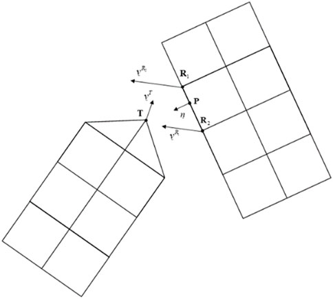
FIGURE 1. Deformable to deformable contact in MSC MARC (Kuijpers, 1994).
The displacement increment of the tied node during contact T in the normal direction to the plane, which contains the point of contact P, is a weighted average of the displacement increments of the retained nodes
Where
The analysis will reveal the following:
and
where
However, nodes are checked for separation only if the convergence criteria are met. For nonlinear contact analysis, the Full Newton-Raphson Method is used to solve the equilibrium equations considering the following equation:
where
Furthermore, the total displacement is
2.2 Flexible multibody simulation
The FE mesh is generated according to the existing gear pairs geometry using solid elements 3D CHEXA Nastran elements (MSC Software Corporation, 2022). A fine mesh is defined in the areas of the tooth where contact is expected to occur as the nonlinear contact can be captured. A much larger mesh was used for the teeth far from the contact zone. The supporting shafts are modeled as infinitely rigid via a central master node rigidly connected to the inner nodes of the gears. The gear backlash is covered by rotating the driving gear to achieve contact at an initial state. Finally, the obtained FE model is imported into MSC MARC Solver for the STE Computation.
A single-stage transmission is considered, where the elasticity of the gears is taken into account, and the quasi-static behavior of the gear pair is evaluated. The meshed bodies are automatically detected, and the driven and driving wheel are identified. The material is assigned, and a new contact interaction is defined. The next step is to set the relative boundary conditions at the wheel’s central nodes 6 DOFs. The applied torque is assigned to the driving gear where the rotational DOF along the axial direction is left unconstrained. While the driven one will get the requested rotation angle
The accuracy of the approach can depend on several factors, e.g., the choice of contact parameters and the mesh density. As with any numerical simulation technique, it is essential to carefully validate and verify the results simulations to ensure that they accurately capture the behavior of the modeled system. For this reason, some numerical test-cases for standard spur and helical gears are considered in the next section.
3 Numerical validation
In this section, a mesh convergence study is first conducted. Subsequently, the STE results from the method described earlier are compared with those obtained from commercial software, namely, ROMAX© (Romax Technology, 2021) and VIBRAGEAR© (Garambois et al., 2017), in its module TERRA (Transmission ERRor Analysis) is proposed. Gears are designed without any microgeometry modification to compare the loaded STE caused by the teeth deflection from the meshing process.
Two important aspects are being tracked in the following comparison. First, the PPTE, with paramount importance, constitutes the amplitude of the excitation being transmitted to the gearbox system. Second, the STE curve shape as it translates the harmonic distribution of the excitation. Under operating conditions, a harmonic order could make an intersection with a specific mode, potentially affecting the analyzed system’s NVH signature. For these reasons, these two parameters need to be accurately identified while studying a gear transmission system.
3.1 Mesh convergence
A convergence study on the FE mesh of the tooth is conducted to establish an efficient multibody simulation. Three mesh cases along the involute profile were examined, corresponding to mesh element sizes of 100, 70, and 50 µm. The goal was to achieve an accurate STE response estimation with minimal computational expense. This procedure is validated using a spur gear pair with the characteristics outlined in Table 1. The mesh generation, consisting of approximately 170,000 nodes and around half a million degrees of freedom, is illustrated in Figure 2A. A detailed view of the teeth region can be seen in Figure 2B.
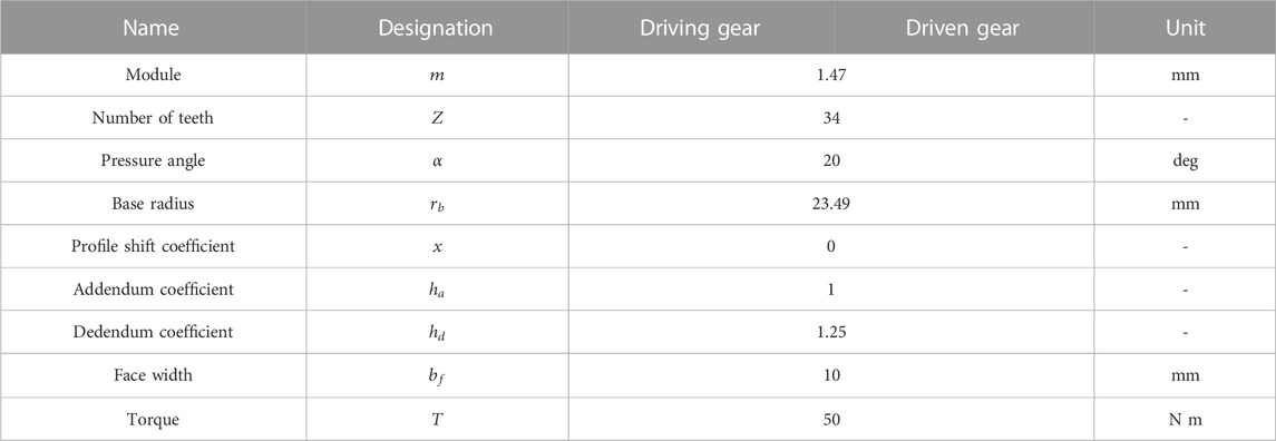
TABLE 1. Macro-geometry parameters of the spur gear pairs.
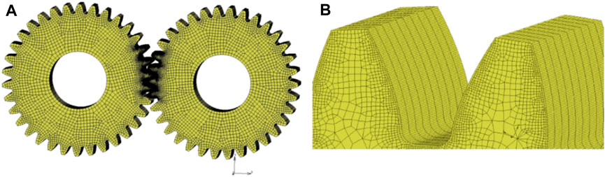
FIGURE 2. (A) Spur gear mesh with hexa-linear element (B) close-up of the tooth mesh with 50 µm element size.
For the nonlinear quasi-static analysis, an output torque of T = 50 Nm was applied. Figure 3A presents the associated STE for different tooth mesh detail levels. The shapes of the curves are nearly identical, indicating a smoother trend with a more refined mesh. All three curves exhibit comparable PPTE and shapes, reflecting similar amplitude and harmonic distributions of the periodic excitations. Notably, as the mesh size reduces from 100 µm to 70 µm to 50 µm, the simulation time over two mesh periods increases sequentially, requiring 1177 s, 2030 s, and 3031 s respectively. Consequently, the 100 µm mesh size was selected as the optimal choice for spur gear cases in terms of involute profile refinement.
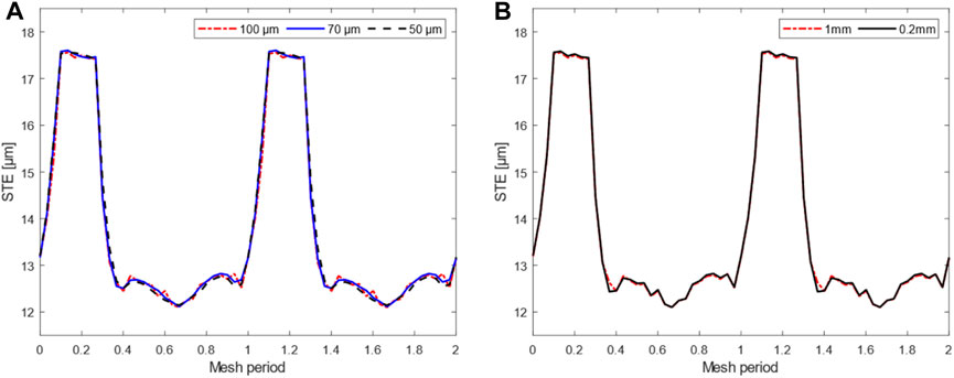
FIGURE 3. Static transmission error with mesh refinement (A) along the involute profile (B) along the face width.
For the selected case, inflations of 10 and 50 layers for the bulk and along the tooth width were compared, corresponding to 1 mm and 0.2 mm lengths. Figure 3B displays consistent results, even though the wall time notably increased to 13449s. This increase in time is attributed to the DOFs nearing 1.5 million in this instance. Therefore, the final mesh chosen for the spur gear case was set with a 100 µm mesh element size along the involute profile and a 1 mm length along the face width.
A similar procedure was applied to the helical gear pair described in Table 2 to derive an accurate yet cost-effective solution, considering the helix angle. Then a 0.5 mm element length along the face width is adopted.
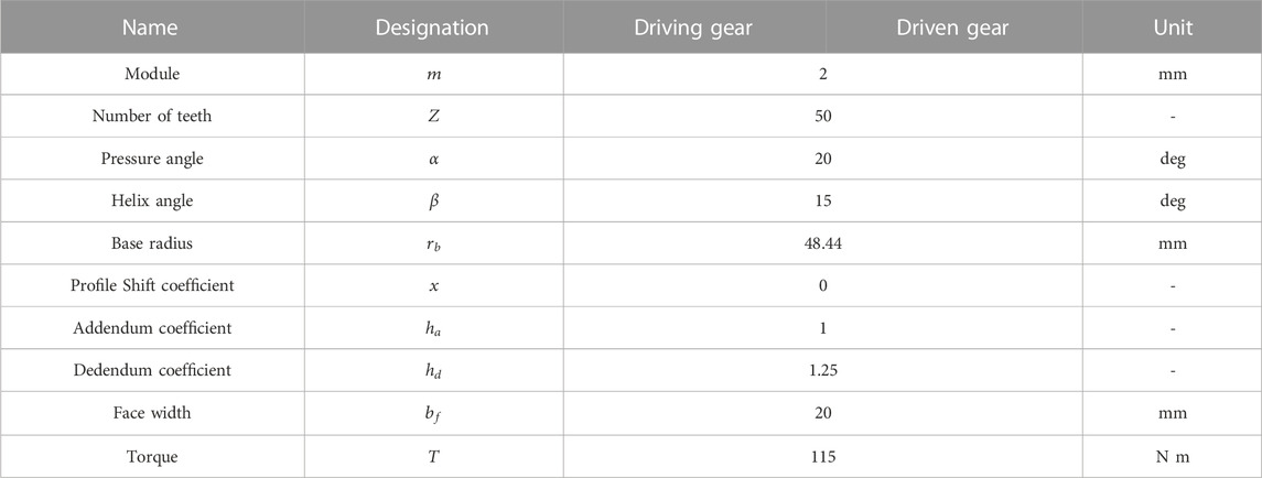
TABLE 2. Macro-geometry parameters of the helical gear pairs.
3.2 Software assumptions
In ROMAX© (Romax Technology, 2021), the microgeometry analysis is based on a thin strip model where the contact teeth are divided into many uncoupled springs across the face width. Figure 4 gives a simplified overview of how this works.
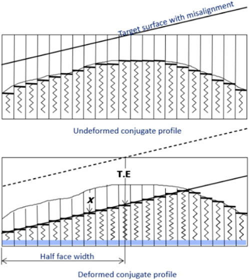
FIGURE 4. Deformed conjugate profile (Romax Technology, 2021).
The first tooth is modeled as a series of uncoupled springs. These springs capture the profile of the micro geometry modifications. In the example below (for simplicity), only one gear is modeled with springs. However, in the ROMAX© software, both teeth are modeled with springs to capture the difference in pinion and wheel gear tooth stiffness.
Considering the backlash, misalignment and torque to calculate the deformed profile, the two gears are bought into contact. This is repeated over the roll angle steps. The microgeometry analysis assumes that the misalignment is constant with the roll step.
The image also shows the absolute value of the TE for one roll step (the Sum of the effects of backlash and deformation). This is calculated at each role step, and the peak-to-peak and harmonics are calculated.
On the other hand, VIBRAGEAR© presents two different ways to calculate the flexibility matrix:
• An analytical model based on the Ritz method, used to calculate the flexibility matrices associated with the contact lines from an analytical model of a thick plate of variable thickness using a Reissner-Mindlin theory.
• From the generation of a finite element mesh allowing the calculation of flexibility matrices using a FE-software. Then, the interpolation of the flexibility matrices associated with the discretized contact lines is created and ready to be scaled with the input data.
3.3 Method validation
A spur and helical gear pair configurations were tested to develop different test conditions in order to better understand the general trend between the results. The macro-geometry parameters and the operating torque are reported respectively in Tables 1, 2 for spur and helical pairs.
Figures 5A, B demonstrate that all software yield comparable peak-to-peak transmission error (PPTE) values for the helical and spur gear cases, respectively, with results reported in Table 3.
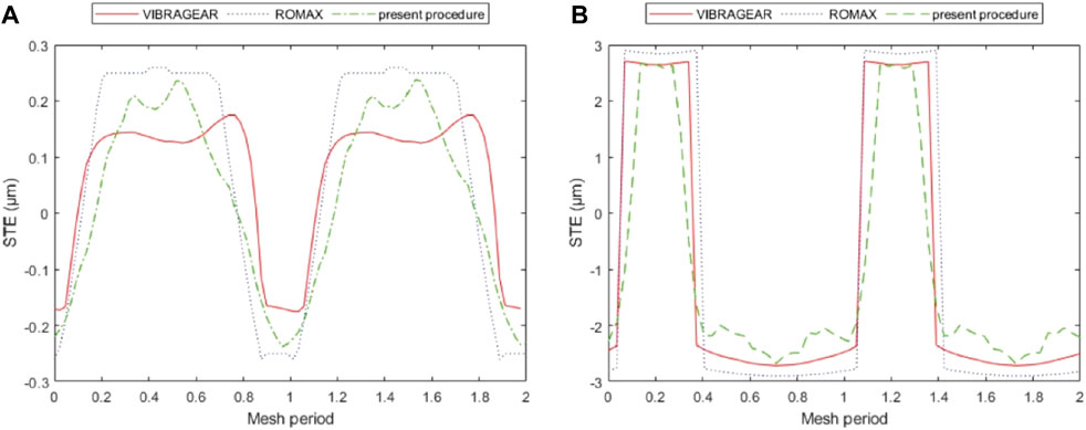
FIGURE 5. STE benchmarking in (A) helical gear case (B) spur gear case.
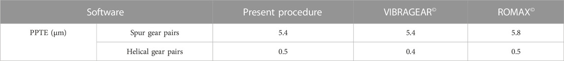
TABLE 3. STE Results comparison between three software methods.
Another comparative criterion is the shape of the curve. ROMAX© and VIBRAGEAR© exhibit similar behavior, with a sudden transition observed from two teeth in contact to one. In contrast, the Multibody FE approach presents a more gradual transition. This difference is attributed to commercial software not directly calculating displacement at a contact point but interpolating it from surrounding nodes, as shown in Figure 6B. Consequently, this approach fails to capture the tip contact at the transition phase, a capability inherent to the multibody method, as shown in Figure 6A. This phenomenon affects the energy distribution between the harmonics and should be considered for a more accurate dynamic response.
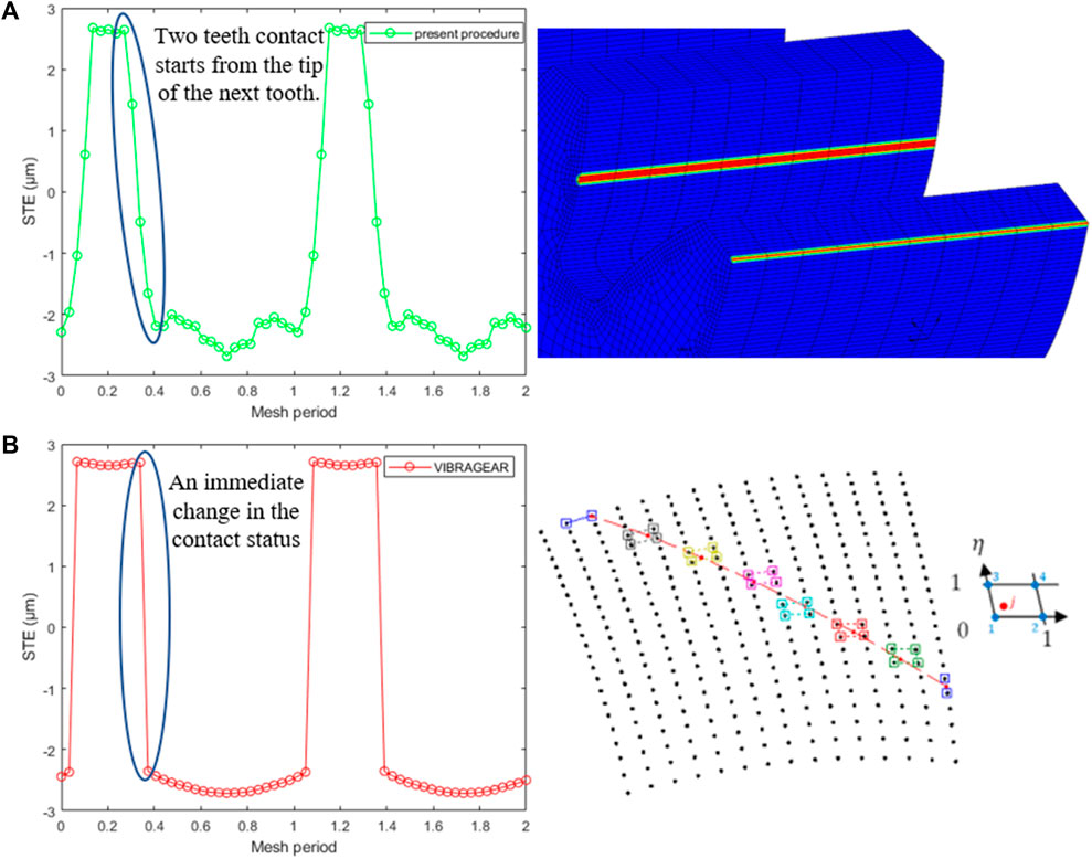
FIGURE 6. Line of contact in (A) MSC MARC Solver (B) VIBRAGEAR ©.
Figure 7 presents an example of the results obtained from the nonlinear FE method near the meshing area. Each image displays the equivalent Von Mises stress distribution for the spur gear pair. When the number of engaging teeth changes from one to two, a reduction in the maximum stress value is noticeable from 1,005 MPa in Figure 7A to 695 MPa in Figure 7B. This variation is due to the time-varying nature of the mesh stiffness. Additionally, this approach allows for a closer look at root stresses, where fluctuations in stress levels can be identified during the contact treatment phase.
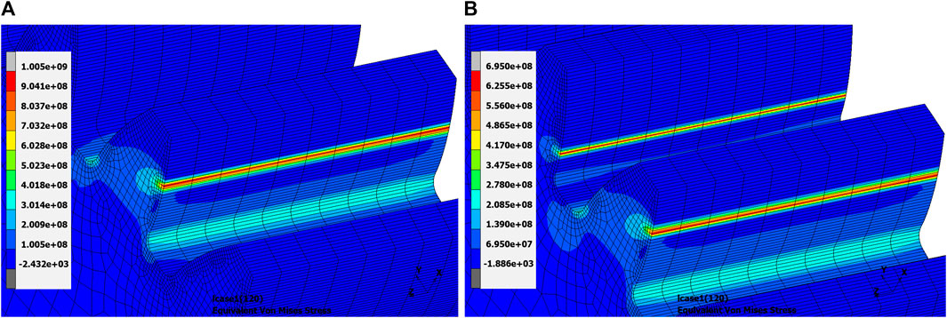
FIGURE 7. Stress distribution in Pa estimated by nonlinear FE simulation using MSC MARC Solver for (A) one tooth in contact (B) two teeth in contact.
Another case study is performed between pairs of spur gears with a different number of teeth, i.e., a reduction ratio
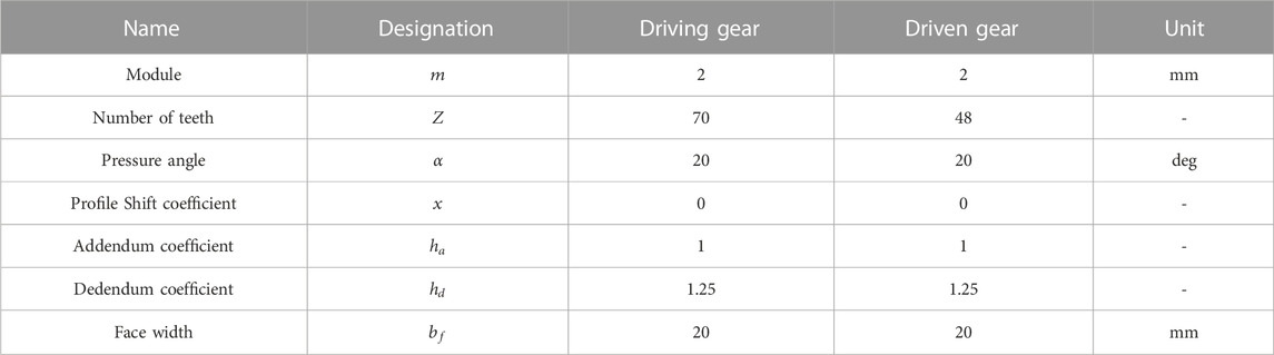
TABLE 4. Macro-geometry parameters of the spur gear pair with.
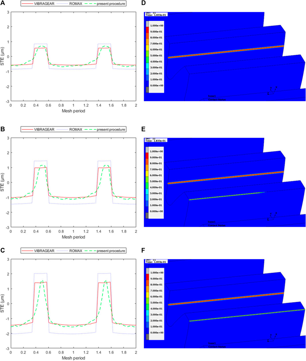
FIGURE 8. Effects of applied torque on the STE evolution [(A): 80 N m, (B) 140 N m, (C) 200 N m] and contact status using the present procedure [(D): 80 N m, (E) 140 N m, (F) 200 N m].
Similar to the earlier observations, ROMAX© and VIBRAGEAR© demonstrated a sudden shift of the STE in this study, with the flexible multibody method indicating a more gradual transition. As shown in Figures 8A–C, this effect becomes increasingly pronounced as torque levels rise. Such a pattern is linked to the theoretical contact lines proposed by ROMAX© and VIBRAGEAR©, which restrict potential contact points to no-load contact points for the corresponding conjugate gear. However, due to load-induced deflection, the tips of the teeth can initiate contact, a phenomenon referred to as “corner contact” in the literature (Langlois et al., 2016).
Figures 8D–F validate this behavior, demonstrating the contact status from the proposed method at the same rotational position across three different torque levels. Figure 8F displays two teeth in contact where the highest torque (200 N m) is applied, while Figure 8D shows a single tooth in contact when subjected to a torque of 80 N m. This increase in the operational contact ratio contributes to the changing shape of the STE curve observed with the present approach.
On the other hand, Figure 9 is showing a comparison between the methods from a peak-to-peak prospective. It is observed that PPTE results obtained with the proposed approach are located in between the ones estimated by ROMAX© and VIBRAGEAR©.
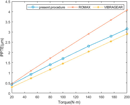
FIGURE 9. Peak-to-peak transmission error comparison for different torque levels T = [20, 50, 80, 100, 140, 175, 200].
The latter methods present a linear increase against the applied load, whereas the multibody simulation shows a nonlinear trend. This aspect is related to the following points:
• The proposed approach presents a contact resolution based on a nonlinear contact analysis. However, an analytical resolution of the contact equations is addressed with ROMAX© and VIBRAGEAR©.
• Unlike the analytical methods, local and global deformations are considered with the present methodology, as no assumptions are made about the contact points’ location. (e.g., in VIBRAGEAR©, the Hertzian contact is linearly integrated into the compliance matrix).
• The proposed method is capable of capturing the “corner contact” phenomenon.
In this validation phase, the STE results obtained from the multibody finite element approach were compared with those generated by ROMAX© and VIBRAGEAR© for standard gear configurations. Despite the higher computational cost of the multibody approach, the necessity of using the proposed method for studying lightweight gears is summarized as follows:
• As lightweight gears are most likely compliant compared to standard ones, a tooth is submitted to higher deflection under load, leading to corner contact at early torque stages.
• When dealing with lightweight gears, using a nonlinear contact analysis instead of an analytical resolution of the contact equations is crucial. This is because modifications to the gear pair can have various effects that may not be accurately captured with an analytical resolution of the contact equations. A nonlinear contact analysis ensures that all possible outcomes are considered, resulting in more accurate results.
• Analytical methods allow the study of the STE over one mesh period. However, most lightweight gears present non-axisymmetric properties, requiring multiple mesh periods to consider the variability of the body stiffness during operating conditions.
• The proposed method enables the acquisition of stress distribution data, which is crucial information, particularly for lightweight gears, where greater complexity in the stress field in the gear body is predicted.
Gathering all these aspects justify the use of the presented method for studying lightweight gears as to be discussed in Section 4.
4 STE of lightweight gears
The study conducted in this section applies the proposed multibody approach to several lightweight gear pairs to highlight the method’s capability. The gear pairs are classified into two lightweight techniques for the previously mentioned spur gear pair (R = 1). The first case is a gear pair with eight holes. The second technique is thin-rim steel gears combined with multi-layered composite material. A high-modulus carbon fiber-reinforced epoxy laminate will be placed in the web part.
4.1 Gear with holes
This section examines the impact of holes in the gear blank on the STE response, using a driven gear with eight holes as an example. Table 5 provides the parameters of the holes. The gear pair achieves a mass reduction of 21%. The torque applied is 50 N m, the same as in the case of standard gears discussed in section 3.
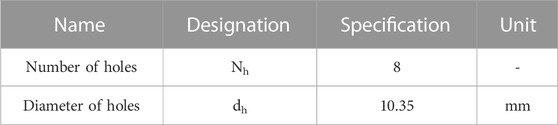
TABLE 5. Holes parameters.
Figure 10A illustrates the STE fluctuations of the standard gear pair throughout a complete rotation. The frequency spectrum, displayed in Figure 10B, highlights the mesh harmonic and its multiples.
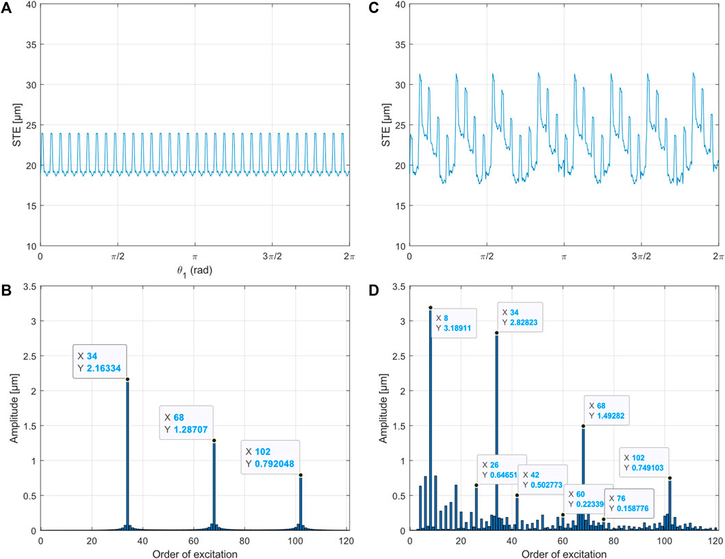
FIGURE 10. Time history and harmonic orders of the STE for standard-driven gear (A, B), and holed-driven gear (C, D).
The presence of the holes significantly alters the curve shape, as shown in Figure 10C, compared to the standard configuration. This material discontinuity introduces additional low-frequency harmonic components. An angular frequency equal to the number of holes in the lightweight gear corresponds to the eighth order of the gear pair rotation.
A similar effect was discussed by Shweiki et al. (Shweiki et al., 2019), where their experimental STE investigation of a lightweight gear with three slots demonstrated a low-frequency contribution corresponding to the third order of the gear pair rotation, equivalent to the number of slots.
Figure 10D corroborates these observations, revealing an eighth-order harmonic with an amplitude surpassing the meshing frequency. Additionally, the harmonic content manifests the presence of sidebands that can be expressed as
Figure 11 illustrates the impact of material removal from the blank on the local and global deformation of the lightweight gear with holes. The absence of material in the direction of the meshing forces results in more significant deflections than when the meshing teeth are close to a web region with no gaps. Furthermore, Figure 11B demonstrates that stresses are more widely distributed, with certain regions exhibiting higher values, such as the hole’s circumference near the meshing area, where concentrated stresses reach 400 MPa, as opposed to 100 MPa in Figure 11A. This discrepancy indicates a stiffer state of the gear and explains the STE curve fluctuations.
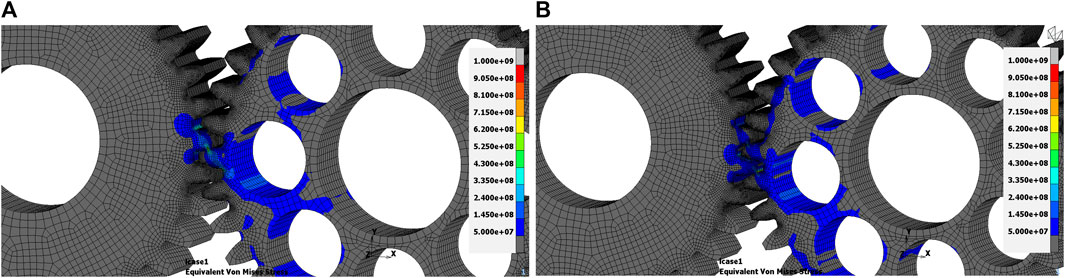
FIGURE 11. Stress distribution in Pa of the holed gear in two angular configurations corresponding to (A) the minimum static deformation and (B) the maximum static deformation.
4.2 Hybrid gears
4.2.1 Description of the hybrid model
In this section, the idea behind the design of the hybrid gears is treated. Beginning with the standard gears previously introduced as a reference. The design is an assembly of two main parts, as presented in Figure 12 with an exploded view:
• Machined standard gear: a thin-rim steel gear where the web part is removed from its thickness.
• Two composite discs will replace the removed steel part: a glued contact is considered between the composite discs and the machined gears. Glued contact ensures no relative sliding or separation between the bodies.
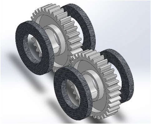
FIGURE 12. Exploded view of spur hybrid gears assembly.
4.2.2 Material properties of the composite discs
The primary objective of this method is to replace the heavy steel with lighter materials in areas exposed to lower loads during the meshing process. This replacement with composite material results in a significant reduction in mass of 42% compared to standard configuration. However, the elastic properties of the laminate must ensure high in-plane and out-of-plane stiffness. Therefore, the composite material used is an epoxy matrix reinforced with high-modulus M46J fibers, as detailed in Table 6, with a fiber volume fraction of 52.6%. The elastic behavior of a unidirectional lamina was calculated using the Chamis Formula and is presented in Table 7, with experimental verification provided in (Catera et al., 2019). The use of unidirectional carbon fiber-reinforced polymer (CFRP) prepregs offers greater design flexibility and permits the investigation of the influence of fiber orientation.
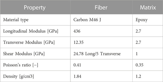
TABLE 6. Fiber and matrix properties (Catera et al., 2019).
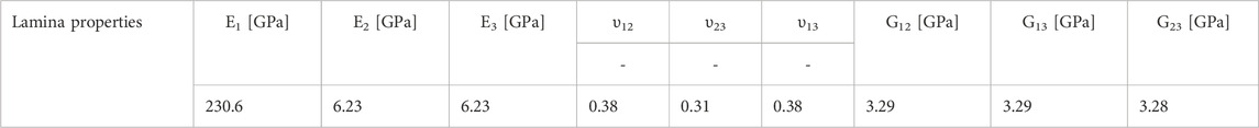
TABLE 7. Unidirectional lamina elastic properties.
As the gears rotate, teeth continue to alternate through the meshing region. Hence, a quasi-isotropic configuration for a more homogeneous response of the composite disc during operating conditions is chosen. The laminate presents ten layers of UD prepreg. The plies’ orientation is the following layup: [0/36/72/108/144]s. Two distinct approaches were employed to model the composite disc:
4.2.2.1 First approach
For this method, the laminate was treated as a single block body, and the equivalent homogenized properties of the elements were applied. These engineering constants were obtained from analytical stress-strain constitutive relations for orthotropic lamina, as detailed in Eqs 10–12 as presented in (Chou et al., 1972).
Where
where
in which
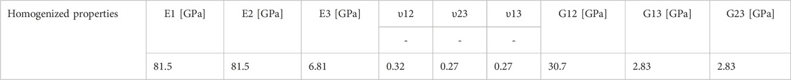
TABLE 8. Homogenized Elastic properties of the laminate.
4.2.2.2 Second approach
In this approach, rather than computing the homogenized properties of the entire thick disc, it was divided into five distinct layers as detailed in the layup sequence. Given that the 0-degree direction aligns with the x-direction in the model, the orthotropic properties of the unidirectional lamina were first allocated to the elements of each layer. Subsequently, these properties were rotated based on their specific orientation in the laminate sequence, using the x-direction as a reference. The symmetric layup was applied to the opposing disc using an analogous procedure. A “glue” contact was assumed between the layers, implying that nodes on one surface are bound to move synchronously with nodes on the adjacent layer’s surface across all degrees of freedom. Figure 13 displays the contact patterns for both the “touching” contact between teeth and the “glue” contact. Both contact types were implemented during the simulation.
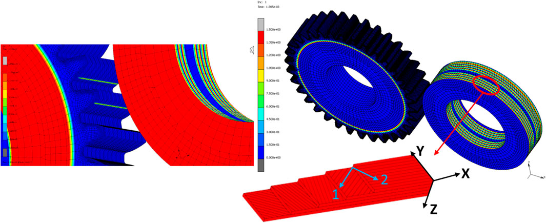
FIGURE 13. Contact patterns and stacking sequence Configuration.
4.2.3 STE of hybrid gears
Figure 14 compares the hybrid gear’s STE curve with the standard gear using the homogenized properties form the first approach. The metal-composite gear shows an increase in the mean TE value, indicating a decrease in overall stiffness. However, the PPTE is moderately increased, which is promising for mass savings.
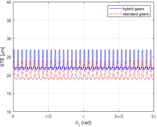
FIGURE 14. STE curves comparison between standard and hybrid gears modeled with homogenized properties.
The second approach considers the proper orientation of each layer in the laminate configuration, assigning unidirectional properties to each layer’s elements. Unlike the first approach, this method highlights the contribution of each ply orientation to the overall body stiffness.
Figure 15A demonstrates a modulation effect of the STE curve that was not captured by the first approach. This modulation exhibits an excitation of order two, which could be due to the effect of fiber orientation causing low-frequency harmonics, as shown in Figure 15B. The TE mean values reach two maxima when the driving gear rotates around 50 and 230 degrees. This indicates the gears have their lowest stiffness at these two angles, resulting in the composite disc being subjected to the lowest stiffness during the meshing process. The degree of modulation varies with the fiber’s orientation.
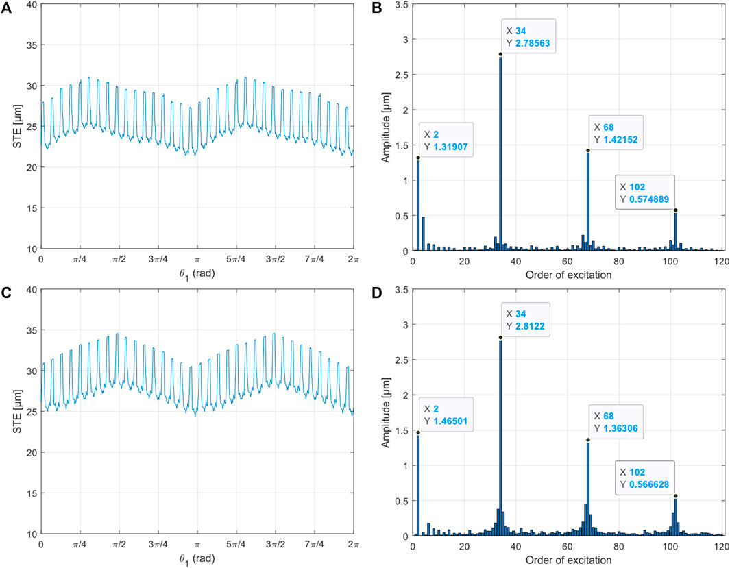
FIGURE 15. Time history and harmonic orders of the STE for hybrid gears with quasi-isotropic laminate (A, B), and unidirectional laminate (C, D).
To simplify the analysis of this effect, a hybrid pair test was performed, employing a composite disc made of unidirectional
Another simulation was conducted using a hybrid gear with quasi-isotropic laminate discs driven by a standard steel gear to observe the effect on STE. The time and frequency domain results are shown in Figures 16A,B, respectively.
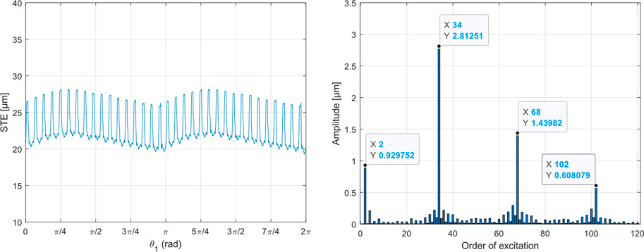
FIGURE 16. Evolution of the STE for a standard gear driving a hybrid one with unidirectional laminate in (A) time domain and (B) frequency domain.
When comparing the hybrid driving hybrid (h-h) and steel driving hybrid (s-h) configurations, it was observed that the modulation peaks occurred at approximately the same gear rotation angle in both cases. However, the s-h set-up presented a lower amplitude of the order two harmonic.
In Section 4.1, the study presented results for a standard gear driving a holed one, with the size and dimensions of the holes chosen to achieve mass properties equivalent to hybrid gears. The availability of a reliable computational procedure allows for basic design considerations. As shown in Figure 17, holed gears exhibit a much higher amplitude of harmonic excitations compared to hybrid wheels. Consequently, hybrid gears are quieter and produce less noise for the same mass reduction, making them a more suitable lightweight strategy.
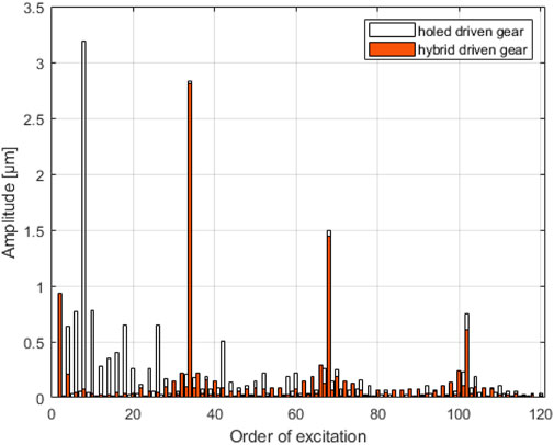
FIGURE 17. Harmonic order comparison: hybrid vs. holed gear pairs.
5 Conclusion
This work has successfully demonstrated the development and application of a robust numerical procedure using a flexible multibody method through the MSC MARC solver to analyze lightweight gear transmission systems, especially those incorporating composites. By addressing the inherent complexities associated with designing gear pairs that utilize such materials, the proposed method contributes significantly to the ongoing advancement of their applications in gear transmission systems.
The present method demonstrated its effectiveness through validation studies with existing commercial software, ROMAX©, and VIBRAGEAR©, showing a good correlation for spur and helical gears. Moreover, the method revealed certain phenomena that were not captured by other techniques. Further application of the numerical procedure to analyze hybrid metal-composite gear pairs and comparison with holed gears provided valuable insights into the time evolution and harmonic components of STE. These results emphasized the benefits of hybrid gears in terms of reduced vibrations and noise for the same mass reduction as holed gears.
Moreover, the study investigated the influence of fiber orientation on STE results by comparing ply arrangements resulting in quasi-isotropic properties of the composite disc with unidirectional laminates. This analysis underscores the importance of considering fiber orientation when designing composite gears for optimal performance.
In summary, the findings of this work contribute to a deeper understanding of the behavior of composite gears and pave the way for further research and development in this area. As part of future work, an experimental study will be conducted to evaluate the static and dynamic behavior of metal-composite hybrid gears. Additionally, future research could explore the effects of various composite material types, manufacturing processes, and environmental factors on the performance of lightweight gears and extend the proposed method to other gear configurations and transmission systems.
Data availability statement
The datasets presented in this article are not readily available because the authors do not have permission to share data. Requests to access the datasets should be directed to WM, bWFzbW91ZGkud2FlbEB1bmluYS5pdA==.
Author contributions
WM conceived and formulated the problem, developed the methodology, analyzed the results, and wrote the paper. GP, FF, and SD supervised the research work as academic supervisors and reviewed the manuscript. J-LW supervised the research as an industry supervisor. All authors contributed to the article and approved the submitted version.
Funding
This project has received funding from the European Union’s Horizon 2020 research and innovation program under the Marie Skłodowska-Curie grant agreement No 860243.
Acknowledgments
The author would like to acknowledge all the Institutions and Partners involved in the LIVE-I project. The authors would like to acknowledge the support provided by ROMAX Technology in making their software available to us under an academic license. The software was used for validation purposes of the presented method in this paper.
Conflict of interest
Author J-LW was employed by Vibratec SA.
The remaining authors declare that the research was conducted in the absence of any commercial or financial relationships that could be construed as a potential conflict of interest.
Publisher’s note
All claims expressed in this article are solely those of the authors and do not necessarily represent those of their affiliated organizations, or those of the publisher, the editors and the reviewers. Any product that may be evaluated in this article, or claim that may be made by its manufacturer, is not guaranteed or endorsed by the publisher.
References
Andersson, A., and Vedmar, L. (2003). A dynamic model to determine vibrations in involute helical gears. J. Sound. Vib. 260, 195–212. doi:10.1016/S0022-460X(02)00920-3
Baud, R. V., and Pederson, R. E. (1929). Load and stress cycle in gear teeth. Mech. Eng. 51, 653–662.
Benaïcha, Y., Mélot, A., Rigaud, E., Beley, J. D., Thouverez, F., and Perret-Liaudet, J. (2022b). A decomposition method for the fast computation of the transmission error of gears with holes. J. Sound. Vib. 532, 116927. doi:10.1016/j.jsv.2022.116927
Benaïcha, Y., Perret-Liaudet, J., Beley, J. D., Rigaud, E., and Thouverez, F. (2022a). On a flexible multibody modelling approach using FE-based contact formulation for describing gear transmission error. Mech. Mach. Theory. 167, 104505. doi:10.1016/j.mechmachtheory.2021.104505
Cai, Y., and Hayashi, T. (1994). The linear approximated equation of vibration of a pair of spur gears (theory and experiment). J. Mech. Des. Trans. ASME. 116, 558–564. doi:10.1115/1.2919414
Cappellini, N., Tamarozzi, T., Blockmans, B., Fiszer, J., Cosco, F., and Desmet, W. (2018). Semi-analytic contact technique in a non-linear parametric model order reduction method for gear simulations. Meccanica 53, 49–75. doi:10.1007/s11012-017-0710-5
Carbonelli, A., Rigaud, E., and Perret-Liaudet, J. (2016). Vibro-acoustic analysis of geared systems—Predicting and controlling the whining noise. Springerbr. Appl. Sci. Technol., 63–79. doi:10.1007/978-3-319-24055-8_5
Catera, P. G., Mundo, D., Gagliardi, F., and Treviso, A. (2020). A comparative analysis of adhesive bonding and interference fitting as joining technologies for hybrid metal-composite gear manufacturing. Int. J. Interact. Des. Manuf. 14, 535–550. doi:10.1007/s12008-020-00647-y
Catera, P. G., Mundo, D., Treviso, A., Gagliardi, F., and Visrolia, A. (2019). On the design and simulation of hybrid metal-composite gears. Appl. Compos. Mater. 26, 817–833. doi:10.1007/s10443-018-9753-6
Chou, P. C., Carleone, J., and Hsu, C. M. (1972). Elastic constants of layered media. J. Compos. Mater. 6, 80–93. doi:10.1177/002199837200600107
chul Kim, S., gon Moon, S., hyeon Sohn, J., jun Park, Y., ho Choi, C., and ho Lee, G. (2020). Macro geometry optimization of a helical gear pair for mass, efficiency, and transmission error. Mech. Mach. Theory. 144, 103634. doi:10.1016/j.mechmachtheory.2019.103634
Chung, W. J., Park, J. H., Yoo, H. G., Park, Y. J., chul Kim, S., hyeon Sohn, J., et al. (2021). Improved analytical model for calculating mesh stiffness and transmission error of helical gears considering trochoidal root profile. Mech. Mach. Theory. 163, 104386. doi:10.1016/j.mechmachtheory.2021.104386
Conry, T. F., and Seireg, A. (1973). A mathematical programming technique for the evaluation of load distribution and optimal modifications for gear systems. J. Eng. Industry 95, 1115–1122. doi:10.1115/1.3438259
Cornell, R. W. (1981). Compliance and stress sensitivity of spur gear teeth. J. Mech. Des. 103, 447–459. doi:10.1115/1.3254939
Du, S., Randall, R. B., and Kelly, D. W. (1998). Modelling of spur gear mesh stiffness and static transmission error. Proc. Inst. Mech. Eng. Part C J. Mech. Eng. Sci. 212, 287–297. doi:10.1243/0954406981521222
Garambois, P., Perret-Liaudet, J., and Rigaud, E. (2017). NVH robust optimization of gear macro and microgeometries using an efficient tooth contact model. Mech. Mach. Theory. 117, 78–95. doi:10.1016/j.mechmachtheory.2017.07.008
Handschuh, R. F., Laberge, K. E., Deluca, S., and Pelagalli, R. (2014). Vibration and operational characteristics of a composite-steel (hybrid) gear. NASA/TM—2014-216646.
Handschuh, R. F., Roberts, G. D., Sinnamon, R. R., Stringer, D. B., Dykas, B. D., and Kohlman, L. W. (2012). Hybrid gear preliminary results - application of composites to dynamic mechanical components. NASA/TM—2012-217630.
Harris, S. L. (1958). Dynamic loads on the teeth of spur gears. Proc. Inst. Mech. Eng. 172, 87–112. doi:10.1243/PIME_PROC_1958_172_017_02
Houser, D. R., and Ozguvent Nevzat, H. (1988). Mathematical models used in gear dynamics-A review. J. Sound. Vib. 121, 383–411. doi:10.1016/S0022-460X(88)80365-1
Kloosterman, G. (2002). Contact methods in finite element simulations. Netherlands: Netherlands Institute for Metals Research.
Kuijpers, A. (1994). Finite element contact analysis: Marc and Dyna3d compared. TU Eindhoven. Fac. Werktuigbouwkd. Afstudeerverslagen.
Langlois, P., Baydu, A., and Owen, H. (2016). Hybrid hertzian and FE-based helical gear-loaded tooth contact analysis and comparison with FE. Gear Technol., 54–63.
Ma, H., Zeng, J., Feng, R., Pang, X., and Wen, B. (2016). An improved analytical method for mesh stiffness calculation of spur gears with tip relief. Mech. Mach. Theory. 98, 64–80. doi:10.1016/j.mechmachtheory.2015.11.017
Neufond, J., Denimal, E., Rigaud, E., Perret-Liaudet, J., and Carbonelli, A. (2019). Whining noise computation of a planetary gear set induced by the multi-mesh excitations. Proc. Inst. Mech. Eng. Part C J. Mech. Eng. Sci. 233, 7236–7245. doi:10.1177/0954406219853313
Opitz, H., and Richards, E. J. (1997). A discussion on the origin and treatment of noise in industrial environments - noise of gears. Philos. Trans. R. Soc. Lond. Ser. A, Math. Phys. Sci. 263, 369–380. doi:10.1098/rsta.1968.0024
Pedrero, J. I. (2022). Analytical model for spur gears with profile modification: simulation of the meshing stiffness, load sharing, and transmission error. Mech. Mach. Sci. 109, 3–26. doi:10.1007/978-3-030-88465-9_1
Rezayat, A., Catera, P. G., Capalbo, C., Cosco, F., and Mundo, D. (2022). Numerical and experimental analysis of the transmission error in hybrid metal-composite gears. Compos. Struct. 298, 116012. doi:10.1016/j.compstruct.2022.116012
Rigaud, E., and Barday, D. (2006). Modelling and analysis of static transmission error. Effect of wheel body deformation and interactions between adjacent loaded teeth.
Rigaud, E., and Barday, D. (2011). Modelling and analysis of static transmission error of gears. Effect of wheel body deformation and interactions between adjacent loaded teeth. J. Phys. A Math. Theor. 44, 11. doi:10.1088/1751-8113/44/8/085201
Rigaud, E. (1998). Interactions dynamiques entre dentures, lignes d’arbres, roulements et carter dans les transmissions par engrenages. France: École centrale de Lyon.
Shweiki, S., Palermo, A., and Mundo, D. (2017). A study on the dynamic behaviour of lightweight gears. Shock Vib. 2017, 1–12. doi:10.1155/2017/7982170
Shweiki, S., Rezayat, A., Tamarozzi, T., and Mundo, D. (2019). Transmission Error and strain analysis of lightweight gears by using a hybrid FE-analytical gear contact model. Mech. Syst. Signal Process. 123, 573–590. doi:10.1016/j.ymssp.2019.01.024
Bogetti, T. A., Hoppel, C. P. R., and Drysdale, W. H., Three-dimensional effective property and strength prediction of thick laminated composite media, aberdeen proving ground, MD U.S. Army Res. Lab. Maryland, (1995).
Vijayakar, S. (1991). A combined surface integral and finite element solution for a three-dimensional contact problem. Int. J. Numer. Methods Eng. 31, 525–545. doi:10.1002/nme.1620310308
Wang, J., and Howard, I. (2005). Finite element analysis of High Contact Ratio spur gears in mesh. J. Tribol. 127, 469–483. doi:10.1115/1.1843154
Weber, C., and Banaschek, K. (1953). Formanderung und Profilrucknahme bei Gerad-und Schragverzahnten Antriebstechnik. Vieweg 11.
Weber, C., Banaschek, K., and Niemann, G. (1955). Formänderung und profilrücknahme bei gerad-und schrägverzahnten rädern. Wiesbaden: Vieweg.
Wu, S., Zuo, M. J., and Parey, A. (2008). Simulation of spur gear dynamics and estimation of fault growth. J. Sound. Vib. 317, 608–624. doi:10.1016/j.jsv.2008.03.038
Yang, H., Shi, W., Chen, Z., and Guo, N. (2022). An improved analytical method for mesh stiffness calculation of helical gear pair considering time-varying backlash. Mech. Syst. Signal Process. 170, 108882. doi:10.1016/j.ymssp.2022.108882
Zhan, J., Fard, M., and Jazar, R. (2017). A CAD-FEM-QSA integration technique for determining the time-varying meshing stiffness of gear pairs. Meas. J. Int. Meas. Confed. 100, 139–149. doi:10.1016/j.measurement.2016.12.056
Zheng, X., Luo, W., Hu, Y., He, Z., and Wang, S. (2022). Analytical approach to mesh stiffness modeling of high-speed spur gears. Int. J. Mech. Sci. 224, 107318. doi:10.1016/j.ijmecsci.2022.107318
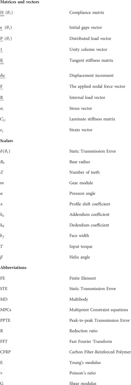
Nomenclature
Keywords: gear transmission error, flexible multibody modeling, lightweight gears, finite element analysis, contact formulation
Citation: Masmoudi W, Wojtowicki J-L, Petrone G, Franco F and De Rosa S (2023) Evaluating lightweight gear transmission error: a novel nonlinear finite element approach using direct constraint contact algorithm. Front. Mech. Eng 9:1228696. doi: 10.3389/fmech.2023.1228696
Received: 25 May 2023; Accepted: 18 September 2023;
Published: 13 October 2023.
Edited by:
Shuvodeep De, Oak Ridge National Laboratory (DOE), United StatesReviewed by:
Hui Ma, Northeastern University, ChinaWrik Mallik, University of Glasgow, United Kingdom
Copyright © 2023 Masmoudi, Wojtowicki, Petrone, Franco and De Rosa. This is an open-access article distributed under the terms of the Creative Commons Attribution License (CC BY). The use, distribution or reproduction in other forums is permitted, provided the original author(s) and the copyright owner(s) are credited and that the original publication in this journal is cited, in accordance with accepted academic practice. No use, distribution or reproduction is permitted which does not comply with these terms.
*Correspondence: Wael Masmoudi, bWFzbW91ZGkud2FlbEB1bmluYS5pdA==