 Shervin Azadi
 Ali Abjadi1*
- 1Department of Mechanical Engineering, South Tehran Branch, Islamic Azad University, Tehran, Iran
- 2Department of Mechanical Engineering, East Tehran Branch, Islamic Azad University, Tehran, Iran
Improving the performance of heat sinks is very important in the development of cooling systems. In this study, the use of a novel combination method [magnetic field impingement jet (MF-IJ)] to improve the convective heat transfer coefficient in a designed heat sink is numerically investigated. To model heat transfer, a steady three-dimensional computational fluid dynamics (CFD) approach is employed. Numerical results including velocity and temperature contours, as well as the distribution of wall temperature of the heat sink and also the convective heat transfer coefficient are analyzed. The results show that the use of ferrofluid (Fe3O4/water) flow with an external magnetic field alone increases the heat transfer coefficient by 10%, while the use of an air impingement jet with pure water and without a magnetic field increases it by 22.4%. By using the MF-IJ method, a 32% enhancement of heat transfer coefficient is achieved compared to the case of pure water flow and without MF-IJ. Based on results, at a Reynolds number of 600, by applying the magnetic field intensities of 400, 800, and 1600 G, the average heat transfer coefficient increases by 5.35, 11.77, and 16.11%, respectively. It is also found that the cooling of the heat sink and temperature distribution is improved by increasing the Reynolds number and the inlet mass flow rate of the impingement jet. For instance, at z = 0.02 m, the application of an impingement jet with mass flow rates of 0.001, 0.004, and 0.005 kg/s results in a respective decrease of 0.36, 1.62, and 1.82% in wall temperature. The results of the current study suggest that the combination method of MF-IJ can be utilized for heat sinks with high heat flux generation as a flow control device.
1 Introduction
The development of cooling systems in industries is of great importance (Pereira et al., 2015; Johnson and Go, 2016). Among them, Plate-fin heat sinks have broad applications in various industries to dissipate heat. Researchers have extensively studied and developed the use of plate-fin heat sinks in combination with jet and fan cooling systems (Bar-Cohen, 1993). Numerous investigations have been carried out to examine the performance of plate-fin heat sinks with impingement jet flow. However, heat sinks have limitations such as bulkiness, but they are still widely used and effective for cooling electronic devices. Moreover, Considerations for efficient thermal management are crucial when using heat sinks.
Kotb et al. (2023) performed an experimental study on the jet impingement cooling of a flat plate. Biber (1997) conducted a numerical investigation to identify the effective parameters in the channels of a plate-fin heat sink and presented a correlation for the average Nusselt number. Kondo et al. (1998) investigated a plate-fin heat sink with six zones in a semi-empirical zonal manner and confirmed the values of thermal resistance and pressure drop. Forghan et al. (2001) conducted studies on two different types of heat sinks with plate fin, and pin fin, and found that for low air velocities, the thermal performance of the plate-fin heat sink was lower compared to the pin-fin heat sinks. Jang et al. (2003) performed an experimental study to examine the impact of an impingement jet on a heat sink equipped with parallel pin-fins. Their findings revealed that incorporating parallel pin-fins into an impingement jet system can enhance heat transfer by as much as 30%. Li et al. (2009) carried out a combined numerical and experimental investigation to explore how parameters such as fin width, fin height, and jet distance impact the thermal performance of plate-fin heat sinks. Their research revealed that these factors can exert a considerable influence on the thermal performance of the heat sinks. Cheong (Wong and Indran, 2013) studied the effect of a fillet profile on the thermal performance of the heat sink and observed adding a fillet profile at the bottom of the plate-fin heat sink can increase the thermal performance by up to 13%. Byon (2015) examined the effect of effective parameters in increasing the heat transfer of an aluminum heat sink under the influence of an impingement jet with uniform pumping power and provided an experimental correlation to predict the Nusselt number as a function of the pumping power and the dimensionless distance of the jet to the heat sink. Naphon et al. (2019) conducted a numerical and experimental analysis of the flow and heat transfer properties of nanofluid jets in microchannel heat sinks. This study utilized computational fluid dynamics and neural network optimization algorithms to create a model that could analyze both heat transfer and pressure drop in microchannel heat sinks. Gan et al. (2020) proposed a geometry that included inlet and outlet microchannels to improve the heat transfer of microchannel heat sinks using impingement jets. Researchers detected the proposed geometry increased heat transfer by 17.5% and decreased pressure drop by 22%. Froissart et al. (2021) used a heat sink with a humped cone structure and applied an impingement jet to it to increase heat transfer by 10% compared to a flat heat sink and reduce pressure drop. Pandey et al. (2022) conducted an experimental study on the thermal performance of a copper heat sink featuring two types of parallel microchannel heat sinks and pin-fin heat sinks. The investigators discovered that the thermal resistance decreased with increasing pumping power for both heat sink models. Additionally, they found that the pressure drop of the parallel heat sink was higher than that of the pin-fin heat sink.
Numerous researchers have explored the utilization of a magnetic field to enhance heat transfer (Jalili et al., 2023a; Jalili et al., 2023b; Jalili et al., 2023c; Sadighi et al., 2023; Sadighi et al., 2023; Sadighi et al., 2022a). A flow of ferrofluid is made up of magnetic nanoparticles and a base fluid, which could be oil or water. When subjected to an external magnetic field, these two components combine to create a fluid with improved magnetic characteristics (Bailey, 1983). The magnetic nanoparticles used in the studies are typically Fe3O4, Al2O3, CuO, and TiO2, with water being the most common base fluid. It should be noted that in some studies, combinations of different nanoparticles have been used to improve the thermal conductivity of the ferrofluid. Ferrofluids are widely used in the heat sink and electronics industries due to their remarkable ability to regulate and enhance temperature through the application of an external magnetic field (Bahiraei and Hangi, 2013). In addition, when exposed to a magnetic field, ferrofluids demonstrate an increase in thermal conductivity. This characteristic makes them even more valuable in the heat sink and electronics industries where efficient heat dissipation is crucial (Karimi et al., 2015). In recent years, there have been numerous studies on the use of ferrofluids with an external magnetic field to control and enhance the thermal performance of heat sinks. Selvakumar and Suresh (2012) conducted an experimental study on the increase of heat transfer in a heat sink, achieving a 29.63% increase in heat transfer compared to DI water. Zamzamian et al. (2011) conducted an experimental study on the enhancement of the heat transfer coefficient using Al2O3/EG and CuO/EG nanofluids in a plate heat exchanger under turbulent flow. Li and Xuan (2009) experimentally investigated the characteristics of heat transfer in a magnetic fluid flow with Fe3O4/water around a heated fine wire under the influence of an external magnetic field. This study found an enhanced heat exchange between the wire and ferrofluid in the presence of a non-uniform magnetic field. (Ashjaee et al., 2015). investigated the effect of a magnetic field on forced convection heat transfer and pressure drop of Fe3O4 nanofluid in a microchannel heat sink. The results showed a 38% increase in heat transfer compared to the case without a magnetic field. Bahiraei and Hangi (2016) conducted a numerical investigation of the hydrothermal characteristics that affect the heat transfer of a magnetic nanofluid in a toroidal loop with two heat sources and heat sinks under the influence of a magnetic field. Bezaatpour and Goharkhah (2019) numerically investigated the effect of an external magnetic field on a porous fin heat sink with a ferrofluid flow consisting of Fe3O4 and water as the base fluid. This study found that high values of the volume fraction of the nanofluid, the porosity of the fins, and intensity of the magnetic field, cause an increased amount of heat transfer. Zhong et al. (2021) conducted a numerical investigation of the ferro-nanofluid flow within a porous ribbed microchannel heat sink using single-phase and two-phase approaches in the presence of a uniform magnetic field. Researchers observed parameters such as porosity percentage, Reynolds number, and Hartmann number have a direct relation with increasing heat transfer coefficient. El-Shorbagy et al. (2021) numerically investigated the effect of fin thickness on the mixed convection of a hybrid nanofluid (Al2O3/CuO) exposed to a magnetic field to enhance heat sink efficiency. The study revealed that CuO nanoparticles increase heat transfer more than Al2O3, and were able to investigate the effect of a hybrid nanofluid on the heat sink.
Sadighi et al. (2022b) analytically solved the MHD micropolar fluid flow and mixed convection characteristics using entropy production analysis of a sheet that is stretched with an inclined porous surface. Jalili et al. (2023d) carried out a numerical investigation of the magnetic field effect on the thermal behavior of a microchannel heat sink. This study used the Koo-Kleinstreuer model (KKL correlation) to obtain the viscosity and effective thermal conductivity of the nanofluid. The results showed that the magnetic field has a direct relation with the Nusselt number, indicating that the heat transfer rate increases with increasing magnetic field intensity. Active flow control techniques such as plasma actuators (Mirzaei and TaleghaniShadaram, 2012; Taleghani et al., 2012; Salmasi et al., 2013; Mohammadi and Taleghani, 2014; Taleghani et al., 2018), pulse blowing (Abdolahipour et al., 2021; Abdolahipour et al., 2022a; Abdolahipour et al., 2022b), surface acoustic waves (Sheikholeslam Noori et al., 2020a; Sheikholeslam Noori et al., 2020b; Noori et al., 2020; Sheikholeslam Noori et al., 2021; Taeibi Rahni et al., 2022), etc. are rapidly developing in fluid mechanics and aerodynamics. Desired goals in engineering can be achieved using Flow control such as lift enhancement, drag reduction, heat transfer enhancement, etc.
A review of past studies on cooling using heat sinks, especially in the electronics industry, shows that the main challenge is to achieve a uniform and low temperature distribution on the surface of the heat sink body, as well as a high convective heat transfer coefficient. With the increase in the use of electronic devices and subsequent heat generation, it is more important than ever to study and investigate new cooling methods in heat sinks. Advanced cooling technologies can have better thermal performance for heat sink cooling and as well as the potential to reduce greenhouse gas emissions and mitigate the environmental impact of cooling systems. However, despite the numerous studies conducted on heat sink cooling methods, the simultaneous effect of two flows with different regimes on the cooling of heat sinks has not been fully explored. Therefore, the main objectives and novelty of present work are as follows:
• Development of a new geometry for heat sink including the microchannel and plate fins.
• Obtaining the maximum improvement of the convective heat transfer coefficient of the designed heat sink by the proposed combination method of magnetic field and impingement jet (MF-IJ) as a flow control device.
• Obtaining the maximum improvement of the wall temperature distribution of the designed heat sink under the MF-IJ method.
2 Problem description
The objective of this section is to create a computational fluid dynamics (CFD) model that can analyze heat transfer in a heat sink when subjected to cooling with the proposed method (MF-IJ). The aim is to investigate various parameters including wall temperature, heat transfer coefficient, Reynolds number of the nanofluid, and contour of temperature and velocity distribution of the designed heat sink. The heat sink being analyzed is made of aluminum and has 10 parallel pin-fins on the top and 5 circular microchannels at the bottom of it. Moreover, the thickness of the fins and the distance between them are both constant at 1 and 3.3 mm, respectively, along the entire length of the heat sink. The length, width, and height of this designed heat sink respectively are 40, 40, and 20 mm used in numerical simulation and shown in Figure 1A. All of the dimensions of the proposed design are condensed in Table 1.
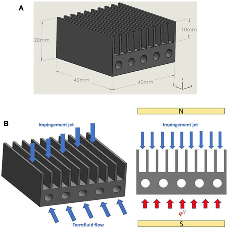
FIGURE 1. (A) The geometrical model of the designed heat sink. (B) Schematic of the flow direction of impingement jet and ferrofluid flow.

TABLE 1. Dimensions of the designed heat sink (mm).
As illustrated in Figures 1A, B uniform impingement jet flows along the Y-direction and strikes the top of the heat sink, after which it flows in the Z-direction and exits the heat sink. Furthermore, a ferrofluid (Fe3O4/water) flows through the microchannels of the heat sink simultaneously.
In this study, the designed heat sink was investigated under two uniform heat fluxes: 66,000 W/m2 and 18,750 W/m2, respectively, that were applied from the bottom of the heat sink. The rest of the surfaces were assumed to be insulated. Moreover, according to the reference (Ashjaee et al., 2015) assumed that the heat sink is located between the air gap of a U-form electromagnet. As shown in Figure 1B a uniform external magnetic field in Y- direction is designed at the core of the air gap and as well as, this external magnetic field applies with various intensities in the direction vertical to the orientation of moving the ferrofluid that flows in the Z direction.
3 Governing equations and boundary conditions
In this study, there are two flows with different regimes, therefore, in this section, the governing equations and boundary conditions of both regimes have been presented.
3.1 Impingement jet flow
To investigate of air impingement jet flow in the heat transfer process, it is requirement to verification the continuity, momentum, and energy equations with the assistance of the following assumptions:
1. The heat transfer is considered conjugate and three-dimensional.
2. The air flow is assumed to be steady state, in a turbulent regime, and incompressible.
3. Gravity and heat loss terms, are ignored.
4. All properties of the heat sink body are assumed to be constant.
5. All properties of the air are depending on the mean temperature which is expressed according to the following equation:
Where
The continuity equation can be expressed in the following form:
Navier-Stokes equations in x, y, and z directions in Cartesian coordinates are given as followings:
The energy equation is expressed as follows:
In this equation,
3.2 Turbulent flow modeling
The Reynolds number for the impingement jet at the highest mass flow rate in this designed heat sink is approximately 1,550, it is in the turbulent range, which is above the critical Reynolds number of 1,400. Furthermore, the Reynolds number is calculated according to the following equation (Fox et al., 2020):
Where
In between the types of RANS turbulent models, the two-equation k-ε model introduced by Launder and Spalding is known as a standard turbulent model today (Spalding, 1974). RANS equations are derived by replacing the Reynolds decomposition terms in the conservation of momentum equations.
Studies have shown that the realizable k-ε model has the best performance in between all sorts of the k-ε model for flows with separation as well as complex secondary flows, and therefore, in this study, this model is used to model the impingement jet flow. The transport equations for the k and ε in the Realizable model are as equations (8) and (9) (Singh et al., 2021):
Where
3.3 Ferrofluid flow
Continuity, momentum, and energy equations assuming a 3D, laminar, incompressible, homogeneous and steady-state form, for fluid and solid regions are as follows (Bezaatpour and Goharkhah, 2019):
The energy equation of the fluid region is written as follows:
Where
Considering that in this study, the microchannels of ferrofluid flow are solid, the porosity in Eq. 11 is 0. Additionally, the third and fourth terms on the right-hand side of Eq. 11 represent the Darcy and Forchheimer terms respectively, and the last term represents the magnetic volume force. Since the fluid and solid regions are in thermal equilibrium, the energy equation for the solid region can be expressed as follows (Bezaatpour and Goharkhah, 2019).
3.3.1 The computing of the magnetic volume force
In this study, the Fe3O4/water is used as a ferrofluid, therefore maxwell equations can be written as (Xie et al., 2021):
The following relation is available from (Bezaatpour and Goharkhah, 2019):
Where
According to (Ganguly et al., 2004) it is possible that the magnetization vector is compliant with the magnetic field, for that reason:
Considering that the variation of
As a result, the magnetic volume force (kelvin body force) is obtained from Bezaatpour and Goharkhah (2019):
The first term in the magnetic volume force equation is similar to the pressure term in the momentum equation. According to Ref. (Ganguly et al., 2004), when a heat sink is placed at the center of the electromagnet air gap, there is a uniform element in the Y-direction (Selvakumar and Suresh, 2012). As a result, the magnetic volume force equation can be written as Eq. 20 (Bezaatpour and Goharkhah, 2019).
3.4 Boundary conditions
The air impingement jet flow with a constant inlet temperature of 298 K and inlet mass flow rates of 0.001, 0.003, 0.004, and 0.005 kg/s entrance the plate-fins, and simultaneously ferrofluid flow with a constant inlet temperature of 298 K and uniform velocity flow into the microchannels of ferrofluid.
The uniform heat flux from the bottom surface of the heat sink is 66,000 W/m2 and 18,750 W/m2, Additionally, the no-slip condition exists between the fluid and solid body of the heat sink, hence:
The walls of the heat sink are assumed to be insulated:
In this study, the properties of aluminum and Fe3O4 particles are written in Table 2. (Bezaatpour and Goharkhah, 2019).
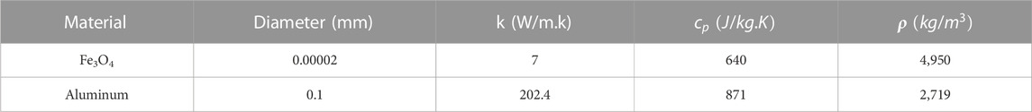
TABLE 2. Properties of Aluminum and Fe3O4 particles.
3.5 Thermophysical properties of the nanofluid
In this study, the nanofluid consists of water and iron oxide (Fe3O4). According to Ref. (Xuan and Roetzel, 2000), for a two-phase mixture, the properties of the nanofluid as a function of the nanoparticle volume fraction and temperature can be written as follows:
Moreover, for volume fractions less than or equal to 2%:
And as well, for volume fraction greater than 2% (Bezaatpour and Goharkhah, 2019):
The thermal conductivity of nanofluid is mainly due to Brownian motion, which is the random movement of particles in a fluid. Brownian motion in nanofluids causes micro-mixing, thus micro-mixing effect enhances the thermal conductivity of the nanofluid by increasing effective contact between the nanoparticles and the fluid molecules, which facilitates heat transfer (Koo and Kleinstreuer, 2004). Therefore, from (Koo and Kleinstreuer, 2004)
Where,
4 Numerical modeling and validation of the numerical method
In this study, the grid independency of numerical results of the impingement jet flow was investigated for the maximum input mass flow rate of air. The appropriate mesh was selected, and numerical simulations were performed for other mass flow rates, and ultimately the validation of the numerical results was achieved.
The energy and momentum equations were discretized using the second-order upwind method (Jazmi et al., 2021), and the SIMPLE algorithm was used for pressure-velocity coupling (Mohammadzadeh et al., 2018). In this research, y+ < 96, and scalable wall functions are used. These wall functions are designed to prevent the degradation of standard wall functions when the grid is refined to a level where y+ < 30. By doing so, the scalable wall functions produce reliable and consistent results for grids of any level of refinement. For grids that are not as refined, with y+ > 30, the standard wall functions remain unchanged. The aim of using scalable wall functions is to ensure that the log law is integrated with the standard wall functions approach (ANSYS Fluent 17.2, 2016).
To validate the numerical results of the impingement jet, a mass flow rate of 0.00433 kg/s was considered. To check the grid independence of the impingement jet, primary simulations were carried out using grid sizes of 184,000, 257,588, 372,000, 534,660, 780,800, 1,108,080, and 1,550,000. The grid sizes were selected such that the skewness, smoothness, aspect ratio, and orthogonality were within the appropriate range. Additionally, to enhance the accuracy of the numerical results, a bias factor of 1.4 was applied to the meshes near the walls.
The thermal resistance and pressure drop results for various grid sizes are presented in Figure 2A Based on these results, a grid size with 780,800 elements was selected to reduce computation time for the validation of the impingement jet flow. The current study results for the validation of the impingement jet flow are compared with the experimental results of (Kim et al., 2009) and the numerical results of Hussain et al. (2019). Figures 2B, C depict the pressure drop and thermal resistance for different mass flow rates, respectively. Based on Figure 2B, the pressure drop increases as the inlet mass flow rate rises, which results in increased friction and losses due to the increase in the Reynolds number. Moreover, as shown in Figure 2C, the thermal resistance decreases with an increase in the mass flow rate. As can be seen, the maximum errors of pressure drops and thermal resistance are 5.6% and 7.2%, respectively, compared to the experimental results of (Kim et al., 2009).
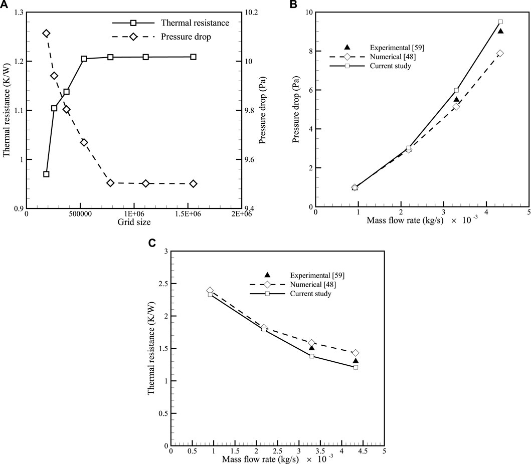
FIGURE 2. (A) Comparison of mesh size changes based on thermal resistance and pressure drop. (B) Validation of CFD results for pressure drop at various mass flow rates. (C) Validation of CFD results for thermal resistance at various mass flow rates.
To validate the numerical method for simulation of ferrofluid flow under the influence of a magnetic field, the grid independence of the model was investigated using computational grids of 427,047, 647,610, 1,091,742, and 1,550,255 grid sizes, as shown in Figure 3A. The results for the bottom wall temperature along the channels, which were subjected to a heat flux of 66,000 W/m2, φ = 2%, and Reynolds number of 830 are presented in Figure 3A. The results show that the grid with 1,091,742 and 1,550,255 elements are close to each other. Therefore, the grid with 1,091,742 elements will be used for the validation of the ferrofluid flow under the influence of a magnetic field. The pressure drop values for different Reynolds numbers and the local convective heat transfer coefficient along the channels were compared with the experimental results of Ashjaee et al. (2015), as shown in Figures 3B, C, respectively. The results indicate a maximum discrepancy of 7.83% for pressure drop and 6.75% for the local convective heat transfer coefficient. Therefore, it can be concluded that there is a good agreement between the numerical results of the current study and the experimental results of Ashjaee et al. (2015).
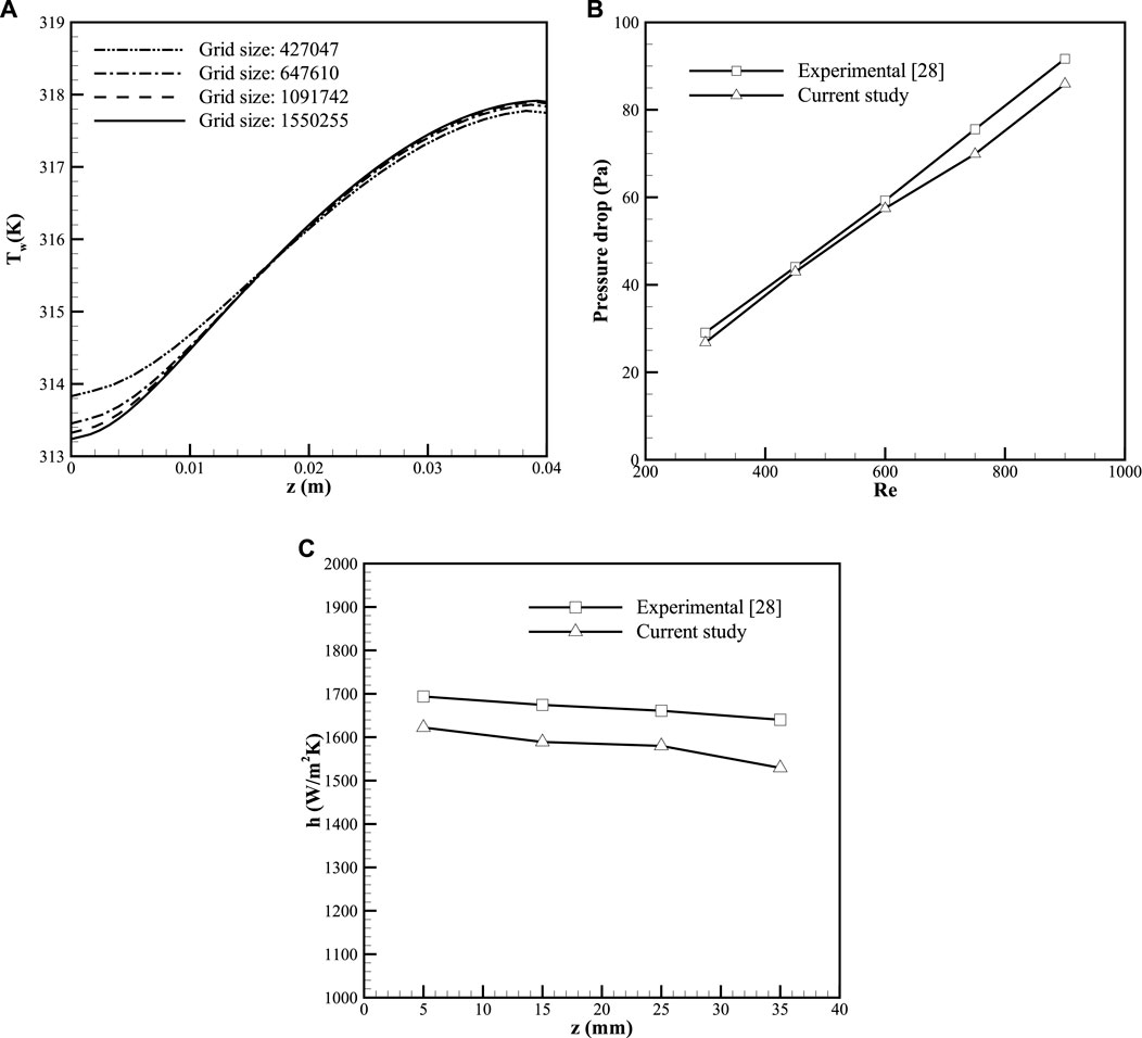
FIGURE 3. (A) Bottom wall temperature variation of the heat sink along the channels. (B) Comparison between experimental and numerical results of pressure drop at B = 800 G and φ = 2%. (C) Comparison between experimental and numerical results of local convective heat transfer coefficient at B = 1,200, Re = 600, and φ = 3%.
5 Mesh generation
In this section, a coupled algorithm was used to solve the pressure-velocity coupling for the numerical simulation of a heat sink under the effect of MF-IJ. The equations of momentum and energy were discretized using the second-order upwind method, and the residual values for the continuity, momentum, and energy equations were set to 10−4, 10−6, and 10−9, respectively. To investigate the grid independence of the numerical results for the heat sink under the effect of MF-IJ, the variations of the local convective heat transfer coefficient for grid sizes 325,280, 580,678, 1,139,856, and 2,129,781 were obtained, as shown in Figure 4A, for the maximum Reynolds number (Re = 900) of the nanofluid. Based on Figure 4A, it can be observed that the results obtained for the grid size of 1,139,856 and 2,129,781 elements are close to each other. Therefore, to reduce the computation time the grid size with 1,139,856 elements will be used for the rest of the simulations of the heat sink under the effect of MF-IJ.
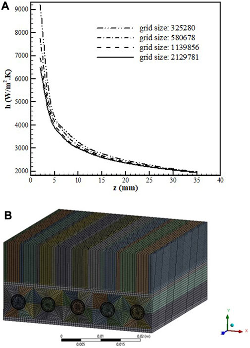
FIGURE 4. (A) Grid study of local convective heat transfer coefficient along the channels at heat flux = 18,750 W⁄m2, Re = 900, φ = 3%, B = 1200 G, and
Figure 4B shows by hybrid mesh with structured and unstructured meshes was used to mesh the designed geometry under the effect of MF-IJ. In this geometry, due to the high gradient variation of temperature and velocity, mesh refinement was applied with a bias factor of 1.4 near the walls. This approach was adopted to ensure accurate capture of the flow and temperature fields near the walls.
6 Results and discussion
In this section, numerical simulations have been carried out for heat flux values of 18,750 W/m2 and 66,000 W/m2. In addition, a comparison has been made between the convective heat transfer coefficient of TC1 with TC2, TC3, and TC4. The details of these Test cases are shown in Table 3. Based on the numerical results presented in Figure 5, it can be concluded that the cooling of the heat sink is done at a higher rate in case TC2 than in case TC1.
TABLE 3. The studied test cases.
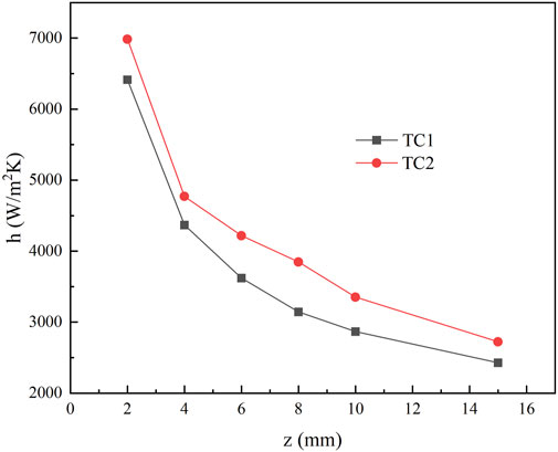
FIGURE 5. The local convective heat transfer coefficient of TC1 and TC2 along the heat sink length at a heat flux of 18,750 W/m2.
The maximum enhancement of the local convective heat transfer coefficient in case TC2 was obtained at 22.4% relative to TC1. The comparison between the results of TC1 and TC2 revealed that the impingement jet increases the velocity gradient in the plate-fins region of the heat sink, which led to a more effective exchange of heat between the air and the heat sink, resulting in the heat transfer coefficient enhancement relative to TC1.
The effect of using a magnetic field in the designed heat sink, is presented in Figure 6. As can be seen, the maximum increase in the local convective heat transfer coefficient in comparison to heat sink cooling using the case of TC3 versus the case of TC1 is almost 10%. The reason for the increase in heat transfer rate is that the magnetic field induces fluid motion, which increases the mixing in the fluid.
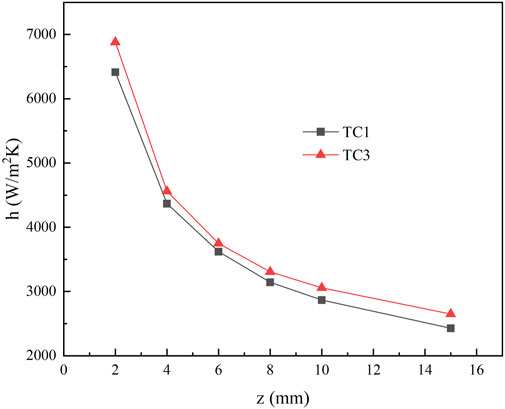
FIGURE 6. The local convective heat transfer coefficient of TC1 and TC3 along the heat sink length at a heat flux of 18,750 W/m2.
This enhanced mixing, causes the fluid to come into closer contact with the heat sink surface, resulting in a more effective transfer of heat from the surface to the fluid. On the other hand, when an external magnetic field is applied to a ferrofluid flow, the magnetic nanoparticles within the fluid become magnetized and align themselves in the direction of the magnetic field. This alignment of the magnetic nanoparticles can induce a convective flow within the ferrofluid, which can enhance the heat transfer rate of the heat sink. In addition, the aligned magnetic nanoparticles can act as a thermal conductor, facilitating the transfer of heat away from the heat sink. Finally, in this section, the effect of MF-IJ on the improvement of the local convective heat transfer coefficient in the designed heat sink is investigated. The simulation results for cooling of the heat sink utilizing the case of TC4 compared to cooling of the heat sink utilizing the case of TC1 are presented in Figure 7. As can be seen, based on the results, the maximum improvement local convective heat transfer coefficient for the designed heat sink increased by approximately 32% under the influence of MF-IJ compared to the pure water state (TC1). Therefore, the simultaneous use of ferrofluid flows inside the microchannels under the effect of magnetic field and the air impingement jet flow on the plate-fins of the heat sink, increases the heat transfer rate.
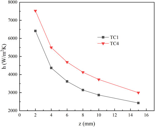
FIGURE 7. The local convective heat transfer coefficient of TC1 and TC4 along the heat sink length at a heat flux of 18,750 W/m2.
The effect of magnetic field intensity has been investigated on the improvement of the average heat transfer coefficient at an inlet mass flow rate of 0.005 kg/s, heat flux of 18,750 W/m2, and φ = 3% in Figure 8. Based on Figure 8, the average heat transfer coefficient increases with increasing magnetic field intensity. For example, at a Reynolds number of 600, by applying magnetic field intensities B = 400, 800, and 1600 G, the average heat transfer coefficient increases by 5.35, 11.77, and 16.11%, respectively. Furthermore, it is observed that the effect of the magnetic field on heat transfer was more pronounced at lower Reynolds numbers, suggesting that the magnetic field may be particularly effective in low fluid velocity applications. This observation is consistent with previous studies (Ashjaee et al., 2015) and may be because the magnetic field disrupts the thermal boundary layer and enhances the mixing of the fluid, leading to more effective heat transfer.
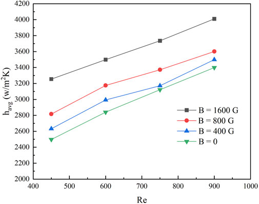
FIGURE 8. Effect of magnetic field utilizing impingement jet on the average heat transfer coefficient of ferrofluid at a heat flux of 18,750 W/m2,
The ferrofluid flow under the influence of the magnetic field increases the mixing of the fluid as well as, increasing the fluid’s thermal conductivity and decreasing the thermal boundary layer thickness. On the other hand, according to the results of Figures 9, 10, the air impingement jet flow induces turbulence and mixing in the boundary layer, and promotes the vortex shedding, by increasing the fluid velocity near the heat sink surface, which can reduce the wall temperature of the heat sink. For example, in the location of z = 0.02 m, by applying the impingement jet with the mass flow rates of 0.001, 0.004, and 0.005 kg/s, the wall temperature increases by 0.36, 1.62%, and 1.82%, respectively. Therefore, the combination of these two effects leads to a significant enhancement in heat transfer performance, as demonstrated by the observed increase in the local convective heat transfer coefficient.
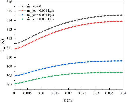
FIGURE 9. Wall temperature variation of the heat sink at B = 1,600 G, φ = 3%, Re = 900, and heat flux of 66,000 W/m2 for different inlet mass flow.
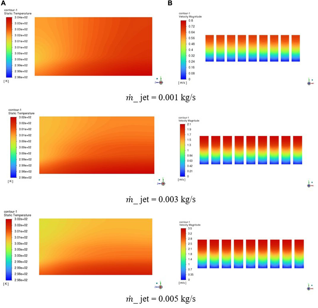
FIGURE 10. Study on the effect of increasing the inlet mass flow rate of impingement jet on the velocity of the jet and wall temperature of the heat sink at B = 1,600 G, Re = 900, φ = 3% and heat flux of 18750W/m2 (A) Temperature contour of the heat sink wall (B) Velocity contour at the middle channel of the heat sink.
The effect of the value of inlet mass flow rate of the impingement jet along the channel at a heat flux of 66,000 W/m2, Reynolds number of 900, B = 1,600 G, and φ = 3% is shown in Figure 9. It can be observed that the wall temperature of the heat sink at different cases has a similar trend, which decreased gradually as the inlet mass flow rate increased. The reason for this reduction is due to the increase in the convective heat transfer coefficient associated with the air flow. As the inlet mass flow rate is increased, the velocity of the air flow over the heat sink surface also increases, which creates more air motion inside the plate fins of the heat sink. Figure 11 shows the temperature contour of the longitudinal section of the microchannel heat sink at a heat flux of 18,750 W/m2, B = 1600 G, φ = 3%,
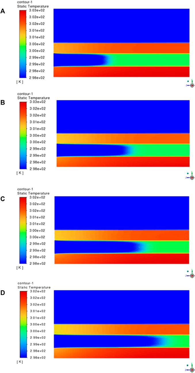
FIGURE 11. Temperature contour of the longitudinal section of the microchannel heat sink at heat flux of 18,750 W/m2, B = 1,600 G, φ = 3%,
Figure 12 shows the results of two cases of TC5 and TC6 on the wall temperature of the designed heat sink at a heat flux of 66,000 W/m2. As can be seen, in Figure 12A, where the cooling is only with pure water passing through the microchannels, the maximum temperature of the heat sink wall has reached 321 K, while for Figure 12B, where the cooling is done using a combination method of MF-IJ, the maximum temperature of the heat sink wall has been reduced to 308 K. Also, in Figure 12B, due to the presence of an impingement jet and magnetic field, the cooling of the upper and middle parts of the heat sink is done better than in Figure 12A, where there is no magnetic field and impingement jet. Therefore, using the proposed combination method of MF-IJ is more effective at high heat fluxes.
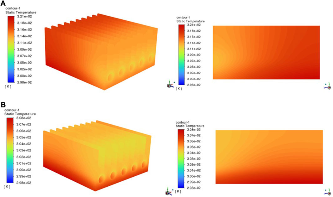
FIGURE 12. Wall temperature contour of the heat sink wall subject to a heat flux of 66,000 W/m2: (A) TC5 (B) TC6.
The effect of increasing the inlet mass flow rate of the impingement jet on the velocity of the impingement jet is shown in Figure 10B. Also, the effect of increasing the inlet mass flow rate of the impingement jet on the wall temperature of the heat sink is shown in Figure 10A. As can be seen, in Figure 10B, with the increase of inlet mass flow of the impingement jet, the maximum velocity inside the channels of the plate-fins increases. Therefore, according to Figure 10A, the wall temperature of the heat sink decreases. Moreover, according to Figure 10A, it can be seen that with moving from the top to the bottom of the heat sink, due to approaching the stagnation point, the velocity of the impingement jet gradually decreases.
Based on the findings presented in Figure 13, it can be observed that the velocity contours at the middle channel of the heat sink are affected by the variation of Reynolds numbers. By comparing Figures 11, 13, it is revealed that as the Reynolds number increases, the flow separation is delayed, and the velocity in the center of the microchannels of ferrofluid increases. Therefore, it is recommended that for the designed heat sink, increasing the Reynolds number can enhance heat transfer and lead to a decrease in the temperature of the heat sink wall. For example, the maximum wall temperature of the heat sink for a Reynolds number of 900 is approximately 301 K. These results highlight the importance of considering the Reynolds number as a key parameter for optimizing the design of microchannel heat sinks for efficient thermal management.
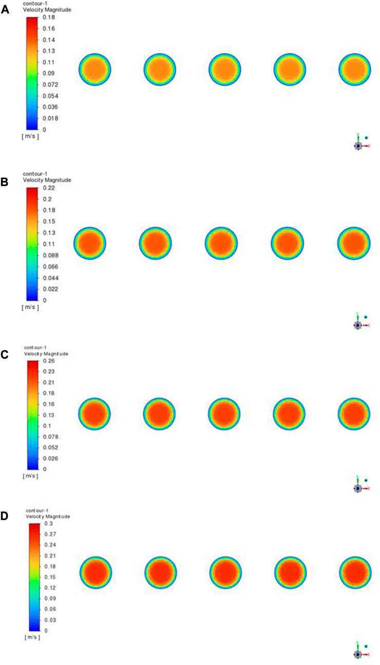
FIGURE 13. Velocity contour at the middle channel of the heat sink at a heat flux of 18,750 W/m2, B = 1,600 G and φ = 3% for ferrofluid flow: (A) Re = 450; (B) Re = 600; (C) Re = 750; (D) Re = 900.
7 Conclusion
In this study, the simultaneous effect of the impingement jet and an external magnetic field with magnetite ferrofluid flowing are numerically investigated on the improvements of the convective heat transfer coefficient of the proposed heat sink using a steady three-dimensional CFD approach. In this study, the impingement jet and the magnetic ferrofluid flows are considered to be turbulent and laminar, respectively. Finally, the following results are obtained:
• The cooling utilizing TC2 versus the heat sink cooling utilizing TC1 has the maximum improvement of convective heat transfer coefficient of 22.4%, and this amount of heat sink cooling using TC3 resulted in a 10% improvement.
• The use of the combination cooling method of MF-IJ could increase the maximum improvement of the convective heat transfer coefficient for this designed heat sink by 32% compared to the TC1.
• The average heat transfer coefficient of ferrofluid increases with increasing magnetic field intensity when subjected to the combination cooling method of MF-IJ. For example, at Re = 600, by applying magnetic fields B = 400 G, B = 800 G, and B = 1,600 G, the average heat transfer coefficient increases by 5.35, 11.77, and 16.11%, respectively.
• Increasing the Reynolds number of the ferrofluid and inlet mass flow of the impingement jet improved the cooling of the heat sink. At z = 0.02 m, the use of an impingement jet at different mass flow rates (0.001, 0.004, and 0.005 kg/s) causes a corresponding decrease in wall temperature (0.36%, 1.62%, and 1.82%, respectively).
• Using the proposed combination method (MF-IJ) for two heat flux values of 18,750 and 66,000 W/m2 in this study, it was concluded that MF-IJ can also be utilized for heat sinks with high heat flux generation.
This study investigated the effects of the combination of an external magnetic field and an impingement jet (MF-IJ) on the heat transfer process in a designed heat sink. It can be concluded that this combination has a significant effect on the cooling of the heat sink, leading to enhanced heat transfer performance. Implementation of advanced cooling techniques, such as the MF-IJ, can help reduce the use of harmful refrigerants that contribute to ozone depletion and global warming, promoting the use of more environmentally friendly cooling solutions. This discovery could have significant practical implications for a wide range of electronic cooling devices. By incorporating this new understanding into the design of heat transfer devices, engineers could potentially create more efficient and effective cooling systems, which in turn could have a greater effect on the cooling of heat sinks.
As a suggestion for future works, the following improvements can be considered:
⁃ Using porous fins instead of solid fins.
⁃ Using pin fin instead of plate fin.
⁃ Using a non-uniform jet instead of a uniform jet.
⁃ Using a non-uniform magnetic field instead of a uniform magnetic field.
Data availability statement
The original contributions presented in the study are included in the article/Supplementary Material, further inquiries can be directed to the corresponding author.
Author contributions
SA: Methodology, Data curation, Writing–original draft. AA: Supervision, and project administration, Writing–review and editing. AV: writing–original draft. HAh: Data curation, Supervision. HAf: Formal Analysis, Writing–original draft.
Funding
The author(s) declare that no financial support was received for the research, authorship, and/or publication of this article.
Acknowledgments
I hereby express my sincere acknowledgment to Islamic Azad University-South Tehran Branch-Tehran-Iran for its unwavering support and invaluable assistance throughout the entire duration of my research Ph.D. project.
Conflict of interest
The authors declare that the research was conducted in the absence of any commercial or financial relationships that could be construed as a potential conflict of interest.
Publisher’s note
All claims expressed in this article are solely those of the authors and do not necessarily represent those of their affiliated organizations, or those of the publisher, the editors and the reviewers. Any product that may be evaluated in this article, or claim that may be made by its manufacturer, is not guaranteed or endorsed by the publisher.
References
Abdolahipour, S., Mani, M., and Shams Taleghani, A. (2022b). Experimental investigation of flow control on a high-lift wing using modulated pulse jet vortex generator. J. Aerosp. Eng. 35 (Issue 5), 2022. doi:10.1061/(ASCE)AS.1943-5525.0001463
Abdolahipour, S., Mani, M., and Shams Taleghani, A. (2021). Parametric study of a frequency-modulated pulse jet by measurements of flow characteristics. Phys. Scr. 96 (No. 12), 125012. doi:10.1088/1402-4896/ac2bdf
Abdolahipour, S., Mani, M., and Shams Taleghani, A. (2022a). Pressure improvement on a supercritical high-lift wing using simple and modulated pulse jet vortex generator. Flow. Turbul. Combust. 109, 65–100. doi:10.1007/s10494-022-00327-9
Ashjaee, M., Goharkhah, M., Khadem, L. A., and Ahmadi, R. (2015). Effect of magnetic field on the forced convection heat transfer and pressure drop of a magnetic nanofluid in a miniature heat sink. Heat Mass Transf. 51, 953–964. . doi:10.1007/s00231-014-1467-1
Bahiraei, M., and Hangi, M. (2016). Automatic cooling by means of thermomagnetic phenomenon of magnetic nanofluid in a toroidal loop. Appl. Therm. Eng., 107, 700–708.doi:10.1016/j.applthermaleng.2016.07.021
Bahiraei, M., and Hangi, M. (2013). Investigating the efficacy of magnetic nanofluid as a coolant in double-pipe heat exchanger in the presence of magnetic field. Energy Convers. Manag. 76, 1125–1133. . doi:10.1016/j.enconman.2013.09.008
Bailey, R. L. (1983). Lesser known applications of ferrofluids. J. magnetism magnetic Mater. 39 (1-2), 178–182. . doi:10.1016/0304-8853(83)90428-6
Bar-Cohen, A. (1993). Thermal management of electronic components with dielectric liquids. JSME Int. J. Ser. B Fluids Therm. Eng. 36 (1), 1–25. . doi:10.1299/jsmeb.36.1
Bezaatpour, M., and Goharkhah, M. (2019). Effect of magnetic field on the hydrodynamic and heat transfer of magnetite ferrofluid flow in a porous fin heat sink. J. Magnetism Magnetic Mater. 476, 506–515. . doi:10.1016/j.jmmm.2019.01.028
Biber, C. R. (1997). Pressure drop and heat transfer in an isothermal channel with impinging flow. IEEE Trans. Components, Packag. Manuf. Technol. Part A 20 (4), 458–462. . doi:10.1109/95.650935
Byon, C. (2015). Heat transfer characteristics of aluminum foam heat sinks subject to an impinging jet under fixed pumping power. Int. J. Heat Mass Transf. 84, 1056–1060. . doi:10.1016/j.ijheatmasstransfer.2015.01.025
El-Shorbagy, M. A., Algehyne, E. A., Ibrahim, M., Ali, V., and Kalbasi, R. (2021). Effect of fin thickness on mixed convection of hybrid nanofluid exposed to magnetic field-Enhancement of heat sink efficiency. Case Stud. Therm. Eng., 26, 101037. doi:10.1016/j.csite.2021.101037
Forghan, F., Goldthwaite, D., Ulinski, M., and Metghalchi, H.(2001). “Experimental and theoretical investigation of thermal performance of heat sinks,” in Annual meeting for ISME (United States: ).
Fox, R. W., McDonald, A. T., and Mitchell, J. W. (2020). Fox and McDonald's introduction to fluid mechanics. Hoboken, New Jersey: John Wiley & Sons.
Froissart, M., Ziółkowski, P., Dudda, W., and Badur, J. (2021). Heat exchange enhancement of jet impingement cooling with the novel humped-cone heat sink. Case Stud. Therm. Eng. 28, 101445. . doi:10.1016/j.csite.2021.101445
Gan, T., Ming, T., Fang, W., Liu, Y., Miao, L., Ren, K., et al. (2020). Heat transfer enhancement of a microchannel heat sink with the combination of impinging jets, dimples, and side outlets. J. Therm. Analysis Calorim. 141, 45–56. . doi:10.1007/s10973-019-08754-z
Ganguly, R., Sen, S., and Puri, I. K. (2004). Thermomagnetic convection in a square enclosure using a line dipole. Phys. Fluids 16 (7), 2228–2236. . doi:10.1063/1.1736691
Hussain, A. A., Freegah, B., Khalaf, B. S., and Towsyfyan, H. (2019). Numerical investigation of heat transfer enhancement in plate-fin heat sinks: effect of flow direction and fillet profile. Case Stud. Therm. Eng. 13, 100388. . doi:10.1016/j.csite.2018.100388
Jalili, B., Rezaeian, A., Jalili, P., Ommi, F., and Ganji, D. D. (2023d). Numerical modeling of magnetic field impact on the thermal behavior of a microchannel heat sink. Case Stud. Therm. Eng. 45, 102944. . doi:10.1016/j.csite.2023.102944
Jalili, B., Roshani, H., Jalili, P., Jalili, M., Pasha, P., and Ganji, D. D. (2023b). The magnetohydrodynamic flow of viscous fluid and heat transfer examination between permeable disks by AGM and FEM. Case Stud. Therm. Eng. 45, 102961. doi:10.1016/j.csite.2023.102961
Jalili, P., Azar, A. A., Jalili, B., and Ganji, D. D. (2023a). Study of nonlinear radiative heat transfer with magnetic field for non-Newtonian Casson fluid flow in a porous medium. Results Phys. 48, 106371. doi:10.1016/j.rinp.2023.106371
Jalili, P., Narimisa, H., Jalili, B., and Ganji, D. D. (2023c). Micro-polar nanofluid in the presence of thermophoresis, hall currents, and Brownian motion in a rotating system. Mod. Phys. Lett. B 37 (01), 2250197. doi:10.1142/s0217984922501974
Jang, S. P., Kim, S. J., and Paik, K. W. (2003). Experimental investigation of thermal characteristics for a microchannel heat sink subject to an impinging jet, using a micro-thermal sensor array. Sensors Actuators A Phys. 105 (2), 211–224. . doi:10.1016/s0924-4247(03)00103-1
Jazmi, Ramin, Mohammadzadeh, Kazem, Hassan, Khaleghi, and Maddahian, Reza (2021). Numerical investigation of water droplet behavior in anode channel of a PEM fuel cell with partial blockage. Archive Appl. Mech. 91 (4), 1391–1406. doi:10.1007/s00419-020-01828-7
Johnson, M. J., and Go, D. B. (2016). Impingement cooling using the ionic wind generated by a low-voltage piezoelectric transformer. Front. Mech. Eng. 2, 7. doi:10.3389/fmech.2016.00007
Karimi, A., Goharkhah, M., Ashjaee, M., and Shafii, M. B. (2015). Thermal conductivity of $$\mathrm{Fe}_{2}\mathrm{O}_{3}$$ Fe 2 O 3 and $$\mathrm{Fe}_{3}\mathrm{O}_{4}$$ Fe 3 O 4 magnetic nanofluids under the influence of magnetic field. Int. J. Thermophys. 36, 2720–2739. . doi:10.1007/s10765-015-1977-1
Kim, D. K., Kim, S. J., and Bae, J. K. (2009). Comparison of thermal performances of plate-fin and pin-fin heat sinks subject to an impinging flow. Int. J. Heat Mass Transf. 52 (15-16), 3510–3517. . doi:10.1016/j.ijheatmasstransfer.2009.02.041
Kondo, Y., Behnia, M., Nakayama, W., and Matsushima, H. (1998). Optimization of finned heat sinks for impingement cooling of electronic packages, 259–266.
Koo, J., and Kleinstreuer, C. (2004). A new thermal conductivity model for nanofluids. J. Nanoparticle Res. 6, 577–588. . doi:10.1007/s11051-004-3170-5
Kotb, A., Askar, H., and Saad, H. (2023). On the impingement of heat transfer using swirled air jets. Front. Mech. Eng. 9, 1120985. doi:10.3389/fmech.2023.1120985
Li, H. Y., Chen, K. Y., and Chiang, M. H. (2009). Thermal-fluid characteristics of plate-fin heat sinks cooled by impingement jet. Energy Convers. Manag. 50 (11), 2738–2746. . doi:10.1016/j.enconman.2009.06.030
Li, Q., and Xuan, Y. (2009). Experimental investigation on heat transfer characteristics of magnetic fluid flow around a fine wire under the influence of an external magnetic field. Exp. Therm. Fluid Sci. 33 (4), 591–596. . doi:10.1016/j.expthermflusci.2008.12.003
Mirzaei, M., and TaleghaniShadaram, A. S. A. (2012). Experimental study of vortex shedding control using plasma actuator. Appl. Mech. Mater. 186, 75–86. doi:10.4028/www.scientific.net/amm.186.75
Mohammadi, M., and Taleghani, A. S. (2014). Active flow control by dielectric barrier discharge to increase stall angle of a NACA0012 airfoil. Arab. J. Sci. Eng. 39, 2363–2370. doi:10.1007/s13369-013-0772-1
Mohammadzadeh, K., Khaleghi, H., Khadem Abolfazli, H. R., and Seddiq, M. (2018). Effects of gas cross-over through the membrane on water management in the cathode and anode sides of PEM fuel cell. J. Appl. Fluid Mech. 11 (4), 861–875. doi:10.29252/jafm.11.04.28559
Naphon, P., Wiriyasart, S., Arisariyawong, T., and Nakharintr, L. (2019). ANN, numerical and experimental analysis on the jet impingement nanofluids flow and heat transfer characteristics in the micro-channel heat sink. Int. J. Heat Mass Transf. 131, 329–340. . doi:10.1016/j.ijheatmasstransfer.2018.11.073
Noori, S. M. S., Taeibi Rahni, M., and Shams Taleghani, S. A. (2020). Numerical analysis of droplet motion over a flat plate due to surface acoustic waves. Microgravity Sci. Technol. 32 (4), 647–660. doi:10.1007/s12217-020-09784-1
Pandey, J., Husain, A., Ansari, M. Z., and Al-Azri, N. (2022). Comparison of the parallel microchannel and Pin-Fin heat Sinks: an experimental study. Mater. Today Proc. 56, 845–850. doi:10.1016/j.matpr.2022.02.503
Pereira, P. R., Varga, S., Oliveira, A. C., and Soares, J. (2015). Development and performance of an advanced ejector cooling system for a sustainable built environment. Front. Mech. Eng. 1, 7. doi:10.3389/fmech.2015.00007
Sadighi, S., Afshar, H., Jabbari, M., and Ahmadi Danesh Ashtiani, H. (2022b). An analytical approach to entropy production in MHD mixed convection micropolar fluid flow over an inclined porous stretching sheet. Front. Mech. Eng. 8, 900316. doi:10.3389/fmech.2022.900316
Sadighi, S., Afshar, H., Jabbari, M., and Ashtiani, H. A. D. (2023). Heat and mass transfer for MHD nanofluid flow on a porous stretching sheet with prescribed boundary conditions. Case Stud. Therm. Eng. 49, 103345. doi:10.1016/j.csite.2023.103345
Sadighi, S., Jabbari, M., Afshar, H., and Ashtiani, H. A. D. (2022a). MHD heat and mass transfer nanofluid flow on a porous cylinder with chemical reaction and viscous dissipation effects: benchmark solutions. Case Stud. Therm. Eng. 40, 102443. doi:10.1016/j.csite.2022.102443
Salmasi, A., Shadaram, A., and Shams Taleghani, A. (2013). Effect of plasma actuator placement on the airfoil efficiency at poststall angles of attack. IEEE Trans. Plasma Sci. 41 (10), 3079–3085. doi:10.1109/tps.2013.2280612
Selvakumar, P., and Suresh, S. (2012). Convective performance of CuO/water nanofluid in an electronic heat sink. Exp. Therm. Fluid Sci. 40, 57–63. doi:10.1016/j.expthermflusci.2012.01.033
Sheikholeslam Noori, M., Shams Taleghani, A., and Taeibi Rahni, M. (2020a). Phenomenological investigation of drop manipulation using surface acoustic waves. Microgravity Sci. Technol. 32 (6), 1147–1158. doi:10.1007/s12217-020-09839-3
Sheikholeslam Noori, M., Shams Taleghani, A., and Taeibi Rahni, M. (2021). Surface acoustic waves as control actuator for drop removal from solid surface. Fluid Dyn. Res. 53 (4), 045503. doi:10.1088/1873-7005/ac12af
Sheikholeslam Noori, M., Taeibi Rahni, M., and Shams Taleghani, A. (2020b). Effects of contact angle hysteresis on drop manipulation using surface acoustic waves. Theor. Comput. Fluid Dyn. 34 (1), 145–162. doi:10.1007/s00162-020-00516-0
Singh, R., Ahmed, R., Karami, H., Nasser, M., and Hussein, I. (2021). CFD analysis of turbulent flow of power-law fluid in a partially blocked eccentric annulus. Energies, 14(3), 731.doi:10.3390/en14030731
Spalding, D. B. (1974). The numerical computation of turbulent flow. Comp. Methods Appl. Mech. Eng., 3, 269.
Taeibi Rahni, M., Shams Taleghani, A., Sheikholeslam, M., and Ahmadi, G. (2022). Computational simulation of water removal from a flat plate, using surface acoustic waves. Wave Motion 111, 102867, 102867. doi:10.1016/j.wavemoti.2021.102867
Taleghani, A. S., Shadaram, A., Mirzaei, M., and Abdolahipour, S. (2018). Parametric study of a plasma actuator at unsteady actuation by measurements of the induced flow velocity for flow control. J. Braz. Soc. Mech. Sci. Eng. 40 (No. 4), 173–213. doi:10.1007/s40430-018-1120-x
Taleghani, A. S., Shadaram, A., and Mirzaei, M. (2012). Effects of duty cycles of the plasma actuators on improvement of pressure distribution above a NLF0414 airfoil. IEEE Trans. Plasma Sci. 40 (5), 1434–1440. doi:10.1109/tps.2012.2187683
Wong, K. C., and Indran, S. (2013). Impingement heat transfer of a plate fin heat sink with fillet profile. Int. J. Heat Mass Transf. 65, 1–9. . doi:10.1016/j.ijheatmasstransfer.2013.05.059
Xie, Y., Jiang, C., Zheng, P., Cao, Z., and Luo, M. (2021). Ferrohydrodynamic and magnetohydrodynamic effects on jet flow and heat transfer of Fe3O4-H2O nanofluid in a microchannel subjected to permanent magnets. Symmetry 13 (11), 2051. . doi:10.3390/sym13112051
Xuan, Y., and Roetzel, W. (2000). Conceptions for heat transfer correlation of nanofluids. Int. J. heat Mass Transf. 43 (19), 3701–3707. . doi:10.1016/s0017-9310(99)00369-5
Zamzamian, A., Oskouie, S. N., Doosthoseini, A., Joneidi, A., and Pazouki, M. (2011). Experimental investigation of forced convective heat transfer coefficient in nanofluids of Al2O3/EG and CuO/EG in a double pipe and plate heat exchangers under turbulent flow. Exp. Therm. Fluid Sci. 35 (3), 495–502. . doi:10.1016/j.expthermflusci.2010.11.013
Zhong, J. F., Sedeh, S. N., Lv, Y. P., Arzani, B., and Toghraie, D. (2021). Investigation of Ferro-nanofluid flow within a porous ribbed microchannel heat sink using single-phase and two-phase approaches in the presence of constant magnetic field. Powder Technol. 387, 251–260. doi:10.1016/j.powtec.2021.04.03
Sadighi, S., Afshar, H., Ashtiani, H. A. D., and Jabbari, M. (2023). MHD flow and conductive heat transfer on a permeable stretching cylinder: benchmark solutions. Case Stud. Therm. Eng. 44, 102886. doi:10.1016/j.csite.2023.102886
Nomenclature
Appendix A
Keywords: flow control, impingement jet, magnetic field, heat sink, ferrofluid, enhancement of heat transfer
Citation: Azadi S, Abjadi A, Vahdat Azad A, Ahmadi Danesh Ashtiani H and Afshar H (2023) Enhancement of heat transfer in heat sink under the effect of a magnetic field and an impingement jet. Front. Mech. Eng 9:1266729. doi: 10.3389/fmech.2023.1266729
Received: 25 July 2023; Accepted: 16 August 2023;
Published: 30 August 2023.
Edited by:
Arash Shams Taleghani, Aerospace Research Institute, IranReviewed by:
Ebrahim Afshari, University of Isfahan, IranD. D. Ganji, Babol Noshirvani University of Technology, Iran
Alireza Dehghanisanij, University of Waterloo, Canada
Copyright © 2023 Azadi, Abjadi, Vahdat Azad, Ahmadi Danesh Ashtiani and Afshar. This is an open-access article distributed under the terms of the Creative Commons Attribution License (CC BY). The use, distribution or reproduction in other forums is permitted, provided the original author(s) and the copyright owner(s) are credited and that the original publication in this journal is cited, in accordance with accepted academic practice. No use, distribution or reproduction is permitted which does not comply with these terms.
*Correspondence: Ali Abjadi, YV9hYmphZGlAYXphZC5hYy5pcg==