 G. Nasif
 A.-M. Shinneeb
 R. Balachandar
- 1Department of Mechanical, Automotive, and Materials Engineering, Windsor, ON, Canada
- 2Department of Civil and Environmental Engineering, University of Windsor, Windsor, ON, Canada
A computational study has been performed to evaluate the use of jet impingement for cooling applications in the automotive industry. The current study uses an entire internal combustion engine cylinder with its components as a computational domain. An unsteady numerical solution for the Navier-Stokes equations was carried out using Improved Delayed Detached Eddy Simulation (IDDES). The volume of fluid approach is proposed to track and locate the liquid jet surface that is in contact with the air. The conjugate heat transfer approach is used to link the heat transfer solution between the fluid and the solid. The boundary conditions that are employed in the study are provided from lab experiments and one-dimensional simulations. The cooling jet in this study targets the hottest region in the piston, i.e., the region underneath the exhaust valve. Three nozzle sizes with flows at different Reynolds numbers are chosen to examine the thermal characteristics of the cooling jet. The computational study reveals that for a specific Reynolds number, the smaller diameter nozzle provides the highest heat transfer coefficient around the impingement point. The maximum relative velocity location at the impingement point slightly leads the location of the maximum Nusselt number. The maximum temperature in the piston decreases by 7% to 11% as the nozzle diameter changes from 1.0 to 3.0 mm for a jet Reynolds number of 4,500. If a correct selection is made for the nozzle size, the cooling jet can be efficiently used to reduce the temperature and alleviate the thermal stresses in the piston in the region underneath the exhaust valve where the maximum temperature occurs.
1 Introduction
Impinging cooling jets are well recognized to provide large heat transfer coefficients and are hence widely employed in numerous engineering and industrial applications. Impinging jets have been used to transfer heat for various purposes, including but not limited to the drying of paper and the cooling of electronic boards. In the automotive industry, the pistons convey the power produced by the burning mixture to the crankshaft via the connecting rod, and together with their rings, they confine the combustion space from the other parts of the engine (crankcase). For obvious reasons, the temperature of the combustion chamber is expected to be the highest in the engine. Since the piston occupies the bottom portion of the combustion space, it is the only part that is not cooled by the engine cooling system. A large amount of the heat is dissipated from the piston via the sealing rings to the combustion chamber’s inner walls. The heat transfer also occurs through the wrist pins of the piston and the connecting rods. There is a need for improving engine performance while decreasing the available space in the engine compartment. At high engine speeds and loads, the consequence of raising the engine power is that it affects the structural endurance of the piston alloy making it vulnerable to fatigue failure. In the last decade, manufacturers have considered the use of impinging jets in their vehicles to eliminate the overheating that may occur in the piston and to meet lower exhaust gas concentrations (Nasif, 2014).
When a free jet impinges a surface, the velocity field can be split into an exterior inviscid zone and an interior viscous zone which represents the boundary layer. A very thin stagnation region develops normally to the jet axis. This layer has small resistance to heat transfer, where the convective heat transfer coefficient is very high. After the impingement, the flow extends thinner in the radial direction, i.e., the thickness of the liquid layer near the wall reduces with radius. This decrease brings the developing boundary layer into contact with the surface of the fluid layer. At this point, the fluid layer thickness starts to increase at farther radii due to the viscosity effect, the drag due to the viscosity decelerates the flow and widens the liquid layer (Liu et al., 1991).
Both experimental (Cao et al., 2022; Wei and Zu, 2022; Barewar et al., 2023; Plant et al., 2023; Shaikh et al., 2023) and numerical (Nasif et al., 2016; Nasif et al., 2018a; Nasif et al., 2022a; Ewe et al., 2022; Cui et al., 2023) analyses have been performed to study the heat transfer attributes of impinging jets. However, there are many essential issues to be addressed, especially in cases where impingement heat transfer is accompanied by a moving boundary in a confined space. These features are crucial in providing better insight into engine performance and improving other industrial applications. J. John et al., (Mili et al., 2020), investigated the thermal and flow characteristics of a two-dimensional isothermal jet that impinges an inclined surface. The Reynolds-averaged Navier–Stokes (RANS) equations based on the standard k–ε turbulence model has been used to predict the flow fields. The angle of the surface inclination with respect to the impinging jet is varied between 0° and 10°, the jet Reynolds number in this investigation is fixed (Re = 11,500), and constant heat flux is employed as a boundary condition. The study revealed that the flow field remains symmetric about the jet centerline at 0°; however, with the increase of angle of inclination, the flow field becomes asymmetric. The location at which the jet impinges on the bottom wall gradually moves more toward the right side of the jet centerline with increasing the angle of inclination. The flow field significantly affects the heat transfer field, the Nusselt number decreases drastically as the angle of inclination is increased from 0° to 10°. Ashish et al., (Mishra et al., 2021), studied and analyzed the cooling process of electronic components using a sinusoidal synthetic jet. The study revealed that the synthetic jet is an effective method of removing hot spots in many engineering and industrial applications, i.e., processors and electronic chips. Other engineering applications of hybrid jet (combinations of synthetic and continuous jet) is also discussed in Singh et al. (2021).
The thermal characteristics of linear moving plates using water impinging jets are investigated experimentally Sharma and Kumar Sahu (2019). During tests, the initial temperature of the plate was maintained at approximately 500°C. Various jet Reynolds numbers, in the range of 2,500 and 10,000, were employed in the investigation. The speed of the plate altered between 0 and 40 mm/s during the experiment. The space between the nozzle and the plate was kept constant at
Alotaibi et al. (2020) summarized the most essential outcomes for jet impingement on a stationary and rotating disc. Several important investigations dealing with numerical and experimental studies are reviewed and presented in Alotaibi et al. (2020). Many parameters are identified to influence the flow and enhance mass and energy transfer such as; Reynolds number, nozzle configuration, nozzle-to-target spacing, angle of incidence of the impinging jet, and the flow regime and profile at the nozzle exit. In the case of a rotating disc, Alotaibi et al. (2020) explained that the centrifugal force has a significant impact on the vortex dynamics in different regions of the impinging jet. Several other studies on a rotating disc neglected the effect of the rotational motion on the velocity field. The disc rotation can improve the heat transfer coefficient as stated in Nasif (2014). This combination of jet velocity and disc angular velocity can be investigated using simultaneous velocity and heat transfer measurements. The heat transfer characteristics of a free impinging jet on a rotating disc subjected to heat flux were also investigated by Jiang et al. (2021) using the CFD approach. Numerical simulations were performed over a wide range of jet Reynolds numbers, issuing temperatures, nozzle sizes, and various nozzle-to-disc spacings. The results showed that the local Nusselt number increases first and then decreases along the radial direction from the disc center. The Nusselt number attains its peak in the core heat transfer zone close to the rotation center. The study also showed that as nozzle size increases, the Nusselt number increases, and the temperature distribution on the disc surface becomes more uniform.
Nasif et al. (2015) conducted a computational study to evaluate the thermal properties of a circular jet striking a finite-thickness circular moving disc. The piston motion equation is used to impart the reciprocating motion to the disk. Different values of uniform heat flux are used as boundary conditions in this investigation. A volume of fluid (VoF) technique is employed to track and locate the interface between liquid and air. In the study, a procedure was introduced to expedite the simulation and cut down the CPU time by taking advantage of the recurring transient Nusselt number profile. This occurs when the temperature profile in the disc reaches the final steady distribution. The study also revealed that the heat transfer mechanism is more efficient in a moving disc compared to a fixed one. The highest coefficient of heat transfer (HTC) due to impinging jet occurs in a small region around the impingement point where the velocity gradient in the radial direction is greater than zero. Nasif et al. (2015) explained that this stagnation region exists in the accelerating flow adjacent to the stagnation point and develops up to the location where the positive velocity gradient switches to a negative one in the near-wall liquid film. The stagnation point refers to a location on the disc where the jet velocity is brought to zero, i.e., the location where the jet kinetic energy converts to potential energy.
The effect of conjugate heat transfer (CHT) was numerically investigated by Nasif et al. (2018b) using air and water as working fluids. The study reveals that for the air jet, the Nusselt number value at the stagnation region always decreases as the boundary heat flux increases for the process that involves conjugate heat transfer. The disc thickness and disc metal influence the stagnation Nusselt number profile. Nasif et al. (2018b) also stated that the effect of the conjugate heat transfer and thermal heat flux on the Nusselt number at the stagnation point is very minor for the water jet. The material and thickness of the disc did not affect the profile with the water jet. The computational results illustrate that the heat flux at the stagnation region due to convection for the water jet is less than that for the air jet for a specific operating condition, i.e., the same nozzle size and jet Reynolds number. The study also revealed that the conductive heat transfer within the solid acts to rearrange the heat flux at the interface. Consequently, a uniform temperature boundary is generated at the interface of the fluid and the solid for both working fluids (air or water) with high thermal conductivity metals.
The final goal of the current study is to use the computational fluid dynamics approach (CFD) to examine the use of the jet cooling technique on piston cooling. The effect of the nozzle size is examined using three nozzle sizes. The issuing bulk velocity from each nozzle is adjusted to provide a constant jet Reynolds number of Red = 4,500. The effect of the jet Reynolds number on the thermal characteristics is also investigated. Engine oil is employed as a working fluid and used as a cooling jet. A piston motion formula is employed to convey a reciprocating motion of the piston as a function of crankangle in the range of its movement. An angular velocity of 210 rad/s (2000 rpm) was chosen in the study, which represents the normal engine speed on highways. The boundary conditions that are employed in the study are provided from lab experiments and one-dimensional simulations. The CHT technique is employed to link the heat conduction in the solid region with the convective process at the solid-fluid interface. The radiation heat transfer is neglected in this study.
2 Computational methodology
The process of the cooling enhancement in the current study is modelled using Simcenter Star-CCM+ code with a polyhedral mesh. The advantage of using polyhedral mesh is that they usually have several neighbours, so that properties gradients can be better evaluated using linear functions. The time-dependent governing equation comprises the conservation of energy, mass, and momentum equations. First-order implicit time marching is used to discretize the time, while second-order spatial differencing is used to discretize the space in these equations. Each of these equations can be stated in a common form by the transport of a particular scalar quantity
Here
The flow domain in the current study comprises two fluids, i.e., air and oil. Therefore, a model to manage two-phase flow is required for the simulation. The volume of fluid (VoF) introduced by Hirt and Nichols (Hirt and Nichols, 1981) is a simple and efficient technique that provides a method to locate and track the movement of the interface between the different phases. The transport equation for the volume fraction
One aspect of importance in the VoF approach is to discretize the convective term in Eq. 2 to prevent false diffusion due to numerical smearing. High-resolution schemes (Muzaferija, 1999; Ubbink and Issa, 1999; Wacławczyk and Koronowicz, 2008) are effective in resolving this problem. A High-Resolution Interface-Capturing scheme (Muzaferija, 1999) is employed for capturing the interface in this study. The scheme depends on the use of a normalized variable diagram (Leonard, 1991), which gives the procedure for constructing high-resolution schemes. In this scheme, the local Courant-Friedrichs-Lewy (CFL) requirement (Courant number ≤ 1.0) should be met to guarantee numerical stability (Spalart, 2001). Meeting the CFL criterion requires observing and adjusting the time step to perform a balance of spatial with temporal discretization. In the present study domain, many crankangles (time steps) were checked to meet the CFL condition. The final time step based on a crank angle of 0.5° for an engine rotational speed of 2000 rpm is chosen for the simulation. This facilitates the Courant number to be smaller than 0.5 in the whole domain. For each time step, twenty internal iterations were chosen in the current computational study.
Although large-eddy simulation (LES) is not as computationally expensive as direct numerical simulation (DNS), it is still too costly for most engineering and industrial applications. This cost is very large in attached turbulent boundary layers as the turbulence scales approach Kolmogorov length scales. To bridge the gap between Reynolds-averaged Navier-Stokes models (RANS) and LES, combined RANS-LES methods are frequently employed. One such method, which possibly exhibits the greatest potential for extensive practical and engineering applications, is detached eddy simulation (DES). In this approach, the RANS method trigger at places where the turbulent length scales are smaller than grid dimensions and required to be modelled, i.e., near the solid surfaces. The LES mode is triggered at places where the grid dimensions become less than the turbulent scales. Therefore, the grid size will be less strict than in a pure LES method.
In the current study, the
The earliest type of detached eddy simulation encountered several issues as explained by Spalart (2009). The delayed detached eddy simulation (DDES) (Travin et al., 2002; Menter and Kuntz, 2004; Spalart et al., 2006) and advanced delayed detached eddy simulation (IDDES) turbulence model (Shur et al., 2008) have consequently been proposed to moderate the shortcomings addressed by Spalart (2009). The
The segregated method (Versteeg and Malalasekera, 2007) is employed to solve the discretized equations. In the segregated method, each of the transport equations for the solution variables is solved one after another. Every equation, while being solved, is “decoupled” or “segregated” from other equations. The segregated method is memory-resourceful since the discretized equations need to be saved in the memory one at a time. The numerical results are considered to have converged when the average temperature of the piston does not significantly change with crankangle. Simulataneously, the scaled continuity and momentum residuals should drop below 10–6.
3 Problem description
Figure 1 illustrates the computational domain of the current study. Three different nozzles with internal diameters of d = 1.0, 2.0, and 3.0 mm are used in the study. The nozzle exit appears at the bottom part of the domain as shown in Figure 1B. The distance between the nozzle exit and the bottom surface of the piston is 50 mm when the piston is at its Bottom Dead Center (BDC) while it is 130 mm when the piston is at its Top Dead Center (TDC). In the first set of simulations, the jet exit velocity is adjusted to provide a constant Reynolds number of Red = 4,500 for all three nozzles to evaluate the role of the nozzle diameter on the thermal attributes. In the second set of simulations, other jet exit velocities are employed to provide different jet Reynolds number ranges of 1,000–10,000 to examine the influence of the jet Reynolds numbers on the thermal attributes. The fully developed velocity profiles are acquired from separate simulations using very long pipes with different diameters ranging from 1.0 to 3.0 mm. Engine oil at 90°C is used as a working fluid in all simulations in the current study. For all cases, the fully developed velocity profiles are mapped at the nozzle exit, which represents the inlet boundary to the domain. The oil exits the nozzle as a jet and upon impingement spreads as a wall jet along the piston’s inner surface as shown in Figure 1F. The jet path is following the nozzle exit and extends up to the inner surface of the piston, this path appears as a cylindrical part (oil-air interface) in Figures 1A, B, D, E. The jet path is morphed with the piston motion within the stroke. Therefore, the length of this path is a function of the crankangle. The boundary condition at the bottom of the present computational domain is obtained from the simulation of the entire crankcase of the engine, i.e., four cylinders with their pistons, crankshaft, etc., with no cooling jet. The flow field in the full-scale engine involves significant complexity in terms of multi-physics, tight geometry, moving parts, etc. Many thermal and fluid variables interact in this complicated process. Various meshing and mesh moving techniques are required, including arbitrary sliding interface (ASI) of counterweights and mesh morphing to replicate the linear motion of the piston. The boundary condition from the full-scale engine is recorded (temperature, pressure, and turbulence statistics) as a function of the angle of rotation of the crankshaft and mapped at the bottom of the current domain in the transient simulation. The location of the mapping of the recorded boundary condition is shown in Figures 1A, B. The crankcase in the current study is substituted with a small cylindrical part below the cylinder as shown in Figures 1A, B, D, E. The crankcase isn’t required to be modeled in the current study because the recorded boundary condition is brought from the crankcase and mapped at the bottom of the small cylindrical part in Figure 1. This will significantly reduce the computational effort.
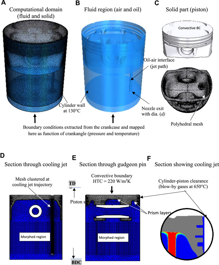
FIGURE 1. Computational domain of the current study with boundary conditions.
As a result of the presence of burning gasses within the combustion chamber, the top face of the piston is exposed to heat transfer due to convection. The temperature profile with corresponding average heat transfer coefficients over one cycle is acquired from a separate one-dimensional simulation. The temperature distribution of the combustion gases at the top surface of the piston is split into four concentric zones ranging from 550°C at the center to 1,100°C at the edges of the piston. The cylinder wall, which is enclosed by the coolant, is maintained at a fixed temperature over the cycle, i.e., T = 130°C. Fluid properties in the computational domain are calculated using the local temperature. The density (ρ), dynamic viscosity (µ), thermal conductivity (
The criteria for choosing the cell count in the current study are based on our previous study (Nasif, 2014). The piston motion formula, which creates a reciprocating movement of the piston, is employed in the simulation. The piston velocity is a function of connecting rod length, crank radius, and crankangle. The morphing method is needed to reproduce the piston movement within its stroke as shown in Figures 1D, E. A specific region in the computational domain will be subjected to morphing to create the reciprocating motion of the piston as shown in Figure 1. The mesh is packed at the jet path to prevent the false diffusion of the oil to the air due to the use of the VoF method. To better capture the air-oil interfaces and to accurately compute the HTC near the solid surfaces, ten prism layers are placed at a thickness of 0.4 mm from the surface using a stretching factor of 1.25, resulting in a y+ less than three. It was found from our previous study (Nasif, 2014) that HTC is very sensitive to the cell size near the wall. Therefore, the selection of the number and size of the prism layers was carefully conducted and based on a comparison of the numerical results for the HTC from the simulations with the experimental data (Nasif, 2014). The conjugate heat transfer (CHT) analysis accurately predicts heat transfer by simultaneously solving all the relevant solid and flow field heat transfer processes. The CHT analysis is used in the present study to evaluate the HTC at the solid-fluid interfaces. The convective HTC between the solid (piston) and the fluid (oil and air) is conveniently expressed as (Cengel et al., 2011):
The convective heat transfer coefficient in the above equation is assessed based on a reference temperature (
4 Validation
Validation entails the correct representation of the physics of flow (equations, turbulence models, etc.), appropriate numerical schemes (upwinding, time march, etc.), and model predictions (mesh issues, order of approximation, etc.). As such, the simulation results should be validated by comparison with experimental results or previous empirical correlations. If experimental results are not available, one can approximately assess the numerical results for a comparable problem for which data exists with relevant fundamental physics.
Presently, there are no available experimental results to validate a numerical study involving jet impingement onto a high-speed disc with finite thickness subjected to heat flux. Consequently, the computational results (i.e., local and stagnation Nu) were compared for the impinging jet on a static disc conducted in an earlier study (Nasif et al., 2014) for which experimental data are accessible (Stevens and Webb, 1991). The validation results presented in (Nasif et al., 2014) used three nozzle diameters and a broad range of jet Reynolds numbers. Empirical expressions to anticipate thermal attributes presented in (Stevens and Webb, 1991) were employed to validate the numerical results. The validation process showed variations of 3.5, 5.0, and 8.0% in the stagnation Nu for nozzle diameters of
5 Results and discussion
It is very important for heat transfer enhancement process to understand the flow field. Throughout this study, we have focused on the operating parameters that enhance piston cooling. The flow field of the jet impingement process, including VOF, has been extensively investigated in our previous papers (Nasif, 2014; Nasif et al., 2015; Nasif et al., 2016). In the current study, parallel computing was adopted to run the simulations and to reduce the computational time by utilizing the available resources of computing (32 cores). Four simulations were carried out with each nozzle size
The oil jet hits the impingement point; a portion of it splashes and the rest spreads at the bottom face of the piston. The relative velocity of impingement is denoted by
Here
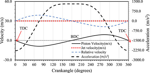
FIGURE 2. Variation of the reciprocating motion of the piston and the relative velocity for one cycle (N = 2000 rpm).
To understand the thermal properties of the jet-impinging process, the area surrounding the stagnation point is split into three zones. The thermal characteristics are averaged over each zone (surface averaged) and compared for the three nozzles and different Reynolds numbers. The first zone extends from r = 0.0 mm–0.9 mm, the second zone extends from r = 0.9 mm–1.8 mm, and the third zone extends from r = 1.8 mm–2.7 mm, here r represents the radial distance from the impingement point. The first zone region is selected based on the criterion that the maximum HTC occurs at the stagnation region (small viscous region) around the impingement point. This region extends approximately up to a radial distance of
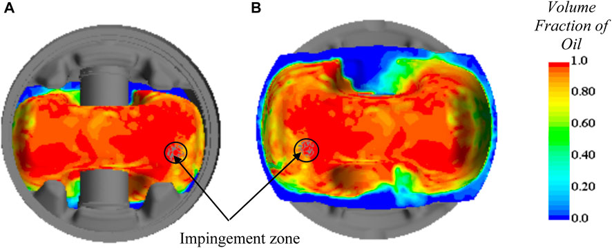
FIGURE 3. Volume of fluid (VoF) contour at the inner shell of the piston; (A) looking at the shell from a bird’s eye view after removing the upper part of the piston, (B) looking at the shell from the bottom.
Due to the reciprocating motion of the piston and the variable nozzle-to-target distance during the cycle, it is expected that the HTC will be a function of the crankangle and change periodically over the cycle. Figure 4 shows the transient Nusselt number
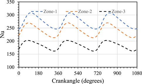
FIGURE 4. Surface average (averaged over pre-defined zones) transient Nu with cooling jet over three engine cycles at Red = 4,500 and nozzle diameter of d = 2.0 mm.
Figure 5 shows the temperature contours with and without the impinging jet, The jet Reynolds number Red = 4,500 is constant for all three nozzles. Figure 5A shows the temperature distribution for the entire piston, while Figure 5B shows the temperature distribution on the inner surface of the piston. The flow and thermal characteristics of the cooling jet averaged over one cycle for three nozzles using jet Reynolds number of Red = 4,500 are listed in Table 1. The effect of the diameter of the nozzle on the piston temperature profile is apparent in Figure 5. For a specific Re, the larger nozzle diameter provides a more uniform and consistent temperature distribution on the bottom face of the piston compared to the smaller nozzle as shown in Figure 5B. The lower temperature contour extends farther on the upper face of the piston as the nozzle diameter increases. The cooling jet lowers the maximum temperature at the inner and upper faces of the piston (beneath the exhaust valve) and shifts the location of its occurrence at the inner surface to the opposite side as shown in Figure 5B. It can be concluded from Figure 5 that the temperature averaged over the volume of the piston decreases by 9%, 12%, and 13% while the inner surface average temperature of decreases by 15%, 19%, and 21% corresponding to
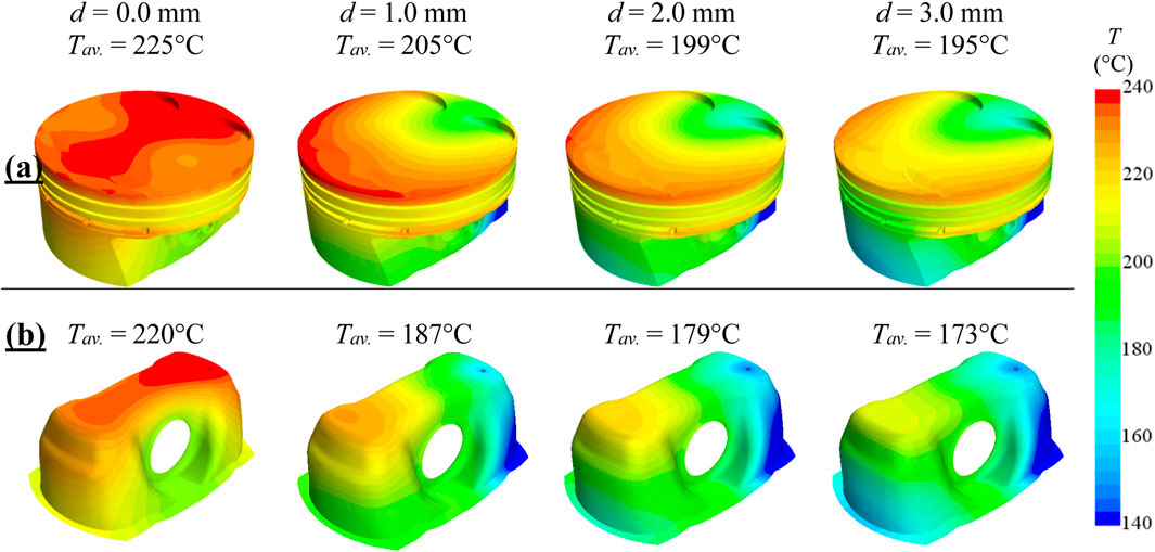
FIGURE 5. The effect of nozzle diameter on the temperature distribution using constant Reynolds number of Red = 4,500: (A) whole piston, (B) piston inner shell.
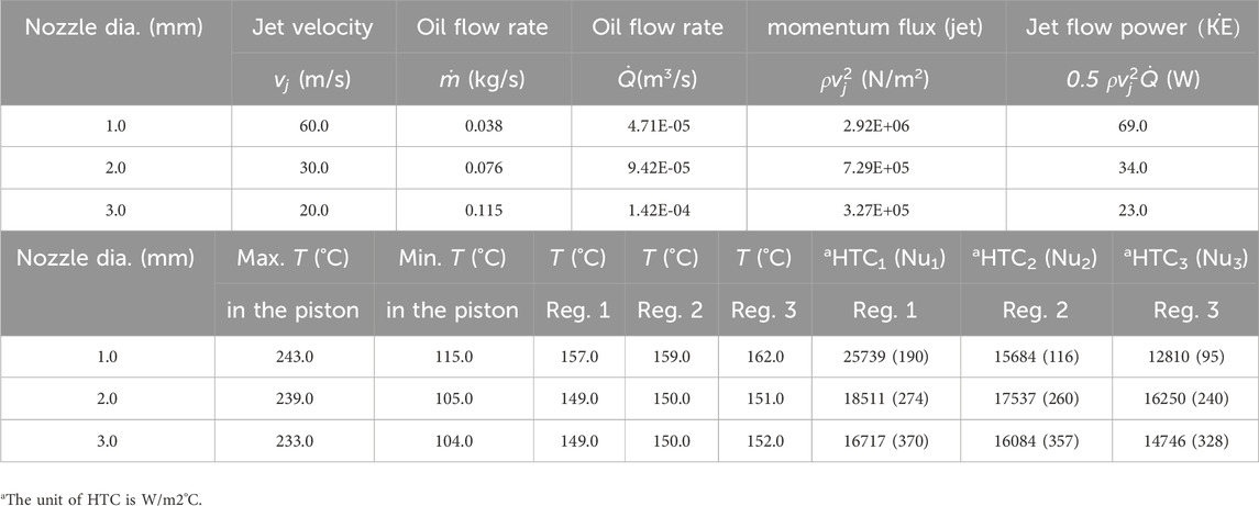
TABLE 1. Flow and thermal characteristics averaged over one cycle (360°) for the cooling jet at Red = 4,500.
Table 1 shows that for a specific Re, the greatest heat transfer coefficient (surface averaged over one cycle) in the first zone is achieved with a nozzle of a smaller diameter. This is because the high velocity of the jet creates the greatest radial velocity gradient with the smaller nozzle at the stagnation point. The HTC value drops by 35% for the larger nozzle compared to the smaller one in the first zone around the stagnation point. For a given nozzle size, the HTC starts to drop, as one moves away from the impinging point due to the decline in the radial velocity gradient. At larger radii from the impinging point, the radial velocity gradient declines as fluid film thickness begins to increase, while the boundary layer develops (Liu et al., 1991). Contrary to HTC, the Nu increases with the nozzle size as shown in Table 1. The Nu (averaged over the cycle) drops by 50%, 12%, and 11% of its original value from the first zone to the third zone, corresponding to
Most of the jet energy issuing from the nozzle is in the form of kinetic energy. As shown in Table 1 and for a given Reynolds number, the pumping power required for a smaller nozzle is approximately three times greater than the larger one, if potential energy and friction losses are neglected. On the other hand, more heat will be removed from the piston with the larger nozzle due to the associated higher volume flow rate as shown in Table 1. Therefore, a larger and more efficient heat exchanger is required for the larger nozzle (this is not the focus of the study) to cool down the engine oil. These factors should be taken into consideration upon using the jet for cooling applications.
To get an understanding of the influence of the jet Re on thermal characteristics in the first zone, both HTC and Nu are plotted versus the Reynolds number as shown in Figure 6. In this figure, the corresponding nozzle diameter is used to define the Nusselt number for each case, therefore the Nu in this figure is a function of both HTC and length scale (d). It is clearly shown in Figures 6A, B that the heat transfer coefficient and Nu at the impingement zone are more susceptible to Reynolds number with the smaller nozzle. However, as the size of the nozzle increases, the heat transfer coefficient and Nu do not change significantly with the Reynolds number. The profiles in Figures 6A, B appear more flat over a large range of Reynolds numbers for
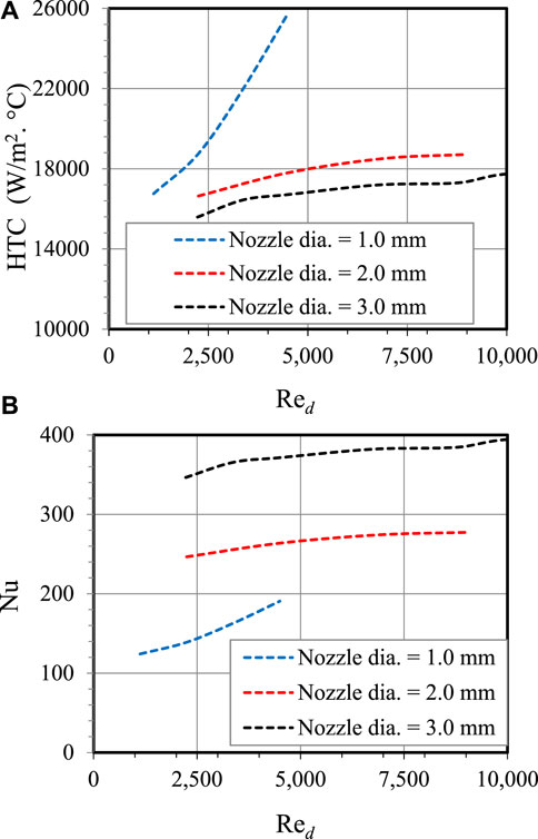
FIGURE 6. The effect of the jet Re on HTC and Nu for varying diameters in the first zone (0.0 mm ≤ r < 0.9 mm).
Figure 7 shows the effect of the jet Re on the average and the highest temperature experienced by the piston. A closer examination of Figure 7 reveals that the maximum drop in volume averaged temperature of the piston for any Reynolds number does not exceed 6°C between any two consecutive nozzle sizes. Furthermore, the difference is less between
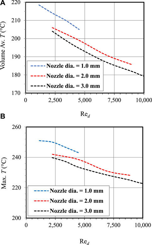
FIGURE 7. The effect of the jet Re on the average and maximum temperature experienced by the piston for varying nozzle diameters.
Figure 8 shows the effect of the jet Re on the average temperature in the first zone. Contrary to the HTC and Nu profiles that were discussed earlier, Figure 8 shows that the effect of the nozzle diameter is minor on the temperature distribution of the impingement region over a range of Reynolds numbers for
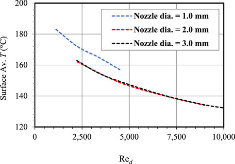
FIGURE 8. The effect of the jet Re on the average temperature in the first zone (0.0 ≤ r < 0.9) for varying nozzle diameter.
6 Conclusion
A computational study of an impinging jet onto a high-speed moving piston (N = 2000 rpm) was performed to identify the thermal characteristics. Engine oil jet at 90°C is used as a working fluid. Three nozzle diameters are employed in the study varying from 1.0 to 3.0 mm to investigate the role of diameter and jet Re. A mesh morphing technique is used in the simulations to change the position of the piston without affecting the underlying geometry of the computational domain. The conclusions of the current study can be summarized as follows:
I. Both HTC and Nu do not vary notably with the Reynolds number in the impingement region when the nozzle diameter is large. The HTC and Nu are largely independent of Re. Contrarily, both HTC and Nu are sensitive to changes in the Reynolds numbers when the nozzle diameter is small.
II. For a specific value of jet Reynolds number, the larger nozzle provides a more uniform and consistent temperature distribution on the bottom face of the piston compared to the smaller nozzle. The region of the lower temperatures on the top face of the piston increases more as the nozzle size becomes larger.
III. For a specific value of jet Reynolds number, the average and maximum temperatures of the piston are slightly dependent on the nozzle diameter.
IV. Although the HTC is greatest at the impingement region for the smaller nozzle, the temperature at this region is less for the larger size nozzle at any given Reynolds number.
V. The location of maximum relative velocity leads the location of the maximum Nusselt number that occurs at the impingement region. This may be attributed to the turning process of the cooling jet which adjusts the jet to be parallel to the bottom surface of the piston (wall jet). The turning process takes a few degrees of the crankangle during which the jet adjusts itself and the maximum radial velocity gradient takes place.
VI. The present study reveals that the impinging jet can substantially reduce the temperature (if a proper nozzle is chosen) of the region underneath the exhaust valve where the location of the maximum temperature occurs in the piston with no cooling jet.
VII. Based on the analysis presented herein, a nozzle diameter of 2.0 mm and a jet Re = 5,000 is more convenient and proper for piston cooling.
Data availability statement
The original contributions presented in the study are included in the article/Supplementary Material, further inquiries can be directed to the corresponding author.
Author contributions
GN: Conceptualization, Methodology, Validation, Formal analysis, Investigation, Data curation, Writing–original draft. RB: Conceptualization, Project administration, Funding acquisition, Writing–review and editing. A-MS: Conceptualization, Project administration, Writing–review and editing. All authors contributed to the article and approved the submitted version.
Acknowledgments
The assistance of the Natural Sciences and Engineering Research Council (NSERC) of Canada is appreciatively recognized. This research was made feasible by the facilities of the Shared Hierarchical Academic Computing Network and Compute/Calculator Canada.
Conflict of interest
The authors declare that the research was conducted in the absence of any commercial or financial relationships that could be construed as a potential conflict of interest.
Publisher’s note
All claims expressed in this article are solely those of the authors and do not necessarily represent those of their affiliated organizations, or those of the publisher, the editors and the reviewers. Any product that may be evaluated in this article, or claim that may be made by its manufacturer, is not guaranteed or endorsed by the publisher.
References
Alotaibi, H. M., El Hassan, M., Assoum, H. H., Meraim, K. A., and Sakout, A. (2020). A review paper on heat transfer and flow dynamics in subsonic circular jets impinging on rotating disk. Energy Rep. 6, 834–842. doi:10.1016/j.egyr.2020.11.124
Barewar, S. D., Mahesh Joshi, P. O., Kalos, P. S., Bakthavatchalam, B., Chougule, S. S., Habib, K., et al. (2023). Optimization of jet impingement heat transfer: a review on advanced techniques and parameters. Therm. Sci. Eng. Prog. 39, 101697. doi:10.1016/j.tsep.2023.101697
Bhunia, S. K., and Lienhard, J. H. (1994a). Splattering during turbulent liquid jet impingement on solid targets. J. Fluids Eng. 116 (2), 338–344. doi:10.1115/1.2910277
Bhunia, S. K., and Lienhard, J. H. (1994b). Surface disturbance evolution and the splattering of turbulent liquid jets. J. Fluids Eng. 116 (4), 721–727. doi:10.1115/1.2911841
Cao, Z., Sundén, B., and Fu, J. (2022). “An experimental study on heat transfer performance of jet impingement arrays,” in Heat Transfer Summer Conference, Philadelphia, Pennsylvania, USA, July, 2022. doi:10.1115/HT2022-81617
Cengel, Y. A., Ghajar, A. J., and Kanoglu., M. (2011). Heat and mass transfer: fundamentals and applications. New York, NY, United States: McGraw-Hill.
Cui, H. C., Shi, C. Y., Yu, M. J., Zhang, Z. K., Liu, Z. C., and Liu, W. (2023). Optimal parameter design of a slot jet impingement/microchannel heat sink base on multi-objective optimization algorithm. Appl. Therm. Eng. 227 (2023), 120452. doi:10.1016/j.applthermaleng.2023.120452
Ewe, W. E., Ahmad, F., Sopian, K., Solomin, E., Hossein Yazdi, M., Asim, N., et al. (2022). Jet impingement cooling applications in solar energy technologies: systematic literature review. Therm. Sci. Eng. Prog. 34, 101445. doi:10.1016/j.tsep.2022.101445
Hirt, C. W., and Nichols, B. D. (1981). Volume of fluid (VOF) method for the dynamics of free boundaries. J. Comput. Phys. 39 (1), 201–225. doi:10.1016/0021-9991(81)90145-5
Jiang, L., Lyu, Y., Zhu, P., Gao, W., and Liu, Z. (2021). Numerical investigation of conjugate heat transfer on a rotating disk under round liquid jet impingement. Int. J. Therm. Sci. 170 (2021), 107097. doi:10.1016/j.ijthermalsci.2021.107097
Leonard, B. P. (1991). The ULTIMATE conservative difference scheme applied to unsteady one-dimensional advection. Comput. methods Appl. Mech. Eng. 88 (1), 17–74. doi:10.1016/0045-7825(91)90232-U
Lienhard, J. H. (1995). Liquid jet impingement. Annu. Rev. Heat Transf. 6, 199–270. doi:10.1615/AnnualRevHeatTransfer.v6.60
Lienhard, J. H., Liu, X., and Gabour, L. A., "Splattering and heat transfer during impingement of a turbulent liquid jet", J. Heat Transfer, (1992), 362–372. doi:10.1115/1.2911284
Liu, X., Lienhard, J. H., and Lombara, J. S. (1991). Convective heat transfer by impingement of circular liquid jets. J. Heat. Transf. 113, 571–582. doi:10.1115/1.2910604
Menter, F. R. (2002). Two-equation eddy-viscosity turbulence models for engineering applications. AIAA J. 40 (2), 1598–1605. doi:10.2514/3.12149
Menter, F. R., and Kuntz, M. (2004). “Adaptation of eddy-viscosity turbulence models to unsteady separated flow behind vehicles,” in The aerodynamics of heavy vehicles: trucks, buses, and trains (Berlin, Germany: Springer Berlin Heidelberg), 339–352.
Mili, J. J., Mondal, T., and Paul, A. R. (2020). “Fluid flow and heat transfer characteristics for an impinging jet with various angles of inclination of impingement surface,” in Proceedings of International Conference on Thermofluids: KIIT Thermo 2020, Singapore, January, 2020, 53–60. doi:10.1007/978-981-15-7831-1_5
Mishra, A., Paul, A. R., Jain, A., and Alam, F. (2021). “Design and analysis of synthetic jet for micro-channel cooling,” in Advances in Heat Transfer and Thermal Engineering: Proceedings of 16th UK Heat Transfer Conference (UKHTC2019), Singapore, January, 2021, 315–319. doi:10.1007/978-981-33-4765-6_55
Muzaferija, S. (1999). “A two-fluid Navier-Stokes solver to simulate water entry,” in Proceedings of 22nd symposium on naval architecture (Washington, D.C., United States: National Academy Press), 638–651.
Nasif, G. (2014). CFD simulation of oil jets with application to piston cooling. Ph.D. diss (ON, Canada: University of Windsor).
Nasif, G., Balachandar, R., and Barron, R. M. (2016). CFD analysis of heat transfer due to jet impingement onto a heated disc bounded by a cylindrical wall. Heat. Transf. Eng. 37 (17), 1507–1520. doi:10.1080/01457632.2016.1145021
Nasif, G., Balachandar, R., and Barron, R. M. (2018a). Conjugate analysis of wall conduction effects on the thermal characteristics of impinging jets. Int. J. Heat Mass Transf. 116, 259–272. doi:10.1016/j.ijheatmasstransfer.2017.09.034
Nasif, G., Balachandar, R., and Barron, R. M. (2018b). Conjugate analysis of wall conduction effects on the thermal characteristics of impinging jets. Int. J. Heat Mass Transf. 116, 259–272. doi:10.1016/j.ijheatmasstransfer.2017.09.034
Nasif, G., Barron, R. M., and Balachandar, R. (2014). Heat transfer due to an impinging jet in a confined space. J. Heat Transf. 136, 11. doi:10.1115/1.4028242
Nasif, G., Barron, R. M., and Balachandar, R. (2015). Simulation of jet impingement heat transfer onto a moving disc. Int. J. Heat Mass Transf. 80, 539–550. doi:10.1016/j.ijheatmasstransfer.2014.09.036
Nasif, G., El-Okda, Y., Alzaabi, M., and Almohsen, H. (2022a). Effects of the conjugate heat transfer and heat flux strength on the thermal characteristics of impinging jets. CFD Lett. 14 (7), 18–30. doi:10.37934/cfdl.14.7.1830
Nasif, G., Shinneeb, A.-M., Ram, B., and Chandra, S. (2022b). Turbulent structures in gap flow. CFD Lett. 14 (2), 24–34. doi:10.37934/cfdl.14.2.2434
Plant, R. D., Friedman, J., and Ziad Saghir, M. (2023). A review of jet impingement cooling. Int. J. Thermofluids 17, 100312. doi:10.1016/j.ijft.2023.100312
Saini, R., Karimi, N., Duan, L., Sadiki, A., and Mehdizadeh, A. (2018). Effects of near wall modeling in the improved-delayed-detached-eddy-simulation (IDDES) methodology. Entropy 20 (10), 771. doi:10.3390/e20100771
Shaikh, H. I., Siddapureddy, S., and Prabhu, S. V. (2023). Effect of jet plate thickness on the local heat transfer coefficient with multiple air jet impingement. Appl. Therm. Eng. 229, 120517. doi:10.1016/j.applthermaleng.2023.120517
Sharma, A. K., and Kumar Sahu, S. (2019). The thermal and rewetting behavior of hot moving surface by water jet impingement. Appl. Therm. Eng. 159, 113950. doi:10.1016/j.applthermaleng.2019.113950
Shinneeb, M., Nasif, G., and Ram, B. (2022). Secondary currents at very low and high aspect ratios of open channels. CFD Lett. 14 (5), 1–15. doi:10.37934/cfdl.14.5.115
Shur, M. L., Spalart, P. R., Kh Strelets, M., and Travin, A. K. (2008). A hybrid RANS-LES approach with delayed-DES and wall-modelled LES capabilities. Int. J. heat fluid flow 29 (6), 1638–1649. doi:10.1016/j.ijheatfluidflow.2008.07.001
Singh, D. K., Jain, A., and Paul, A. R. (2021). Active flow control over a NACA23012 airfoil using hybrid jet. Def. Sci. Journa 71 (6), 721–729. doi:10.14429/dsj.71.16468
Spalart, P. R. (2001). Young person’s guide to detached-eddy simulation grids. NASA Contractor Report NASA/CR-2001-211032. https://ntrs.nasa.gov/citations/20010080473.
Spalart, P. R. (2009). Detached-eddy simulation. Annu. Rev. fluid Mech. 41, 181–202. doi:10.1146/annurev.fluid.010908.165130
Spalart, P. R., Deck, S., Shur, M. L., Kyle, D., Squires, M.Kh S., and Travin, A. (2006). A new version of detached-eddy simulation, resistant to ambiguous grid densities. Theor. Comput. fluid Dyn. 20, 181–195. doi:10.1007/s00162-006-0015-0
Stevens, J., and Webb., B. W. (1991). Local heat transfer coefficients under an axisymmetric, single-phase liquid jet. J. Heat. Transf. 113, 71–78. doi:10.1115/1.2910554
Travin, A., Michael, S., Michael, S., and Spalart, P. R. (2002). “Physical and numerical upgrades in the detached-eddy simulation of complex turbulent flows,” in Advances in LES of Complex Flows: Proceedings of the Euromech Colloquium 412, Munich, Germany, October 2002, 239–254.
Ubbink, O., and Issa, R. I. (1999). A method for capturing sharp fluid interfaces on arbitrary meshes. J. Comput. Phys. 153 (1), 26–50. doi:10.1006/jcph.1999.6276
Versteeg, H. K., and Malalasekera, W. (2007). An introduction to computational fluid dynamics: the finite volume method. London, United Kingdom: Pearson Education.
Wacławczyk, T., and Koronowicz, T. (2008). Comparison of CICSAM and HRIC high-resolution schemes for interface capturing. J. Theor. Appl. Mech. 46, 325–345.
Wei, H., and Zu, Y. (2022). Experimental and numerical studies on the enhanced heat transfer performance and the flow resistance characteristics of the double-wall cooling structure with jet impingement holes and pin fins. Int. J. Therm. Sci. 186 (2023), 108109. doi:10.1016/j.ijthermalsci.2022.108109
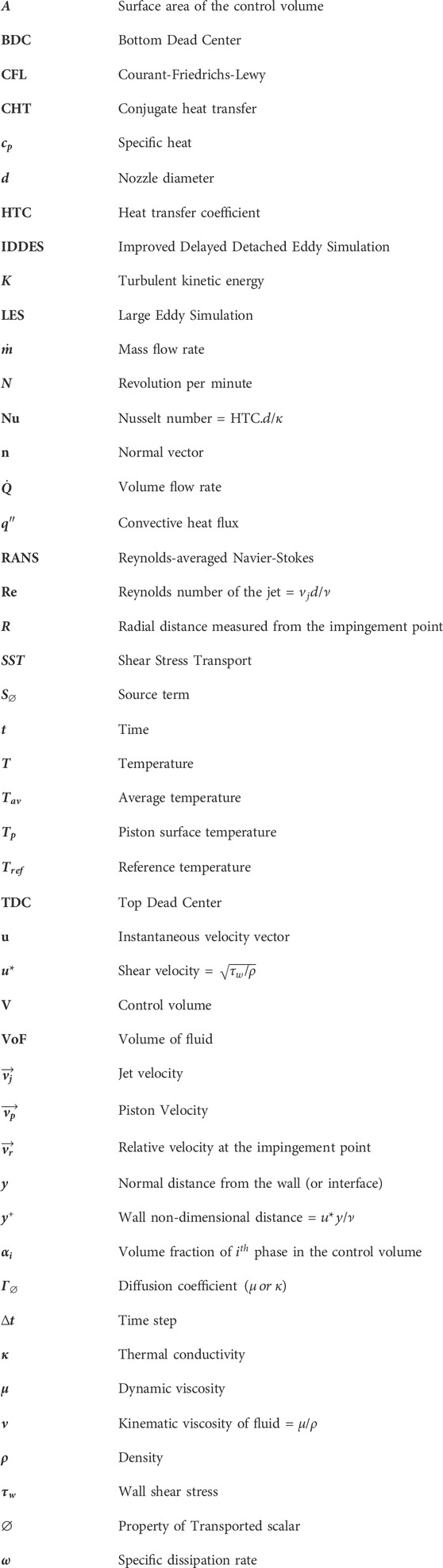
Nomenclature
Keywords: cooling jet, piston cooling enhancement, reciprocating motion, Nusselt number, CFD
Citation: Nasif G, Shinneeb A-M and Balachandar R (2024) Cooling enhancement for engine parts using jet impingement. Front. Mech. Eng 10:1251587. doi: 10.3389/fmech.2024.1251587
Received: 01 July 2023; Accepted: 08 January 2024;
Published: 18 January 2024.
Edited by:
Amin Paykani, Queen Mary University of London, United KingdomReviewed by:
Akshoy Ranjan Paul, Motilal Nehru National Institute of Technology Allahabad, IndiaJinlong Liu, Zhejiang University, China
Copyright © 2024 Nasif, Shinneeb and Balachandar. This is an open-access article distributed under the terms of the Creative Commons Attribution License (CC BY). The use, distribution or reproduction in other forums is permitted, provided the original author(s) and the copyright owner(s) are credited and that the original publication in this journal is cited, in accordance with accepted academic practice. No use, distribution or reproduction is permitted which does not comply with these terms.
*Correspondence: G. Nasif, bmFzaWZnQHV3aW5kc29yLmNh