 S. S. Shahrokhi1
 M. Taeibi Rahni
- 1Department of Aerospace Engineering, Sharif University of Technology, Tehran, Iran
- 2Department of Electromechanical Engineering Technology, California State Polytechnic University-Pomona, Pomona, CA, United States
Introduction: The objective of this study is to develop and simulate a double slotted morphed flap with the intention of reducing drag and enhancing lift, thereby leading to a smaller flap size and reduced weight.
Methods: A flap was meticulously designed to accommodate conditions at Mach 0.2 and Reynolds numbers of 4.7×10⁶. To conduct the simulation, ANSYS FLUENT flow solver and POINTWISE grid generator were utilized. The morphing technique employed involved adjusting both flap mean camber and flap slots, ensuring minimal flow interferences. By discretizing the flap mean camber line, various flap geometries were achieved.
Results and Discussions: The findings reveal a significant enhancement in the airfoil’s aerodynamic efficiency attributed to the implementation of the new flap design. The study shows that utilizing double-slotted morphing in the NACA 4412 airfoil at a 30° flap deflection angle increased the lift coefficient by 82% compared to the un-morphed state. A comparison of lift coefficients between this research and the NACA 4412 split flap at a 60° deflection angle indicates that the double-slotted morphing in the NACA 4412 airfoil at a smaller deflection angle of 30° results in a 14% higher maximum lift coefficient.
1 Introduction
In recent years, there has been a notable increase in the advancement of active flow control actuators in the fields of fluid mechanics and aerodynamics. Plasma actuators (Mirzaei et al., 2012; Taleghani et al., 2012; Salmasi et al., 2013; Mohammadi and Taleghani, 2014; Taleghani et al., 2018) have demonstrated their effectiveness in enhancing aerodynamic performance by increasing lift, reducing drag, and controlling vortex shedding. This is achieved by ionizing the air near the aerodynamic surfaces, generating a micro-jet in close proximity to the surface, and utilizing a fast time response capability.
Surface acoustic waves have been utilized to manipulate water droplets on solid surfaces (Sheikholeslam Noori et al., 2020a; Sheikholeslam Noori et al., 2020b; Noori et al., 2020; Sheikholeslam Noori et al., 2021). They have been proposed as a potential technique to prevent water droplet icing on aircraft wings in areas not covered by the anti-ice system (Taeibi Rahni et al., 2022). Furthermore, fluidic actuators can inject momentum into low momentum areas, providing significant benefits (Abdolahipour, 2023). Abdolhaipour et al. have introduced a novel type of pulsed jet, known as a modulated pulse jet (Abdolahipour et al., 2021; Abdolahipour et al., 2022a; Abdolahipour et al., 2022b), and experimentally applied it as a hybrid active control method on the flap of a high-lift device with a supercritical airfoil section to improve the wing’s aerodynamic performance.
In addition to the rapid progress in flow control actuators, morphing wings have emerged as a promising flow control approach due to their lightweight nature and adjustable stiffness (Xiao et al., 2022). In the realm of aviation, morphing encompasses alterations in wing span, sweep angle, twist angle, dihedral/anhedral angles, camber line, and airfoil thickness. The aim of morphing is to enhance the performance of vehicles at different flight conditions. The aircraft exhibits varying aerodynamic characteristics in different flight conditions, including the distinct aerodynamic conditions experienced during ground effect (Shams Taleghani et al., 2020). Generally, aircrafts are designed to meet specific flight requirements, but when equipped with the ability to modify their geometry during flight, they can adapt to varying conditions and achieve exceptional performances.
To simplify the design of a morphed flap, a framework for different cruise conditions has been introduced in reference (Steenhuizen and van Tooren, 2012). Additionally, in order to enhance lift, reference (Nemati and Jahangirian, 2020) proposed a robust airfoil parameterization method for designing morphed leading and trailing edges.
Researchers have examined the aerodynamic characteristics of morphed flaps, focusing on both trailing-edge and leading-edge flaps. For example, reference (Taguchi et al., 2020) investigated the aerodynamic characteristics of a passive morphed trailing edge in a 2D wing, revealing a higher lift coefficient for the morphed airfoil. In reference (Magrini and Benini, 2017), a GA-(w)-1 airfoil with a 25% morphed leading edge was studied, demonstrating a significant reduction in drag with a slight increase in lift. Furthermore, reference (Abdessemed et al., 2018) investigated the aerodynamic performance of a NACA0012 airfoil with a time-dependent morphed trailing edge, using computational fluid dynamics (CFD), showing a 6.5% increase in aerodynamic efficiency. The effects of morphed leading and trailing edge flaps were also analyzed in reference (Aziz et al., 2019), using ANSYS FLUENT, highlighting substantial improvements in aerodynamic characteristics. Moreover, reference (Rivero et al., 2021) conducted a wind tunnel test on a NACA23012 airfoil with three configurations: base airfoil, hinged flap, and FishBAC morphed flap.
In the case of 3D wings, the aerodynamic performance of a morphed trailing edge was investigated in reference (Lyu and Martins, 2015) to explore the benefits of morphing technology. The results demonstrated a 1% reduction in drag at design and 5% reduction in off-design conditions (along with a 1% reduction in cruise fuel consumption). Reference (Burdette and Martins, 2018) illustrated that adjusting the frequency of motion of a dynamic morphed surface could effectively mitigate separation zones.
Most recently, inspired from owl’s wings, reference (Harbi Monfared et al., 2022) thoroughly investigated a morphed wing from both aerodynamic and aeroacoustics points of view. Furthermore, some efforts have been done to find the best airfoil geometry for various flight conditions. In this field, an aerodynamic shape optimization using CFD was performed in reference (Secanell et al., 2006), wherein they found the best initial airfoil configuration. Their results show that the optimum airfoil configuration has a significant improvement in the performance of a UAV’s. In addition, reference (Fincham and Friswell, 2015) studied optimization of an airfoil camber line in two different configurations.
In addition, morphing technology has shown the ability of delaying flow separation. In this way, reference (Chandrasekhara et al., 1998) investigated a morphed airfoil, in which the radius of its leading edge was adjustable. On the other hand, reference (Jones et al., 2018) illustrated that by adjusting the frequency of motion of a dynamically morphed surface, it is possible to eliminate the separation zone.
Morphing technology has not only improved aircraft performance, but also showcased potential for implementation in wind turbines. According to reference (Ai et al., 2019), morphed flaps provide excellent control over aerodynamic lift in turbine blades. Similarly, reference (Daynes and Weaver, 2012) focused on controlling the aerodynamic load of wind turbine blades, using morphed trailing edge flaps. They designed a morphed flap structure and conducted aeroelastic investigations, which revealed that their morphed flap, with approximately 30% less deflection compared to a conventional flap, could generate the same lift.
Furthermore, various intriguing studies have explored the vibration effects of morphed trailing edges on airfoils. Reference (Simiriotis et al., 2018) demonstrated through numerical and experimental analysis that vibration frequency has the potential to enhance aerodynamic performance and reduce noise. In a similar work focused on a transonic regime, reference (Tô et al., 2019) investigated the effects of upward motion and vibration of a trailing edge, resulting in reduced buffet and a significant increase in lift-to-drag ratio.
In this study, we aim to design a trailing edge flap with morphable camber. Additionally, we need to design two slots that minimize flow interferences. One major challenge with conventional flaps is the generation of considerable noise and drag when deployed due to vortices produced in the cove sections of their slots. Reference (Jawahar et al., 2019) experimentally demonstrated the noise reduction effect of filling the slat cove for a 30P30N airfoil. This problem also arises during retraction due to the discontinuity of wing control surfaces. Moreover, in deflected positions, conventional flaps exhibit sharp changes in geometry, resulting in poor flow quality in those regions.
In order to achieve practical morphed flaps, we have designed a mechanism capable of simultaneously changing flap camber and generating two slots. Subsequently, aerodynamic shapes were designed based on this mechanism. It is important to note that this article solely focuses on investigating the aerodynamic specifications of a morphed flap and thus the structural aspects related to this mechanism are not addressed here.
2 Solution methodology
According to reference (Abbott and Von Doenhoff, 1956), the well-documented NACA4412 airfoil was selected to be investigated in this study.
2.1 Airfoil and its flap geometry
In this study, the auxiliary spar is positioned at 63% of the airfoil chord from the leading edge, as illustrated in Supplementary Figure S1 To generate the morphed section (Supplementary Figure S2), the flap chord is divided into 12 vertical lines (ribs). Here, the intersections of the ribs with the camber line are referred to as discretized camber line points (DCLP). The camber line is then approximated by straight lines connecting the DCLPs, with each straight line, forming an angle with its adjacent line. Considering the flap’s upper and lower surfaces and ribs as a four-bar mechanism, altering the angle of the discretized camber lines results in different flap geometries. Supplementary Figure S3 demonstrates the variation of camber lines obtained using this mechanism, while Supplementary Figure S4 represents the corresponding flap geometries.
2.2 Flap nomenclature
The flap nomenclature in this study is based on the position of maximum camber (x/c') and its maximum value (t/c') relative to the flap chord (Supplementary Figure S5). As depicted in Supplementary Figure S6, our flap is named TnCy, where Tn represents t/c' = n × 100, and Cy denotes the curve number proportional to x/c' with values ranging from 1 to 5. Supplementary Table S1 provides the curve numbers and their corresponding x/c' values.
2.3 Channels
To create channels, the flap’s upper surface is cut at nodes 2 and 8, while the lower surface is cut at nodes w and 4 (Supplementary Figure S2). This division results in three parts: the main airfoil body and flap parts 1 and 2. The downward vertical movement of parts 1 and 2 generates inlets and outlets of the slots (Figure 1). The slots function as channels to transfer and accelerate air from the lower surface of the flap to the upper, thereby preventing separation. The adaptability of the inlet is presumed to play an important role in facilitating smooth airflow transfer, while it is expected that the outlet area remains parallel to the flap’s upper surface (to ensure airflow attachment). Consequently, the angles of the channel walls are adjustable. As depicted in Figure 1, designing the walls of the channels involves obtaining the optimum curves between the nodes (AB and CD in channel No. 1; EF and GH in channel No. 2). This aspect is of considerable importance. The airfoil comprises three parts: the airfoil body, flap parts 1 and 2, and the nearest channel to the main airfoil in channel No. 1. Note, here the area covering the slot which opens during deflection is called Kool (shoulder).
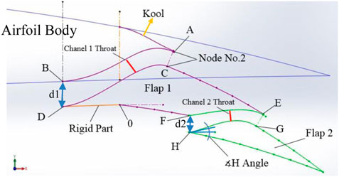
FIGURE 1. Morphed flap parts, including its channels.
Supplementary Figure S7 illustrates three different flaps with the same maximum camber, but with different maximum camber positions. Note, when going from left to right in this figure, the maximum camber position moves towards the trailing edge.
The parameters of the morphed flap are as follows:
1. Size of the maximum camber (t/c'),
2. Position of the maximum camber (x/c'),
3. Inlet geometry of channels with A, D, F, and H angles,
4. Outlet geometry of channels,
5. Profile of channels, and
6. Position of channels’ throat.
3 CFD setup
In this study, incompressible flow at Mach 0.2 and at Reynolds number of 4.7×10⁶ was assumed. The solution was obtained using ANSYS FLUENT software. The pseudo-compressibility method with Roe’s second-order flux splitting method was employed. Additionally, the transition SST turbulence model was used to accurately predict the transition location and thus to improve the accuracy of the drag coefficient. In addition, no-slip walls and pressure far-field boundary conditions were applied.
3.1 Computational grid
Grid generation was performed using POINTWISE software. An O-type domain with a radius of 25c was utilized. The airfoil cell size at the leading edge was set to be 0.0001c to capture high-gradient zones accurately. The cell size at the flaps’ leading and trailing edges was set to be 1.047e-6c. The height of the first cell was chosen to achieve a y + value of 0.8. The quality of the grid was assessed based on mesh orthogonality, skewness, aspect ratio, etc. The number of cells in the boundary layer, wake zone, and far field was optimized to maintain a consistent lift coefficient (optimal number of cells was 210,000). Figures 2, 3 show the details of the grid and its resolution study.
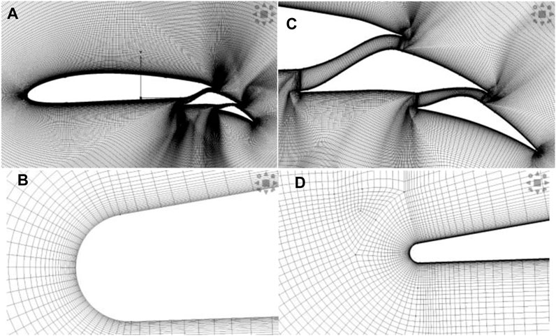
FIGURE 2. Grid details around: (A) the whole airfoil (B) the leading edge of flap number 1 (C) the morphed flap (D) the leading edge of flap number 2.
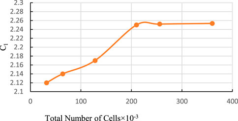
FIGURE 3. Grid resolution study.
3.2 Code validation
For code validation, numerical simulations were performed for the NLR7301 airfoil, which has been previously studied experimentally in reference (Vandenberg and Oskam, 1980). Figure 4A shows a comparison of the pressure coefficient (Cp) between the numerical solution of this work and the experimental data. The present lift and drag coefficients differ from the corresponding experimental data by less than about 5 percent. Figure 4B displays the velocity field around the NLR7301 airfoil. The velocity contour depicted in this figure exhibits identical characteristics to the numerical simulation conducted in reference (Narsipur et al., 2012).
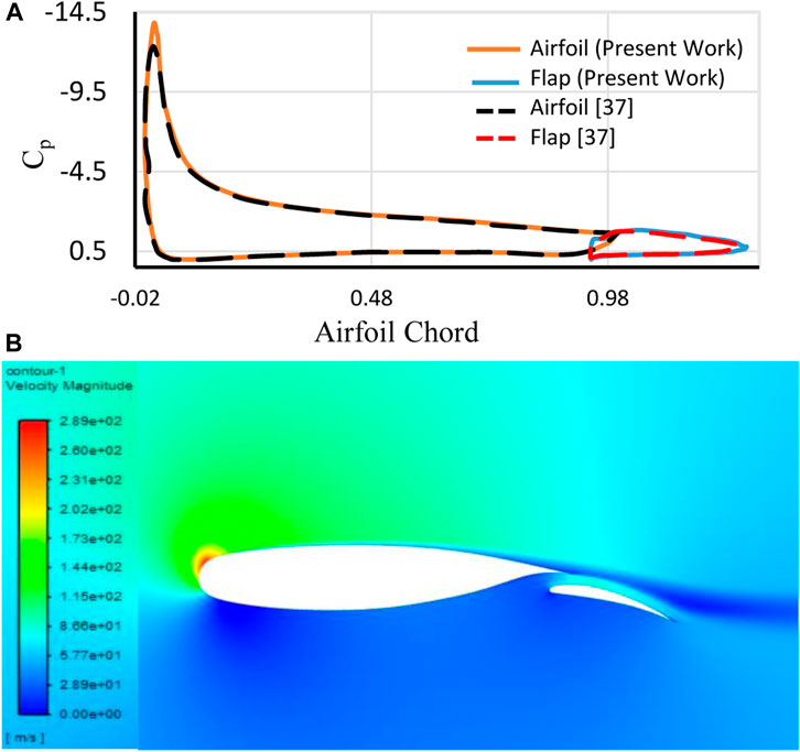
FIGURE 4. (A) Cp comparison between numerical solotion of the peresent work and the expemental data of reference (Vandenberg and Oskam, 1980) and (B) present velocity field around NLR7301 airfoil (at 13.1° angle of attack).
4 Aerodynamic design
In this section, channel parameters are defined and then, while maintaining the optimal channel geometry, various flap cambers at three different angles of attack and two distinct flap deflection angles are investigated.
4.1 Channels’ aerodynamic performance
Figure 5 compares the velocity contour of the morphed flap in two different configurations (with and without channels) at a 5° angle of attack. In the configuration without channels, a large separation zone is observed (even at low angles of attack). By deploying channels, a jet flow is formed, and the separation region disappears, resulting in a significant increase in lift. However, drag nearly remains the same in both configurations. Note, in the configuration without channels, drag is mainly caused by high pressure resulting from separation. With channels, separation is minimized, and thus the pressure drag is considerably reduced (but the channels themselves become the main sources of drag). These two sources of drag appear to have significant interactions, resulting in a relatively consistent total drag. Table 1 presents the aerodynamic characteristics of the two configurations. The pitching moment coefficient is calculated about the quarter-chord point.
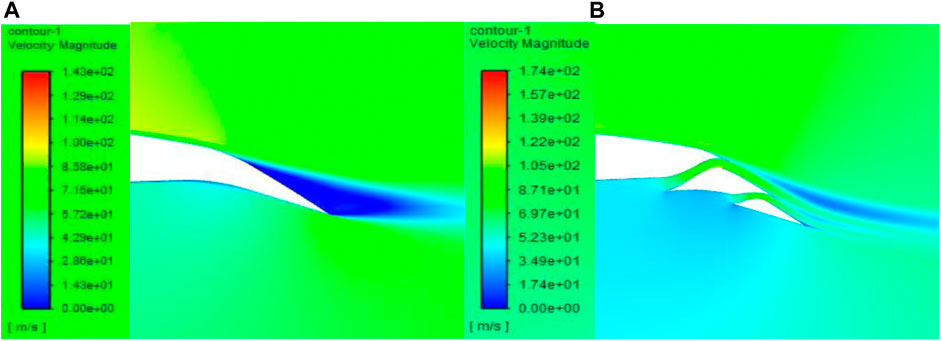
FIGURE 5. Velocity field of the morphed flap: (A) without channel and (B) with channel.
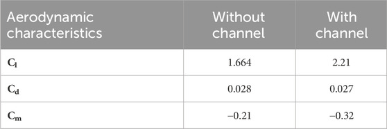
TABLE 1. Aerodynamic characteristics of the morphed flap in two different configurations of “with” and “without” channels.
4.2 Channel shape investigation
The following tests were conducted to design the channels’ shapes at three different angles of attack: 0°, 5°, and 10°, to analyze the intake of channels. Notation “∡A” represents the angle of the channel wall with respect to the horizon at point “A” (e.g., the angle of point “H” in Figure 1). The following cases were studied:
case 1. intake angle suitable for AOA = 0°:
∡B = ∡D = ∡F = ∡H = 0°, case 2. Intake angle suitable for AOA = 5°:
∡B = ∡D = ∡F = ∡H = 5°, case 3. Intake angle suitable for AOA = 10°:
∡B = ∡D = ∡F = ∡H = 10°, case 4. angle of the lower wall is 10° and the upper wall is tangent to the airfoil surface:
∡D = ∡H = 10°.
∡B = ∡F = tangent to the airfoil surface, and
case 5. angle of the lower wall is 10° and angle of the upper wall is 5°:
∡D = ∡H = 10°.
∡B = ∡F = 5°.
Figure 6 displays the aerodynamic characteristics of these cases, in which case 3 demonstrates the best performance. (Figures 7A, C) depict the velocity field of case 1, where even at zero angle of attack, a separation region is present in the leading edge of flaps 1 and 2, resulting in reduced aerodynamic performance. As the inlet angle increases (cases 2 and 3), this separation region becomes smaller, leading to a reduction in drag. (Figures 7, D) present case 3 at 10° and 0° angles of attack, respectively. Increasing the inlet angle causes the channel throat to move towards the outlet, resulting in an increase in lift. Case 4 exhibits the worst performance due to the channel profile moving the throat towards the inlet. Apart from the aerodynamic advantages of the fixed inlet shape in case 3, it also reduces the related mechanism’s complexity, production cost, and the overall weight of the airfoil.
The channels’ profiles were studied considering the following cases:
1. Normal case, with d1 being 3 and d2 being 2 percent of the airfoil’s chord,
2. Case 6, similar to the normal case, but with a 25 percent decrease in both d1 and d2,
3. Case 7, similar to the normal case, but with a 25 percent increase in both d1 and d2, and
4. Case 8, where the throat of the channel is moved towards the outlet.
Figure 8 demonstrates that increasing the width of the channel leads to an increase in lift and a decrease in drag until an optimum point is reached. Further increasing the channel width reverses these effects. Additionally, increasing the channel width results in an increase in the moment coefficient, which does not reverse. Moving the throat towards the outlet increases lift, drag, and pitching moment, but reduces aerodynamic efficiency. The normal case exhibits the highest aerodynamic efficiency (lift-to-drag ratio), while case 6 shows the lowest.

FIGURE 6. Aerodynamic characteristics of the channels’ intake versus angle of attack. (A) Cl, (B) Cd, (C) l/d, and (D) Cm.
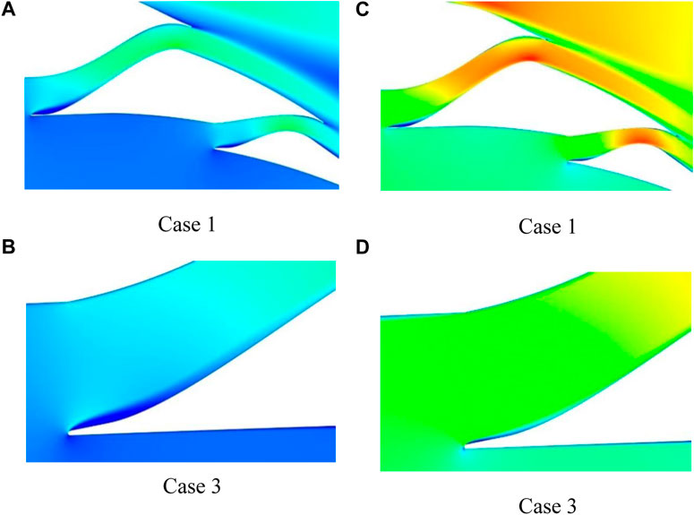
FIGURE 7. Channels’ intake velocity fields at different intake angles and at: (A) and (B) AOA = 10°; (C) and (D) AOA = 0°.
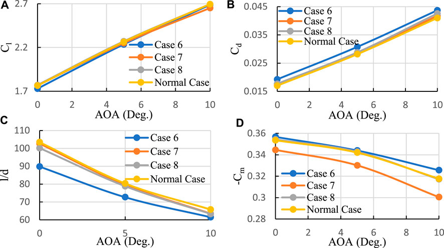
FIGURE 8. Aerodynamic characteristics versus AOA of channels’ profile: (A) Cl, (B) Cd, (C) l/d, and (D) Cm.
4.3 Morphed flap at 15 degrees deflection
(Figures 9A–C) illustrate the lift coefficient versus maximum camber position for three different maximum camber values and three different angles of attack (0°, 5°, and 10°). When the maximum camber position is moved towards the trailing edge, the lift coefficient initially increases and then decreases, with the best position being at 50 percent of the flap chord. Increasing the maximum camber at a fixed maximum camber position also results in an increase in Cl.
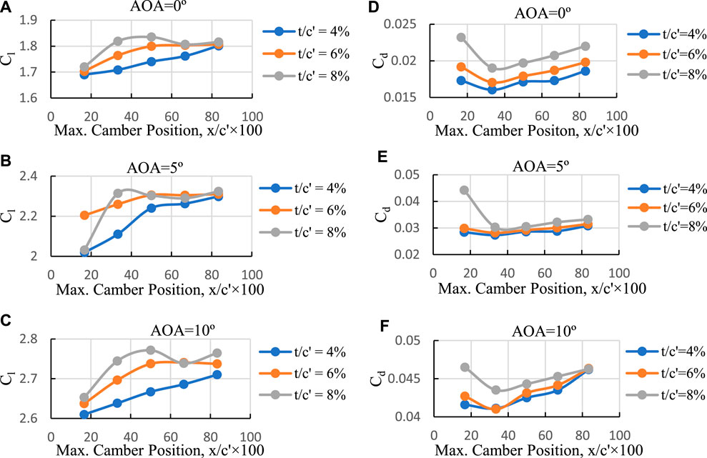
FIGURE 9. Cl and Cd versus maximum camber position for three different maximum cambers and three different angles of attack. (A) AOA = 0°, (B) AOA = 5°, (C) AOA = 10°, (D) AOA = 0°, (E) AOA = 5°, (F) AOA = 10°.
(Figures 9D–F) represent changes in drag coefficient with maximum camber position for three different maximum camber values and three different angles of attack (0°, 5°, and 10°). Moving the maximum camber position towards the trailing edge leads to an increase in Cd. At a fixed maximum camber position, increasing maximum camber causes Cd to increase (independent of the angle of attack). The maximum camber position at 16.67 percent exhibits a cove that creates a dead air area, resulting in a large Cd value. Increasing maximum camber further increases both the dead air area and Cd. The maximum camber position at 33.33 percent with a camber of 4 percent shows the minimum Cd, regardless of the angle of attack.
For x/c' = 66.67 percent, both Cl and Cd are lower than those for x/c' = 83.33 percent due to an effect called hook-like (Supplementary Figure S8). This effect occurs when the camber position moves to 83.33 percent of the flap chord, resulting in an aerodynamic behavior similar to a gurney flap of references (Papadakis et al., 1996; Papadakis et al., 1997), leading to higher Cl and Cd.
(Figures 10A–C) depict aerodynamic efficiency versus maximum camber position for three different maximum cambers and for three different angles of attack. The optimal lift-to-drag ratio is found to be independent of maximum camber position and angle of attack always occurring at 33.33 percent of the flap chord (curve No. 2; C2). Generally, increasing maximum camber reduces l/d and the difference in l/d for various camber values decreases at higher angles of attack.
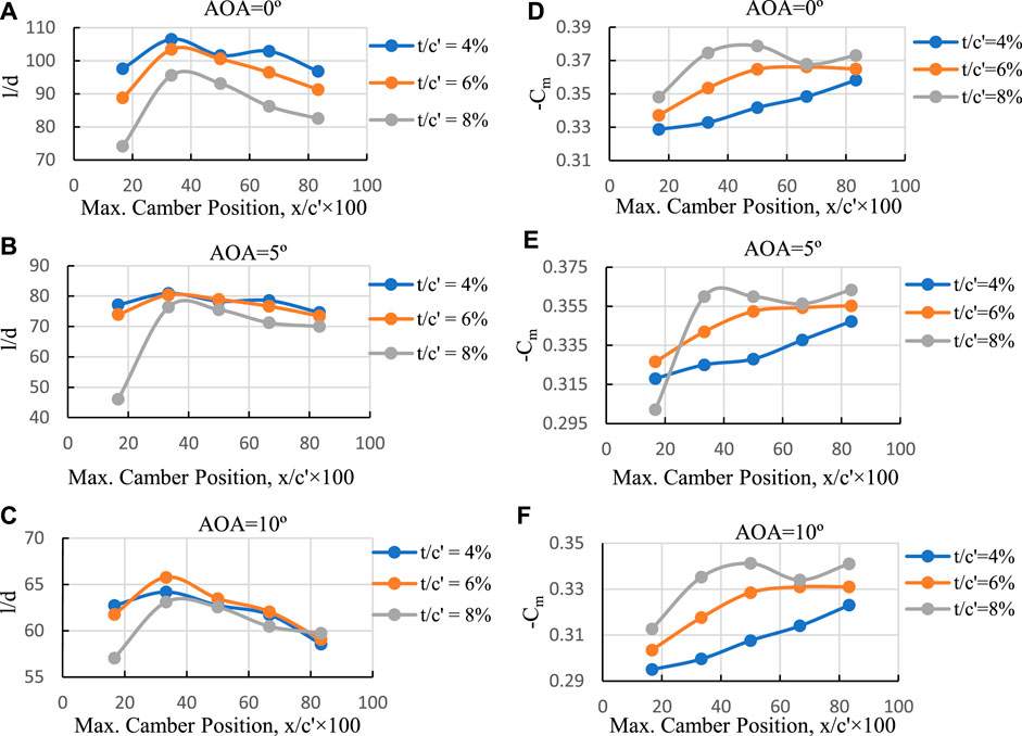
FIGURE 10. l/d and Cm versus camber position for three different camber values and for three distinct angles of attack. (A) AOA = 0°, (B) AOA = 5°, (C) AOA = 10°, (D) AOA = 0°, (E) AOA = 5°, (F) AOA = 10°.
(Figures 10D–F) demonstrates the pitching moment coefficient versus maximum camber position for three different maximum cambers and for three different angles of attack. Cm behaves similarly to Cl, showing a hook-like effect as well. Lower maximum camber values result in lower Cm. Moving the camber position towards the flap’s leading edge leads to a smaller Cm. The minimum Cm is associated with the maximum camber position closest to the flap’s leading edge.
Supplementary Tables S2, S3 provide the best and worst camber positions and camber values for various aerodynamic characteristics, respectively. The desired flap geometry for each aerodynamic specification is also listed.
Figure 11 presents a comparative analysis of four distinct desired flaps, demonstrating a reduction of approximately 5 percent in the l/d difference at higher angles of attack. It is important to note that the selection of flaps may vary depending on the aircraft and its flight type. For example, during take-off and landing configurations, quantities related to higher angles of attack hold significant importance. In such scenarios, emphasis is placed more on Cl rather than Cd, Cm, and l/d. Consequently, the T8C3 flap is considered suitable for shorter runways.
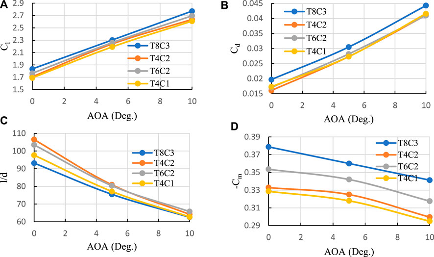
FIGURE 11. Comparison of aerodynamic performance for four desired morphed flaps. (A) Cl, (B) Cd, (C) l/d ratio, and (D) Cm.
To provide a practical example, let’s consider an aircraft that prioritizes drag reduction. Despite the higher Cl value of the T8C3 flap, an aircraft with specifications M = 300tons, SW = 511 m2, AR = 7, and e = 0.8 lead to a take-off speed that is 3.28 km/h higher compared to the T6C3 flap. However, the T8C3 flap results in 3 percent higher drag force. On the other hand, the T4C2 flap exhibits a take-off speed that is 5.4 km/h higher, but a drag force that is 4.5 percent lower than that of the T8C3 flap. Additionally, the T4C2 flap’s smaller Cm leads to a reduced size of the horizontal tail, resulting in less drag and a negative lift force.
Figure 12 showcases the Cp distribution of the T8C3 flap, where fluctuations in Cp are observed on the upper surface of the flaps. These fluctuations are likely a result of interactions between the separation zone and the jet flow formed by the channels, leading to a mixing layer flow.
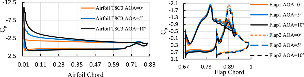
FIGURE 12. Cp distribution of the flap T8C3 for three different angles of attack.
Figure 13 provide insight into the velocity field of the T8C3 flap. The geometry exhibits a separation zone at the trailing edge of flap No. 2. As the angle of attack increases, the separation zone remains constant due to the presence of the jet flow formed by channel No. 2, which inhibits separation. This behavior persists until the angle of attack reaches a limit where flow separation occurs at the Kool area.
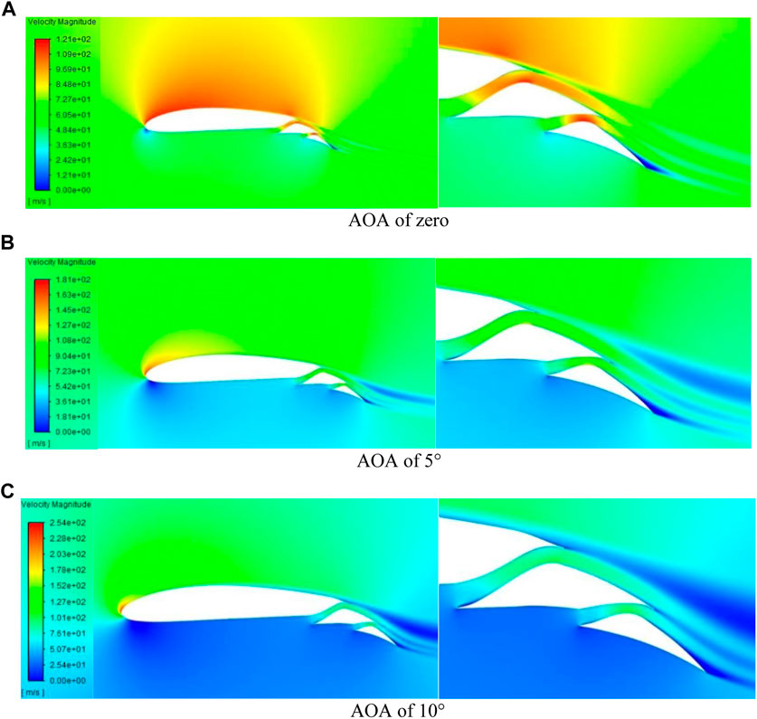
FIGURE 13. T8C3 flap velocity field at AOA of 0, 5° and 10°. (A) AOA of zero, (B) AOA of 5°, (C) AOA of 10°
4.4 Morphed flap at 30 degrees deflection
At 30° flap deflection, Figures 14A–C depict the relationship between maximum camber position and Cl for two different maximum cambers and three different angles of attack. At this deflection angle, the camber position that yields maximum Cl shifts towards the trailing edge, precisely at half the flap chord (x/c' = 50%). It should be noted that a maximum camber of 6 percent, compared to 8 percent at zero angle of attack, demonstrates superior performance. However, as the angle of attack increases, a reversing phenomenon occurs. The reason behind this is that the lower maximum camber (6 percent) causes the Kool area to have larger angles relative to the flow, resulting in enhanced flow separation. Moreover, a flap with 6 percent maximum camber at 7° angle of attack experiences a deep stall.
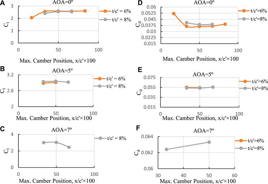
FIGURE 14. Cl and Cd versus camber position for three different cambers at three different angles of attack (at 30° Deflection). (A) AOA = 0°, (B) AOA = 5°, (C) AOA = 7°, (D) AOA = 0°, (E) AOA = 5°, (F) AOA = 7°.
(Figures 14D–F) showcase Cd versus maximum camber position for two different maximum cambers and three different angles of attack. Similar to Cl, the reversing phenomenon is observable here as well. While maximum camber position movement has a minimal impact on drag value, it generally leads to an increase in Cd as it approaches the trailing edge. For angles of attack below stall, the optimal maximum camber position is at the flap mid chord.
Figure 15, presented in panels a) to c), illustrates the relationship between l/d and maximum camber position for two different maximum cambers at three distinct angles of attack. Similar to Cl and Cd, smaller maximum camber values exhibit better performance at lower angles of attack. Although the movement of the maximum camber position has a slight impact on l/d, generally, when it shifts towards the trailing edge, l/d decreases. In comparison to the 15° deflection, the position of maximum l/d has shifted from 33.33 to 50 percent of the flap chord.
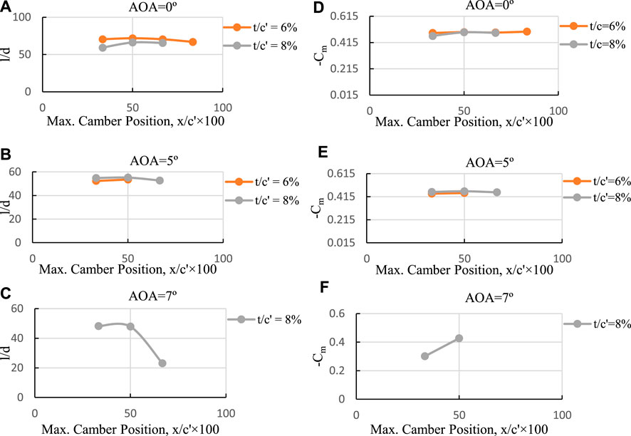
FIGURE 15. l/d and Cm versus maximum camber position for three different maximum cambers at three angles of attack (at 30° deflection). (A) AOA = 0°, (B) AOA = 5°, (C) AOA = 7°, (D) AOA = 0°, (E) AOA = 5°, (F) AOA = 7°.
(Figures 15D–F) depict the behavior of Cm in relation to maximum camber position. The behavior of Cm aligns with other aerodynamic characteristics. For instance, there is a small difference between the 6 percent and 8 percent maximum camber values, and a reversing phenomenon is observed as well.
Figure 16 provide a comparison of the aerodynamic performance of flaps with varying maximum camber position. It is evident that the flap maximum camber position located in the middle of the flap chord yields the best performance. Hence, for the 30° morphed flap deflection, the desired configuration is the T8C3 flap.
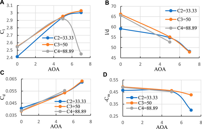
FIGURE 16. (A) Cl, (B) l/d versus angle of attack, (C) Cd, and (D) Cm versus AOA when t/c'×100 = 8 and x/c' varies from 33.33 to 88.89 percent.
Figure 17 displays Cp distribution over the airfoil surface for three different angles of attack, highlighting the fluctuations resulting from the mixing layer flow on the upper surface of the flap.
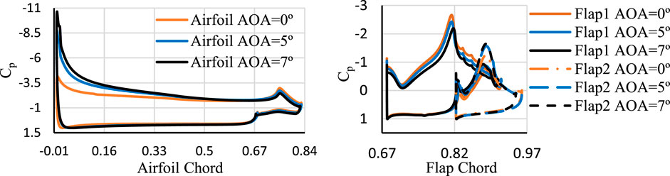
FIGURE 17. Cp for 30° deflection of the flap T8C3 at three different angles of attack.
Figure 18 showcase the flow field, even at zero angle of attack, indicating a separation zone at the trailing edge of flap “2”due to the steep slope of the upper surface in that area. Additionally, a larger dead region is observed at the leading edge of flap “1”caused by the alteration in the channel path, where the separated flow needs to travel a longer distance to reach the channel wall. In all angles of attack, the presence of the jet flow generated by channel number 2 maintains the trailing edge separation unchanged. At 7° angle of attack, corresponding to the stall angle of attack, separation initiates at the flap Kool area.
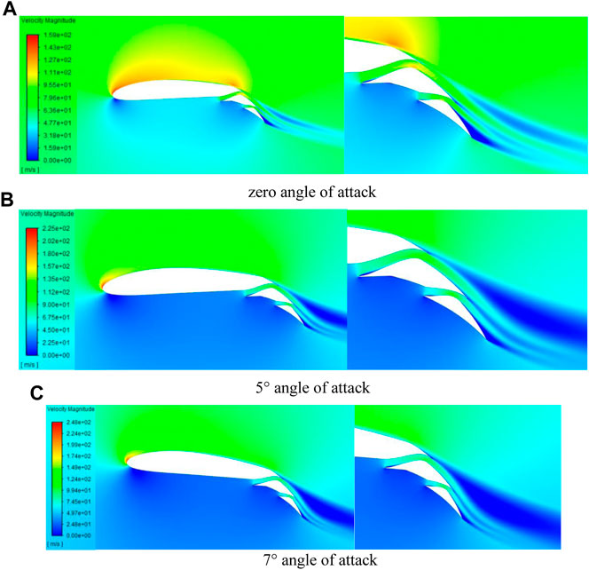
FIGURE 18. Velocity Field of the T8C3 flap at 0, 5°, and 7°. (A) zero angle of attack, (B) 5° angle of attack, (C) 7° angle of attack.
4.5 Modified T4C3 flap at 30 degrees deflection
(Figure 19A) demonstrates that even at zero angle of attack, flow separation occurs for the T4C3 flap. To delay separation in the Kool zone, modifications were implemented. Reducing the angle of the Kool zone increases the outlet width of channel “1,” and thus, a third part was added to maintain the outlet width unchanged. Furthermore, to reduce the length of the Kool zone, the outlet of channel “1” was shifted from node number 2 to node number 1. (Figure 19B) visually presents the related changes, and Table 2 provides the results of the geometry modifications.
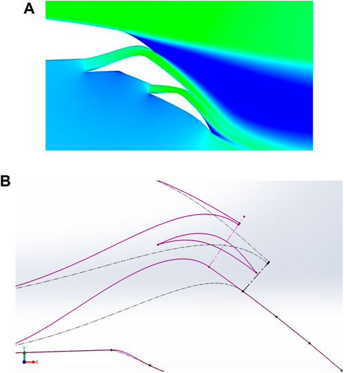
FIGURE 19. (A) Separation in Kool area and (B) Modified flap geometry (purple lines) and base line (dash-dotted lines).
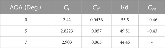
TABLE 2. Modified flap aerodynamic specifications.
Figure 20 compares the aerodynamic characteristics of the T8C3 and modified T4C3 flaps. Although the T8C3 flap outperforms the T4C3 flap in terms of aerodynamic performance, it is worth considering that the T8C3 flap has an 8 percent maximum camber, resulting in a larger Cl. However, when considering Cl, the T4C3 flap exhibits a better improvement compared to the T8C3 flap, along with an increased stall angle of attack.
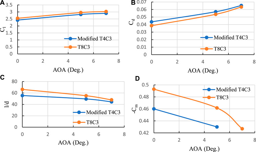
FIGURE 20. Aerodynamic characteristics comparison of the modified and T8C3 flaps. (A) Cl, (B) Cd, (C) l/d, and (D) Cm.
Figure 21 showcase the velocity field of the modified T4C3 flap, clearly illustrating the disappearance of separation. It is important to note that the addition of an extra part to the morphed flap introduces challenges related to increased weight, cost, and production complexities.
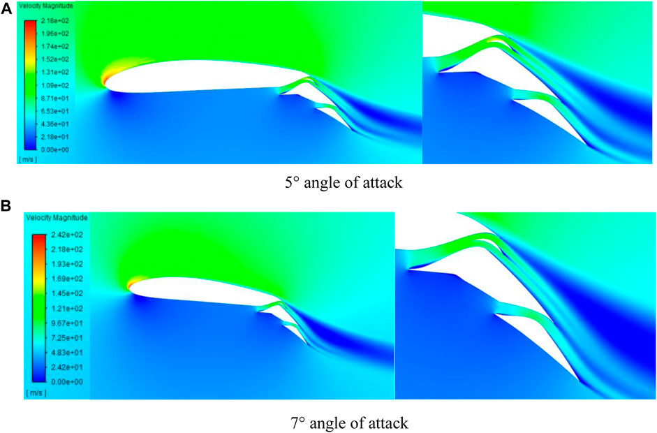
FIGURE 21. Modified flap velocity field. (A) 5° angle of attack, (B) 7° angle of attack
5 Concluding remarks
Figure 22 examines the application of a morphed flap on the NACA4412 airfoil, comparing it to a regular flap with a deflection angle of 60°. The study investigates two different deflection angles: 15° and 30°. Remarkably, despite the morphed flap having a maximum deflection angle of 30°, its performance surpasses that of the regular flap. The morphed flap exhibits a significant reduction in drag (approximately three times) and an increase in lift, resulting in a considerable improvement in the l/d ratio (approximately five times). In contrast, both the base airfoil and split flap demonstrate lower Cm values compared to the morphed flap. Table 3 shows the maximum and minimum values for these flaps. It should be noted that the results of un-morphed airfoil of the current research are the same as the results of the simple NACA4412 airfoil in reference (Abbott and Von Doenhoff, 1956).
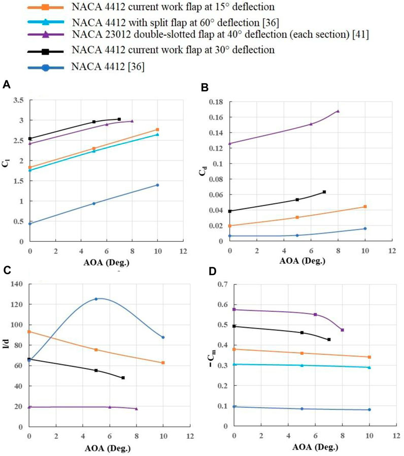
FIGURE 22. Comparison of morphed and conventional flaps: (A) Cl, (B) Cd, (C) l/d ratio, and (D) Cm.
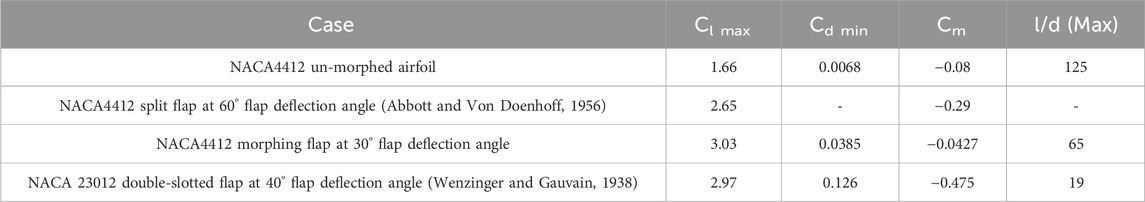
TABLE 3. Comparison of morphed and conventional flaps.
6 Conclusion
In this study, we designed a double-slotted morphed flap with variable camber and slots, using CFD to examine its aerodynamic performance. The characteristics of the channels (slots), including width, throat position, and intake angle, were initially investigated. Subsequently, five different x/c' and three different t/c' were examined. The second step was repeated for two different flap deflections (15° and 30°) at three distinct angles of attack. The optimal flap geometry was determined and a modification was applied to further enhance the flap’s aerodynamic performance. The results demonstrate an increase in lift, a reduction in drag, and a significant improvement in l/d. The maximum lift coefficient at a 30° flap deflection is 3.03, whereas the maximum lift coefficients for the un-morphed airfoil and split flap at a 60° deflection are 1.66 and 2.65, respectively. In other words, the morphed flap generates more lift (about 14% in maximum lift), despite its considerably smaller deflection angle (one of the reasons for its lower drag coefficient). According to the findings, the double-slotted modified flap has enhanced the maximum lift coefficient of the airfoil by 82.5%. While there is no available data for the drag coefficient of the split flap applied to the NACA4412 airfoil, to gain a better understanding of this coefficient, the NACA23012 airfoil with a double-slotted flap has a minimum drag coefficient of 0.126, whereas the present morphed flap exhibits a drag coefficient of 0.068 (more than three times less). Note, compared to the double-slotted flap, the morphed flap achieves a fivefold increase in l/d ratio at zero angle of attack. This study also investigated the pitching moment coefficient, which exhibits behavior similar to Cl, but with different magnitudes. Although the magnitude of Cm for the present morphed flap exceeds that of the split flap, it is lower than that of the double-slotted flap used for the NACA23012 airfoil. It appears that the magnitude of this coefficient is proportional to the lift coefficient, meaning that greater lift results in a higher pitching moment.
7 Future outlook
To enhance the practicality of the research findings, further investigation is necessary to determine the flap’s weight, production cost, and manufacturing feasibility. Additionally, given the critical role of the Kool section in the flap, deeper analysis of this area is recommended. Lastly, additional investigation is suggested to identify the optimal flap shape.
Data availability statement
The original contributions presented in the study are included in the article/Supplementary Material, further inquiries can be directed to the corresponding author.
Author contributions
SS: Investigation, Methodology, Software, Writing–original draft, Writing–review and editing. MT: Conceptualization, Methodology, Supervision, Writing–original draft, Writing–review and editing. PA: Software, Writing–original draft, Writing–review and editing.
Funding
The author(s) declare that no financial support was received for the research, authorship, and/or publication of this article.
Acknowledgments
The authors would like to express their gratitude for the valuable support provided by SS, who supplied the necessary hardware for our CFD work.
Conflict of interest
The authors declare that the research was conducted in the absence of any commercial or financial relationships that could be construed as a potential conflict of interest.
The author(s) declared that they were an editorial board member of Frontiers, at the time of submission. This had no impact on the peer review process and the final decision
Publisher’s note
All claims expressed in this article are solely those of the authors and do not necessarily represent those of their affiliated organizations, or those of the publisher, the editors and the reviewers. Any product that may be evaluated in this article, or claim that may be made by its manufacturer, is not guaranteed or endorsed by the publisher.
Supplementary material
The Supplementary Material for this article can be found online at: https://www.frontiersin.org/articles/10.3389/fmech.2024.1371479/full#supplementary-material
References
Abdessemed, C., Yao, Y., Bouferrouk, A., and Narayan, P. (2018). Morphing airfoils analysis, using dynamic meshing. Int. J. Numer. Methods Heat Fluid Flow 28 (No. 5), 1117–1133. doi:10.1108/HFF-06-2017-0261
Abdolahipour, S. (2023). Effects of low and high frequency actuation on aerodynamic performance of a supercritical airfoil. Front. Mech. Eng. 9, 1290074. doi:10.3389/fmech.2023.1290074
Abdolahipour, S., Mani, M., and Shams Taleghani, A. (2021). Parametric study of a frequency-modulated pulse jet by measurements of flow characteristics. Phys. Scr. 96 (No. 12), 125012. doi:10.1088/1402-4896/ac2bdf
Abdolahipour, S., Mani, M., and Shams Taleghani, A. (2022a). Experimental investigation of flow control on a high-lift wing using modulated pulse jet vortex generator. J. Aerosp. Eng. 35 (5), 05022001. doi:10.1061/(asce)as.1943-5525.0001463
Abdolahipour, S., Mani, M., and Shams Taleghani, A. (2022b). Pressure improvement on a supercritical high-lift wing using simple and modulated pulse jet vortex generator. Flow. Turbul. Combust. 109 (1), 65–100. doi:10.1007/s10494-022-00327-9
Ai, Q., Weaver, P. M., Barlas, T. K., Olsen, A. S., Madsen, H. A., and Andersen, T. L. (2019). Field testing of morphing flaps on a wind turbine blade, using an outdoor rotating rig. Renew. Energy 133, 53–65. doi:10.1016/j.renene.2018.09.092
Aziz, M. A., Mansour, M., Iskander, D., and Hany, D. (2019). Combined droop nose and trailing edges morphing effects on airfoils aerodynamics. SN Appl. Sci. 1 (No. 9), 1033. doi:10.1007/s42452-019-0796-6
Burdette, D. A., and Martins, J. R. (2018). Design of a transonic wing with an adaptive morphing trailing edge via aerostructural optimization. Aerosp. Sci. Technol. 81, 192–203. doi:10.1016/j.ast.2018.08.004
Chandrasekhara, M. S., Wilder, M. C., and Carr, L. W. (1998). Unsteady stall control, using dynamically deforming airfoils. AIAA J. 36 (No. 10), 1792–1800. doi:10.2514/2.294
Daynes, S., and Weaver, P. M. (2012). A morphing trailing edge device for a wind turbine. J. Intelligent Material Syst. Struct. 23 (No. 6), 691–701. doi:10.1177/1045389X12438622
Fincham, J. H. S., and Friswell, M. I. (2015). Aerodynamic optimisation of a camber morphing aerofoil. Elsevier Masson SAS 43, 245–255. doi:10.1016/j.ast.2015.02.023
Harbi Monfared, R., Taeibi Rahni, M., Zareh, M., Ahmadi, G., and Etemadi Haghighi, S. (2022). Aerodynamic and aeroacoustic performance of a wing with structured surface inspired by owl’s wings. J. Appl. Fluid Mech. 15 (4), 1243–1253. doi:10.47176/jafm.15.04.33091
Jawahar, H. K., Theunissen, R., Azarpeyvand, M., and da Silva, C. R. I. (2019). Flow characteristics of slat cove fillers. Aerosp. Sci. Technol. 100. doi:10.1016/j.ast.2020.105789
Jones, G., Santer, M., and Papadakis, G. (2018). Control of low Reynolds number flow around an airfoil, using periodic surface morphing: a numerical study. J. Fluids Struct. 76, 95–115. doi:10.1016/j.jfluidstructs.2017.09.009
Lyu, Z., and Martins, J. R. (2015). Aerodynamic shape optimization of an adaptive morphing trailing-edge wing. J. Aircr. 52 (No. 6), 1951–1970. doi:10.2514/1.C033116
Magrini, A., and Benini, E. (2017). Aerodynamic optimization of a morphing leading-edge airfoil with a constant arc length parameterization. J. Aerosp. Eng. 31 (No. 2). doi:10.1061/(ASCE)AS.1943-5525.0000812
Mirzaei, M., Taleghani, A. S., and Shadaram, A. (2012). Experimental study of vortex shedding control using plasma actuator. Appl. Mech. Mater. 186, 75–86. doi:10.4028/www.scientific.net/amm.186.75
Mohammadi, M., and Taleghani, A. S. (2014). Active flow control by dielectric barrier discharge to increase stall angle of a NACA0012 airfoil. Arab. J. Sci. Eng. 39, 2363–2370. doi:10.1007/s13369-013-0772-1
Narsipur, S., Pomeroy, B., and Selig, M. (2012). “CFD analysis of multi-element airfoils for wind turbines,” the 30th AIAA applied aerodynamics conference. New Orleans: Louisiana. doi:10.2514/6.2012-2781
Nemati, M., and Jahangirian, A. (2020). Robust aerodynamic morphing shape optimization for high-lift missions. Aerosp. Sci. Technol. 103, 105897. doi:10.1016/j.ast.2020.105897
Noori, S. M. S., Taeibi Rahni, M., and Shams Taleghani, S. A. (2020). Numerical analysis of droplet motion over a flat plate due to surface acoustic waves. Microgravity Sci. Technol. 32 (4), 647–660. doi:10.1007/s12217-020-09784-1
Papadakis, M., Myose, R., Heron, I., and Johnson, B. (1996). An experimental investigation of gurney flaps on a ga(W)-2 airfoil with 25% slotted flap. AIAA-96-2437-CP. doi:10.2514/6.1996-2437
Papadakis, M., Myose, R., Matallana, S., Papadakis, M., Myose, R., and Matallana, S. (1997). “Experimental investigation of gurney flaps on a two-element general aviation airfoil,” the 35th Aerospace sciences meeting and exhibit. Reno, NV: U.S.A. doi:10.2514/6.1997-728
Rivero, A. E., Fournier, S., Manolesos, M., Cooper, J. E., and Woods, B. K. (2021). Experimental aerodynamic comparison of active camber morphing and trailing-edge flaps. AIAA J. 59 (No. 7), 2627–2640. doi:10.2514/1.J059606
Salmasi, A., Shadaram, A., and Taleghani, A. S. (2013). Effect of plasma actuator placement on the airfoil efficiency at poststall angles of attack. IEEE Trans. Plasma Sci. 41 (10), 3079–3085. doi:10.1109/tps.2013.2280612
Secanell, M., Suleman, A., and Gamboa, P. (2006). Design of a morphing airfoil, using aerodynamic shape optimization. AIAA J. 44 (No. 7), 1550–1562. doi:10.2514/1.18109
Shams Taleghani, A., Ghajar, A., and Masdari, M. (2020). Experimental study of ground effect on horizontal tail effectiveness of a conceptual advanced jet trainer. J. Aerosp. Eng. 33 (4), 05020001. doi:10.1061/(asce)as.1943-5525.0001140
Sheikholeslam Noori, M., Shams Taleghani, A., and Taeibi Rahni, M. (2020a). Phenomenological investigation of drop manipulation using surface acoustic waves. Microgravity Sci. Technol. 32 (6), 1147–1158. doi:10.1007/s12217-020-09839-3
Sheikholeslam Noori, M., Shams Taleghani, A., and Taeibi Rahni, M. (2021). Surface acoustic waves as control actuator for drop removal from solid surface. Fluid Dyn. Res. 53 (4), 045503. doi:10.1088/1873-7005/ac12af
Sheikholeslam Noori, M., Taeibi Rahni, M., and Shams Taleghani, A. (2020b). Effects of contact angle hysteresis on drop manipulation using surface acoustic waves. Theor. Comput. Fluid Dyn. 34 (1), 145–162. doi:10.1007/s00162-020-00516-0
Simiriotis, N., Jodin, G., Marouf, A., Elyakime, P., Hoarau, Y., Hunt, J. C. R., et al. (2018). Morphing of a supercritical wing by means of trailing edge deformation and vibration at high Reynolds numbers: experimental and numerical investigation. J. Fluids Struct. 91, 102676. doi:10.1016/j.jfluidstructs.2019.06.016
Steenhuizen, D., and van Tooren, M. (2012). The implementation of a knowledge-based framework for the aerodynamic optimization of a morphing wing device. Adv. Eng. Inf. 26 (No. 2), 207–218. doi:10.1016/j.aei.2012.02.004
Taeibi Rahni, M., Shams Taleghani, A., Sheikholeslam, M., and Ahmadi, G. (2022). Computational simulation of water removal from a flat plate, using surface acoustic waves. Wave Motion 111, 102867. doi:10.1016/j.wavemoti.2021.102867
Taguchi, K., Fukunishi, K., Takazawa, S., Sunada, Y., Imamura, T., Rinoie, K., et al. (2020). Experimental study about the deformation and aerodynamic characteristics of the passive morphing airfoil. Trans. Jpn. Soc. Aerosp. Sci. 63 (No. 1), 18–23. doi:10.2322/tjsass.63.18
Taleghani, A. S., Shadaram, A., and Mirzaei, M. (2012). Effects of duty cycles of the plasma actuators on improvement of pressure distribution above a NLF0414 airfoil. IEEE Trans. Plasma Sci. 40 (5), 1434–1440. doi:10.1109/tps.2012.2187683
Taleghani, A. S., Shadaram, A., Mirzaei, M., and Abdolahipour, S. (2018). Parametric study of a plasma actuator at unsteady actuation by measurements of the induced flow velocity for flow control. J. Braz. Soc. Mech. Sci. Eng. 40 (No. 4), 173–213. doi:10.1007/s40430-018-1120-x
Tô, J. B., Simiriotis, N., Marouf, A., Szubert, D., Asproulias, I., Zilli, D. M., et al. (2019). Effects of vibrating and deformed trailing edge of a morphing supercritical airfoil in transonic regime by numerical simulation at high Reynolds number. J. Fluids Struct. 91, 102595. doi:10.1016/j.jfluidstructs.2019.02.011
Vandenberg, B., and Oskam, B. (1980). Boundary layer measurements on a two-dimensional wing with flap and a comparison with calculations. AGARD Turbul. Bound. Layers 14. SEE N80-27647 18-34).
Wenzinger, C. J., and Gauvain, W. E. (1938). Wind-tunnel investigation of a NACA23012 airfoil with A slotted flap and three types of auxiliary flap. NACA Tech. Rep. No 679.
Xiao, L., Zhao, H., Xu, Z., Li, X., Shen, C., Wang, K., et al. (2022). A new architecture of morphing wing based on hyperelastic materials and metastructures with tunable stiffness. Front. Mech. Eng. 7, 814446. doi:10.3389/fmech.2021.814446
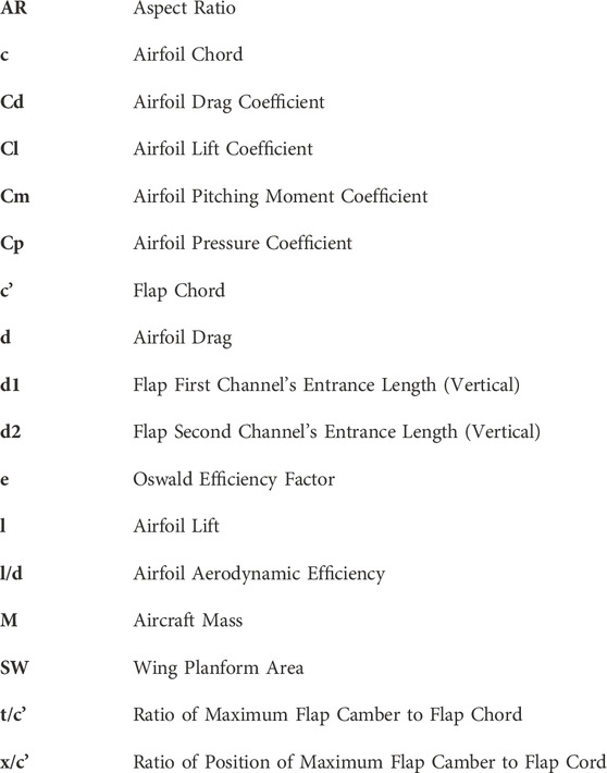
Nomencalture
Keywords: morphing, double slotted flap, CFD, lift, drag, high-lift device, airfoil, flow control
Citation: Shahrokhi SS, Taeibi Rahni M and Akbari P (2024) Aerodynamic design of a double slotted morphed flap airfoil– a numerical study. Front. Mech. Eng 10:1371479. doi: 10.3389/fmech.2024.1371479
Received: 16 January 2024; Accepted: 21 February 2024;
Published: 15 March 2024.
Edited by:
Farschad Torabi, K.N.Toosi University of Technology, IranReviewed by:
Ebrahim Afshari, University of Isfahan, IranArsalan Ghajar, Aerospace Research Center, Iran
Copyright © 2024 Shahrokhi, Taeibi Rahni and Akbari. This is an open-access article distributed under the terms of the Creative Commons Attribution License (CC BY). The use, distribution or reproduction in other forums is permitted, provided the original author(s) and the copyright owner(s) are credited and that the original publication in this journal is cited, in accordance with accepted academic practice. No use, distribution or reproduction is permitted which does not comply with these terms.
*Correspondence: M. Taeibi Rahni, dGFlaWJpQHNoYXJpZi5lZHU=