 Kristopher T. Olshefski
 Gwibo Byun
 John Gillespie
- Advanced Propulsion and Power Laboratory, Virginia Tech, Blacksburg, VA, United States
The present study demonstrates the novel application of a method for assessing particle spatial distribution at the inlet of a gas turbine engine that is undergoing solid particulate ingestion. Termed the Particle Visualization by Illuminated Scattering (ParVIS) technique, this method requires a laser sheet, camera, and in-situ particle feed rate reference measurement to provide imaging-based measurements of integrated particle mass flow and concentration distribution across the illuminated engine inlet plane. This is accomplished by incorporating an in-situ calibration constant that takes into account both the particle mass flow rate and the integrated pixel intensity across the captured region, which exhibits a proportional relationship. For these tests, a Rolls-Royce M250 turboshaft engine was operated at a ground idle condition (air intake mass flow of 0.744 kg/s), and crushed quartz sand was delivered at a maximum average rate of approximately 1.5 g/min. The results show accurate estimations of the injected particle mass flow, with an average root-mean-square error of 0.06 g/min, or 6%, compared to the monitored mass flow value obtained using a precision scale.
1 Introduction
Solid particulate ingestion is an inevitability for aircraft operating in hazardous environments. The presence of these particles may be due to atmospheric dust, volcanic ash, or sand when operating in arid zones. Because particle ingestion has been linked to premature engine wear, this phenomenon is of particular interest to researchers and manufacturers alike. This occurrence has historically had a significant impact on equipment and logistics and, in extreme cases, resulted in loss of life. In December 1989, a KLM Dutch Airlines 747–400 operating near Anchorage, AK, unintentionally flew through the ash cloud of a recent volcanic eruption of Mt. Redoubt, which sent ash more than 30,000 feet into the atmosphere (Neal et al., 1997). The aircraft was equipped with four General Electric CF6-80C2 engines and experienced a four-engine flame-out, which caused the flight crew to make an emergency landing (Daw, 1992). All four engines from the aircraft were replaced, costing the airline over 80 million dollars in replacements and repairs (Miller, 1996). During the Operation Iraqi Freedom period, the United States Army experienced a reduced availability of its CH-47 helicopters due to 75%–95% premature engine failures, which were directly linked to sand ingestion (Brun et al., 2012). In 2010, following the eruption of the Eyjafjallajökull volcano, the subsequent ash cloud led to the total closure of European airspace. This resulted in the cancellation of thousands of flights and an estimated economic impact of nearly $2 billion (Chen and Zhao, 2015). In 2015, an MV-22 Osprey crashed during a training exercise in Hawaii, claiming the lives of two US Marines and injuring twenty other personnel (Whittle, 2015). The cause of the fatal crash was attributed to dust ingestion, resulting in an engine failure.
A substantial effort has been made to understand the effects of particle ingestion on aircraft engines (Olshefski et al., 2022; Potter and Tatam, 1997; Litchford et al., 1998; Dunn, 2012; Tabakoff, 1987; Warwick, 2015; Bird and Grabe, 1991). Much of this work has focused on the impact of particle deposition on turbine sections, blockages of cooling vanes, and the erosion characteristics resulting from particle interactions (Kim et al., 1993; Hamed et al., 2006). Early work by Tabakoff and collaborators investigated the effects of particle impacts on turbomachinery materials, considering variations in particle velocity (Grant and Tabakoff, 1975; Tabakoff and Hamed, 1977; Tabakoff and Vittal, 1983; Tabakoff, 1984; Tabakoff, 1992; Tabakoff and Shanov, 1995; Tabakoff, 1999), particle impact angle (Grant and Tabakoff, 1975; Tabakoff and Vittal, 1983), and particle mass (Tabakoff and Vittal, 1983; Tabakoff, 1999). Dunn, Baron, and Miatech conducted early on-engine tests to determine the performance degradation rate of gas turbine engines when operating in particle-laden environments (Dunn et al., 1996). Here, they concluded that engine deterioration is a function of particle concentration as well as other parameters. Additionally, they found that the damage to these engines is proportional to exposure time. Efforts by Clarkson have focused on developing an aggregate model for predicting operational safety limits based on exposure levels and duration. Here, the authors summarize several previous studies into a single chart that illustrates operating regions which may cause various levels of engine damage severity (Clarkson et al., 2016).
Despite these efforts, a deeper understanding of particle flow paths as they traverse an engine and a more accurate depiction of particle behavior at the inlet plane remain necessary. Papadopoulos et al. conducted preliminary-level demonstrations of an in-situ particle detector that identifies plasma interaction and dissociation with particles to determine particle size and relative concentration (Papadopoulos et al., 2018). Moon et al. have developed a scattering extinction-based technique that utilizes a machine-learning library to assess particle size, shape, and concentration at the gas turbine inlet (Moon et al., 2021; Moon et al., 2022). Others have sought to develop airborne instrumentation that is capable of providing particle information about atmospheric aerosols and ice crystals (Baumgardner et al., 2001; Steiner et al., 2005; Froyd et al., 2019; McMurry, 2000). Baumgardner et al. developed an onboard instrument that combines five separate probes into one to assess atmospheric particle concentration and liquid water content (Baumgardner et al., 2001). Typically, these instruments sample particles in the sub-to-single-micron range and are point measurements instead of providing particle distribution over an area. Additionally, each of these methods is limited by its complexity and does not yield a comprehensive description of the inlet particle distribution.
A significant effort has been made to capture particle characteristics using scattering-based planar imaging techniques, particularly in the field of liquid sprays (Sankar et al., 1999; Kulkarni et al., 2019; Hanson, 1988). The Structured Laser Illumination Planar Imaging (SLIPI) technique is an optical imaging method primarily used to visualize a liquid spray and has evolved into a primary characterization method in the field of atomization and spray (Berrocal et al., 2008; Kristensson et al., 2008; Kristensson and Kristensson, 2017). Gaigalas, Wang, and Choquette utilized a commercial spectrometer and an integrating sphere to determine the scattering and absorption cross-sections of microspheres suspended in water (Gaigalas et al., 2013). The authors were able to fit the data using the Lorenz-Mie scattering cross-section and a correction factor to determine the relative reduction in scattering cross-section due to absorption. Evanoff and Chumanov demonstrated that a method, referred to as standard subtraction, is suitable for determining the concentration of silver nanoparticles suspended in water, regardless of size or shape (Evanoff and Chumanov, 2004). Lastly, Yu et al. developed a dust concentration measurement method based on laser scattering and demonstrated that the mass concentration has a linear relationship with the intensity of scattered light (Yu et al., 2017).
Providing a means for determining particle ingestion quantities and particle distribution at the gas turbine inlet can be particularly valuable to both researchers and engine manufacturers. To this end, we present an application of a novel particle visualization technique that is under development and has been tested at the inlet of a Rolls-Royce M250-C20B engine at the Virginia Tech Particle Ingestion Engine Test Stand to provide users with a comprehensive description of the inlet particle distribution, particle mass flow, and particle number density estimates at ground idle conditions. The key is an in-situ calibration constant that takes into account both the particle mass flow rate and the integrated pixel intensity across the captured region, which exhibits a proportional relationship. This method requires only a laser sheet to cover the region of interest, a camera, and an in-situ particle feed rate reference measurement. The minimal footprint of the technique, along with the relatively precise estimation of parameters of interest, makes ParVIS an attractive measurement tool when more sophisticated techniques are not feasible or necessary. The work presented herein is organized as follows: Section 2 provides an overview of model theory and the limitations of the method. Section 3 provides details of the experiment conducted. Section 4 assesses model uncertainty. Section 5 discusses experimental results and provides a discussion of the findings. Finally, Section 6 provides conclusions that may be drawn from the previously discussed results.
2 Particle visualization by illuminated particle scattering (ParVIS) – instrument principles
Execution of the technique begins by first projecting a laser sheet into an area of interest. Next, an imaging camera is positioned such that the viewing plane is parallel to the laser sheet. As particles are seeded into the flow, which is normal to the viewing plane, images are captured continuously and saved for analysis. Post-processing of the captured images provides quantities of interest.
2.1 Model theory
Central to this technique is the establishment of a correlation between the pixel intensity in an image provided by the imaging system and the scattered light resulting from the presence of particles within the laser sheet. Generally, the number of scattered photons per unit time for a pixel of an image may be written as
where λ is the laser light wavelength, h is Planck’s constant, c is the speed of light, ε is the efficiency of the detection system,
where
Here,
It is pertinent to emphasize that for relevant particulates, such as the test dust in this investigation, the size and shape of particles—and consequently, their scattering cross-section—are notably diverse within the mixture. The methodology discussed in Section 3.3, which involves constructing each data series from a composite image, enables the authors to consider the substantial variability in individual particles. Despite the significant diversity at the level of individual particles, the collective average obtained from analysing a large number of images is expected to offer a dependable representation of the particle mass flow.
2.2 Establishing a calibration constant
With the previous establishment of a link between observed pixel intensity and particle-scattered light, images can be processed to estimate particle mass flow, as well as local concentration and total count, throughout the captured domain. This is achieved by establishing a calibration constant, C, using the independently measured total particle mass flow as the standard for one data series and determining the integral pixel intensity in the domain for that data. As detailed in Section 3.3, this procedure requires the averaging of data collected from a sufficiently large sample of images to mitigate the impact of particle size and shape variability. For these studies, the calibration constant is calculated using 240 images captured over 1 minute. The known quantity (total particle mass flow) was calculated as the change in mass of a sand feeding system over the data collection period for one data series, using a high-precision scale. Further details of this system are provided in Section 3.2.2. Equations 1–3 establish a direct correlation between captured pixel intensity and mass loading as:
Here,
over the region of interest. The calibration constant is then calculated as
so that the per-pixel particle mass flux is determined as
For all additional collected data, the calibration constant is used to determine quantities of interest. For this study, a 1-min period was chosen to represent a data series. It is noted that the calibration constant changes with particle types, including particle size, shape, distribution, and composition. Therefore, the calibration needs to be repeated for different particle types. It also needs to be repeated for various environmental conditions, which cause changes in the scattering angle and background. During a sand loading campaign, several data series are collected. The particle mass flow value calculated for a sand loading campaign,
2.3 Particle concentration
In calculating particle mass concentration, we assume a constant bulk flow velocity consistent with the inlet mass flow condition. The particle volume fraction Φ is defined as
where
where
This relation can equivalently be expressed using volumetric flow rates as
Subsequently, leveraging the definition of particle mass flow rate from Equation 3 leads to an expression that characterizes the average particle concentration within a given data series as
Here,
a. The relationship between pixel intensity and factors such as particle size and optical setup, as described in Equations 1, 2, is intricate and nonlinear. Attempting to predict pixel intensity from sand properties directly is likely impractical due to the complexity of various unknown factors.
b. However, it’s reasonable to assume that many of these factors remain relatively consistent across experiments. Factors such as laser wavelength, detection system efficiency, measurement volume, solid angle, and scattering cross-section are expected to remain stable if the experimental setup remains unchanged, regardless of the sand size distribution.
c. Given this assumption, doubling the number of particles should result in a proportional increase in both pixel intensity (
d. Furthermore, it’s assumed that these factors remain consistent not only across experiments but also across different areas of the image. This assumption allows for the estimation of sand distribution based on pixel intensity. However, verifying this aspect of the measurement is challenging without independent assessments of sand distribution throughout the duct with additional measurement techniques.
e. By clearly outlining these assumptions and the derivation process, the present work elucidates the constraints on the experimental setup. For instance, maintaining a significant distance between the camera and the imaging plane ensures that the entire measurement volume maintains a similar angle to the camera, reducing the impact of spatial position on pixel intensity within the duct.
This progression from Equations 3–12 provides a foundation for understanding the relationship between pixel intensity and particle mass flux in the experimental setup. This methodology has been validated by performing a separate rig test using an independent optical particle sensor (OPS) (Rentsch, 2024). Their local concentration measurements, obtained from both ParVIS and OPS, resulted in good agreement.
It is worthwhile to note that the linear dependence of pixel intensity on particle mass flow is the primary limitation of the present method. Once the concentration becomes high enough that multiple scattering is no longer negligible, this linear relation is no longer valid. Therefore, the present method is limited to the optical density,
2.4 Method considerations
For each sand-loading campaign, both sand-free images and images including sand are captured. All images are captured as 16-bit, monochromatic, grayscale images. It is determined that the scattering angle varies by ±2° over the field of view. As discussed in Section 2.2, an initial known quantity of particle mass flow is required to calibrate the data processing scheme. It is recommended that this process be conducted any time a change is made to the testing configuration. Alteration of light source power, test material, or camera position may impact the total pixel intensity in the domain. In turn, variation of any one of these parameters will affect the calculated calibration constant value.
For these tests, the particles tested have a highly nonuniform shape and size distribution as presented in Figures 1,2. Geometric optics, which uses a spheroid to represent non-spherical polydisperse particles, is sufficient for capturing the scattering intensity when the particle size is much larger than the wavelength, as is the case for the current study (Macke et al., 1995). Using this approximation, the variation of pixel intensity with scattering angle is considered for a range of particle sizes and shapes. Within the relevant field of view (88° ≤ θ ≤ 92°), it is evident that scattering intensity may vary with particle aspect ratio. Consideration for these effects is discussed further in Section 5.2.
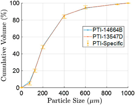
Figure 1. Particle size distributions of C-Spec test dusts (Powder Technology Inc, 2021).
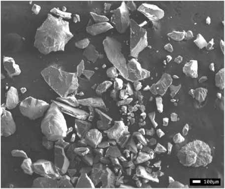
Figure 2. Particle images before engine ingestions of C-Spec test dust (Vlach et al., 2023).
Consideration is given to the efficacy of the presented method under a range of relevant flow scenarios. While the present investigation considers particle number densities, which are moderately sparse, there is no evidence to suggest that a theoretical minimum or maximum effective particle concentration exists for the data processing technique. Instead, care needs to be taken to ensure that adequate image-capturing capabilities are in place for the flow of interest. A high particle concentration corresponding to a “brown-out” condition, for example, may require decreased laser power and/or decreased exposure time to capture images on a time-dependent basis adequately. In the extreme case where the laser sheet is unable to fully penetrate the domain on a time-dependent basis, measurement uncertainty may reach excessive levels, and the method would, in fact, be ineffective. Engineering judgment should be used to evaluate the effectiveness of hardware configurations. Furthermore, for cases where particle number densities reach excessively high levels, it may be appropriate to mitigate multiple light scattering effects by data post-processing using methods such as the previously described SLIPI technique. Lastly, care should be taken to ensure individual image pixels are not saturated, particularly for the calibration case. Saturation makes the actual value of the pixel intensity indiscernible. This will result in an inaccurate calibration constant estimate and an overestimation of total particle mass flow.
3 Validation experiment
3.1 Test particles
The material of interest for these tests is MIL E-5007C, commonly known as C-Spec, a commercially available mixture of crushed quartz. This material is known for having a wide distribution of particle sizes, which is representative of dusts encountered by operational aircraft. Particle sizes of C-Spec range from roughly 50
3.2 Test facilities
All tests discussed herein have been conducted at the Virginia Tech Particle Ingestion Engine Stand using a Rolls-Royce model M250-C20B engine operating at ground idle conditions. This condition corresponds to an engine mass flow rate of 0.744 kg/s and a bulk flow velocity of 64 m/s as measured by the test cell data acquisition system. The sand is introduced into the inlet flow under two conditions: a full-loading and a half-loading. The full-loading condition results in a particle concentration of 45 mg/m3, and the half-loading condition produces a particle concentration of 22.5 mg/m3. These values are chosen based on evidence provided by Clarkson, which suggests that exposure at these levels may result in significant engine deterioration and erosive damage (Clarkson et al., 2016). Four tests are conducted, two at each loading condition, at 5-min intervals of sand exposure. A table of the testing conditions is presented in Table 1.
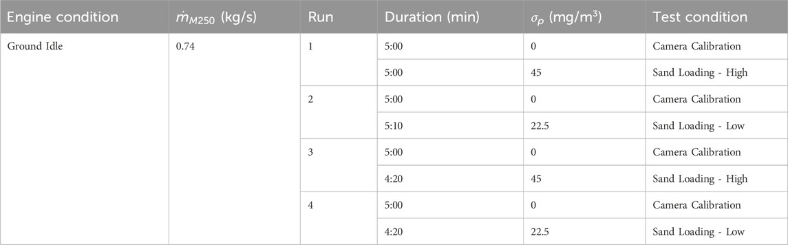
Table 1. Engine test conditions given the engine throttle condition, engine air mass flow rate (
3.2.1 Engine test stand
Researchers at Virginia Tech are interested in conducting on-engine sand exposure tests to gain a deeper understanding of how ingestion events contribute to engine performance deterioration. Consequently, the Virginia Tech Particle Ingestion Engine Test Stand has been established as pictured in Figure 3. Also pictured are auxiliary systems, such as the water brake dynamometer for power absorption, the engine oil system for adequate lubrication, and the instrumentation and data acquisition enclosures. These enclosures contain temperature and pressure monitoring equipment as well as engine control hardware. This facility is a fully functioning engine test facility located at the Advanced Propulsion and Power Laboratory (APPL) at Virginia Tech. The facility is currently configured for a Rolls-Royce model M250-C20B turboshaft engine, which produces approximately 450 horsepower when operating at full capacity. The facility also includes an adjacent user control room, which provides noise insulation as well as protection for personnel in case of emergency, an engine stand, auxiliary oil, and fuel systems, an extensive suite of data acquisition and instrumentation for remote engine control and performance evaluation, and a water brake dynamometer system for power absorption. The facility is capable of continuous engine operation at a ground idle setting and up to 1 hour at full power for the model M250-C20B.
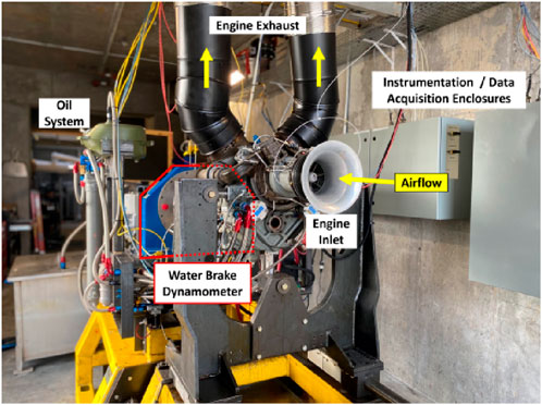
Figure 3. Virginia Tech Particle Ingestion Engine Test Stand with a Rolls-Royce M250-C20 engine installed.
3.2.2 Particle seeding
Particle seeding is achieved using an AccuRate particle feeder to provide a constant flow of C-Spec particles into the engine inlet. The feeder sits atop an Adam Equipment LTB 6002e scale, and the weight of the particle feeder is continuously monitored throughout testing. This allows for a precise measurement of total sand mass flow during each run. The feeder and scale are securely mounted to a platform above the engine inlet flow barrel. The particle feeder features a hopper filled with the sand sample and a rotating helix that transports the sand to an exit nozzle. Depending on the setting, the feeder is capable of providing sand at a feed rate from 0.2 g/min up to 2 g/min. From the exit nozzle, sand is routed into the tubing and through an Exair Line Vac pneumatic particle conveyor. This particle conveyor works by.
a. Facility compressed air is directed into an annular plenum chamber.
b. The flow is directed through nozzles into the throat of the conveyor.
c. The resulting jet creates a low-pressure region near the conveyor intake.
d. The vacuum draws particles through the conveyor and into the delivery nozzle.
The Line Vac creates a vacuum of −29.9 kPa with a supply pressure of 552 kPa. Previous investigations determined that this pressure was adequate to supply particles to the engine inlet without backflow. Particles enter the inlet flow through a delivery nozzle positioned at the centerline. The particle feeder, conveyor, and delivery nozzle are all used in conjunction to supply a consistent particle-laden flow to the engine inlet.
3.3 Measurement apparatus and procedure
A diagram of the experimental setup is shown in Figure 4. A Coherent Genesis CW laser with up to 1W output at 514.5 nm wavelength was directed to a Thorlabs Scanning Galvanometer Mirror, which induces a laser sheet at an assigned scanning frequency. The laser sheet is then truncated to a 2.54 cm strip by passing through an optical window affixed to the inlet test section. The laser sheet is projected orthogonally to the direction of flow, from the 12 o’clock position to the six o’clock position. A FLIR Blackfly S BFS-U3-31S4 camera fitted with an Edmund Optics 35 mm lens and 514.5 nm bandpass filter continuously captures images at an exposure time of 0.25 s. This camera is positioned 152.4 cm (60 in.) directly upstream of the laser sheet at an angle of 2° relative to the laser plane, as shown in Figure 4. This slight angle facilitates an unobstructed view of the inlet centerline, the primary region of interest, as shown in Figure 5. Here, a particle sampling probe used for a parallel study is positioned such that the probe opening is concentric with the cylindrical test section. We can see that the center, the region of primary interest, is clearly seen. A series of clean background images is then taken during engine operation before sand exposure. Once sand delivery begins, images are taken continuously until loading stops.
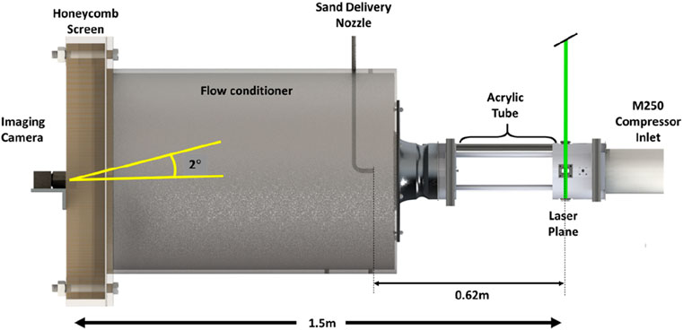
Figure 4. Experimental setup of the ParVIS technique.
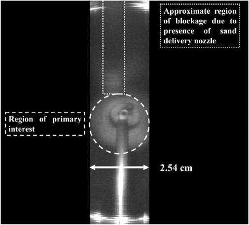
Figure 5. Image of background captured by Blackfly camera.
A background image is constructed from the mean values of a series of 240 continuous sand-free images. This composite image is then used for background subtraction. Individual sand loading images are background-subtracted to expose only sand particles passing through the laser sheet. An auto-thresholding scheme using Otsu’s method is then applied to each background-subtracted image to ensure complete isolation of sand particles (Otsu, 1979). The background-subtracted images are combined to create a single composite image that represents 1 minute of sand-loading imagery. For the experiments conducted, a series of 240 sand-loading images makes up one composite image (1 minute’s worth of data). The resulting composite image constitutes a single data series. Multiple data series images are collected for a single sand-loading campaign. Four exposure campaigns were conducted during the experiment analyzed; two at the full loading condition (45 mg/m3) and two at the half loading condition (22.5 mg/m3).
The engine inlet features a bellmouth with a flow conditioner comprising a honeycomb (3.2 mm cell, 610 mm × 610 mm, 25.4 mm thick aluminum) and two screens (0.8 mm and 0.5 mm opening sizes) on the front for flow straightening. The mass flow rate of air has been calibrated by measuring the velocity profiles across the exit of the bellmouth and the static pressures on the bellmouth. There are temperature and pressure sensors inside the flow conditioner to measure the air density. The inlet diameter is approximately 120 mm, so the laser sheet covers about 27% of the cross-sectional area. For this study, the sand is ingested along the centerline using a single nozzle. Previous investigations have determined that a 2.54 cm-wide laser sheet, centered on the inlet centerline, is sufficient to capture greater than 95% of particles under similar flow conditions with this sand delivery nozzle configuration. Therefore, the authors assume that any particles not captured by imaging constitute a statistically insignificant portion of the overall mass flow, and the reported values of the technique are comprehensive. For all results discussed, images are captured using the one-inch-wide laser strip described above and depicted in Figure 5. However, the full utility of the ParVIS technique can be realized by imaging a total cross-section of the inlet plane. Further discussion on this will be presented in Section 6 below.
4 Measurement uncertainty
An uncertainty analysis was performed to determine the precision of reported results. Overall uncertainty was calculated using a root-sum-square of individual uncertainty contributions as
where
where
5 Results and discussion
As previously stated, four exposure campaigns were conducted during the experiment analyzed: two at the full loading condition (45 mg/m3) and two at the half loading condition (22.5 mg/m3). The results of these experimental runs are presented below. We discuss both qualitative and quantitative findings. From these results, an extensive understanding of inlet particle distribution can be established. As mentioned in Section 3, the full utility of this technique is realized by imaging a comprehensive cross-section of the inlet. We intend to employ a broader approach in subsequent investigations, enabling complete cross-sectional measurements of the inlet region.
5.1 Qualitative observation
Examining the composite grayscale image in Figure 6, we can gain a broad perspective on particle behavior over 1 minute for both the high sand loading case (Figure 6A) and the low particle loading case (Figure 6B). First, it is clear that the spatial distribution of particles is non-uniform and is primarily clustered about the centerline region for both cases. As expected, there is also a higher density of particles present in the high-loading case. Lastly, there is a higher presence of particles in the bottom half of the domain than in the top half. This trend was also observed in all other data series. We confirm this observation by examining how the mean grayscale intensity values vary along the vertical direction, as shown in Figure 7. As depicted in Figure 5, a segment of the captured area was obstructed by the sand delivery nozzle located in the upper left portion of the image. Consequently, Figure 7 was generated using data from the right half of the domain exclusively. Here, we consistently observe spikes in intensity throughout the lower half of the region. Conservatively assuming particles exit the sand delivery nozzle at 10 m/s, a particle will traverse the length of the test section from the nozzle exit to the laser sheet, a distance of approximately 0.6 m, in approximately 0.06 s. Using this time (t) as a constraint, a kinematic analysis can estimate the maximum vertical drop of a given particle (dy) as
where
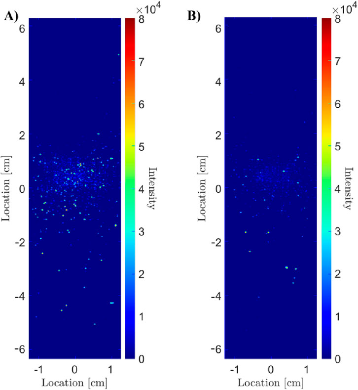
Figure 6. Composite images taken compiled for 1 minute for a high particle loading case (A) and a low particle loading case (B).
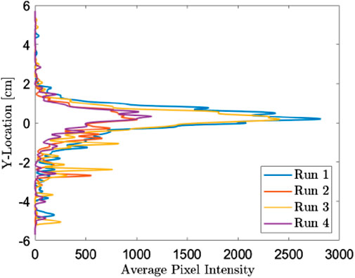
Figure 7. Average grayscale intensity values along vertical location.
5.2 Mass flow estimation
Using the data gathered for each of the data series, an average mass flow estimate is calculated for each experimental loading campaign. The accuracy of the ParVIS technique is evaluated by comparing the mass flow value predicted by the model with the known value obtained from the scale measurement, as well as the value measured by the Virginia Tech scattering-extinction particle sensor (Moon et al., 2022), as shown in Figure 8. Data is reported with error bars representing a root-mean-square deviation (RMSD) of the calculated mass flow rate. We observed that all three values are in good agreement, with a mean RMSD of 0.06 g/min or 6% (with a maximum of 8%) of the monitored value using the precision scale. The higher deviation is observed in the later run cases, which could be caused by a variation in the feed rate of the feeder from the beginning, as well as background changes due to dust deposits inside the test section. Also, not all particles may be captured by the laser sheet. Having the ability to accurately estimate the total number of particles passing through the inlet plane is a highly desirable capability for both researchers and manufacturers who are invested in reducing engine damage resulting from particulate ingestion.
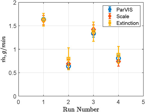
Figure 8. Mass flow estimates for the ParVIS technique (blue), the Virginia Tech Scattering-Extinction technique (yellow), and the value obtained with the precision scale (red).
As previously mentioned in Section 2.4, the variability in scattering angle resulting from the particle aspect ratio distribution of C-Spec might contribute to the uncertainty associated with the calibration constant, denoted as C. Additionally, the non-homogeneity of the test particles could also add to this uncertainty. Recent work by Vlach et al. has shown that the representative range of C-Spec particle aspect ratio varies from 1.0 ≤ AR ≤ 4.25 [47]. The influence of this increased uncertainty is evident in the error shown in Figure 8, where it is noticeable that the error exceeds the 6% uncertainty estimate from the previous analysis. This suggests that the error may be reduced by studying test dust with a narrower size and shape distribution. Strategies for mitigating this error will be the focus of future investigations.
5.3 Particle concentration
Although total mass ingested by the engine is useful for understanding life wear trends, it is typical to gauge damage trends in terms of ingested particle concentration as seen in Clarkson (2017). Using engine volumetric flow parameters, a local particle concentration map can be formed, as seen in Figure 9. Here, a pixel-binning scheme is applied to the data from Figure 6, and pixel count values are spatially averaged over the region. The width selected for this technique ensures that the region of averaging is larger than the maximum particle size being investigated. This filter enables a more straightforward interpretation of the data, allowing users to quickly identify areas of most significant particle aggregation. Figure 9 again highlights the non-uniform particle distribution within the domain, allowing us to see the local zones of greatest particle density more clearly. Figure 9A is taken from a single data series from Run 1, a run with high sand loading, and Figure 9B is compiled from a single data series from Run 2, a run with low sand loading. While the regions of greatest concentration are similar for both data sets, the concentration magnitude of the data set with the highest sand loading (Figure 9A) is more than twice that of Figure 9B, as expected. Coupling system knowledge with observations from the local particle density map presented in Figure 9, researchers can draw powerful conclusions about particle paths and particle-hardware interactions. For example, knowing the majority of particles ingested are concentrated approximately at the centerline, we can expect significant particle interaction with the inlet guide vane hub of the M250. Consequently, this will result in high rates of erosion on the hub and will also cause particles to bounce radially outward after colliding with the structure. Had this experiment been conducted using a turbofan engine instead, researchers might then conclude that the bulk of particles entered the core flow region, rather than the bypass region. This can then inform researchers about areas of greatest interest for implementing or developing wear-resistant strategies. Having a more complete depiction of the distribution of particles entering an engine is the first step to understanding how to mitigate against wear due to solid particulate ingestion.
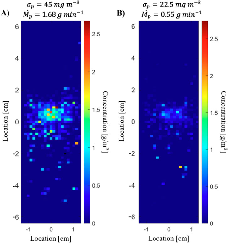
Figure 9. Local concentration from 1-min composite images.
5.4 Time-dependent data
While increasing the understanding of broad particle flow behavior is the primary goal of the ParVIS technique, there are also practical reasons for observing the data on a time-dependent basis. In Figure 10, the previously determined calibration constant is used to calculate the mass flow rate for each frame in a loading campaign for two different loading levels. These data series comprise a 5-min snapshot of the particles ingested during testing, consisting of 1,200 subsequent images taken at a 0.25-s interval. As expected, the overall magnitude of mass flow is greater for the high particle loading case. The most notable discovery, however, is that the sand delivery is not steady. Instead, we see that the loading is cyclic. This unsteadiness is due to the design of the delivery system used for this test. As discussed in Section 3.2.2, the sand delivery system used for these tests employs a rotating helix to convey sand from the hopper unit to the bulk flow. The helix rotates at a predetermined rate, which varies according to user input based on the desired test condition. Therefore, the cyclic delivery of sand particles in the frames is directly proportional to the frequency with which the helix rotates. Additionally, the magnitude of the delivery is highly variable, with large portions of the overall mass flow occurring in short bursts. These spikes in mass flow may come from an abnormally high percentage of large particles in the flow due to a heterogeneous distribution of particles within the hopper. It was confirmed that, while the peak values shown in Figure 10 are roughly two orders of magnitude higher than the reported mean mass flow values, the overall mean remains representative of the reported value. In future tests, the ability to directly interpret time-dependent data may enable shorter testing durations and lead to an extension of test engine life.
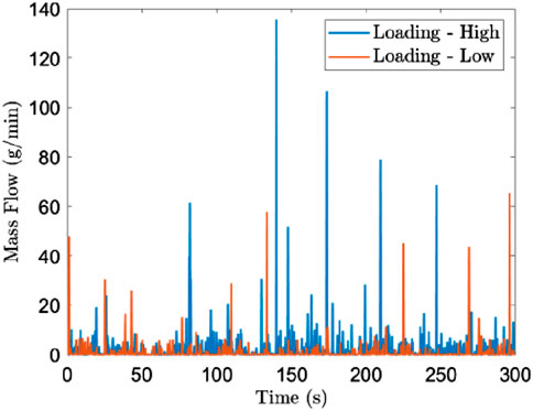
Figure 10. Time-dependent mass flow.
6 Conclusion
This work presents a framework for characterizing the particle distribution at the inlet of a gas turbine engine under conditions of particle ingestion. The method’s ability to accurately estimate the mass flow and number density of particles ingested is demonstrated on a test engine inlet at two different mass loading conditions. A known quantity of particle mass flow is supplied as an input to the method for an initial testing configuration. This known quantity is then used to calculate a calibration constant for subsequent data sets where the total mass flow rate of particulates is varied. The estimated amounts match the expected values within a reasonable uncertainty over a range of operating conditions.
The authors anticipate that the instrument’s deployment can be extended across various platforms owing to its minimal hardware requirements. This versatility allows for application across diverse engine inlet geometries and mitigates potential measurement errors resulting from engine vibrations and challenging operating conditions, distinguishing it from comparable instruments. Furthermore, the method is not confined solely to inlet sections but can be deployed in any engine region accessible through advanced fiber-optic techniques. The authors anticipate that this versatility will be of significant interest to both researchers and engine manufacturers. The primary findings from these investigations are as follows.
a. The developed technique has demonstrated effective particle mass flow and number density estimates at a range of mass loading conditions: 22.5
b. Qualitative analysis concluded that a small percentage of particles tend to bounce along the bottom of the test section. This may provide researchers with more accurate initial conditions for simulations and offer critical insights into particle flow paths.
c. Time-dependent data may inform particle flow unsteadiness.
d. Time-averaged data provides a broad perspective of particle distribution over the entire region of interest.
e. The minimal footprint of the technique, along with the relatively precise estimation of parameters of interest, makes ParVIS an attractive measurement tool when more sophisticated methods are not feasible or necessary.
As outlined earlier in Section 3.3, the full applicability of this approach hinges on its deployment across the complete cross-section. A scanning mirror and other optics can generate a wider laser sheet at the optical test section, or laser sheet-generating fibers can be installed at the front of the inlet to cover the full annulus. The experiment we present faced challenges, and it is anticipated that these challenges will intensify when attempting to deploy the technique for capturing the entire cross-section. Key difficulties involve effectively mitigating glare and combating pixel saturation resulting from particle reflection. For engine speeds higher than ground idle, two inlet conditions affect this sensor: air velocity and vibration. Increased air velocity can increase the particle velocity passing through the laser sheet, which reduces the scattered intensity. However, it can be mitigated by increasing laser power and camera exposure time. There are many anti-vibration fasteners and optics available for the presented technique. Even for field applications, it can be further developed by utilizing fiber optics and image bundles to generate a laser sheet and capture the images at the location of interest. Future research endeavors will focus on addressing these challenges and showcasing the capability in a practical, real-world context, especially within an operational engine environment. Additionally, as mentioned in Section 5.2, future work will focus on characterizing and mitigating scattering intensity errors related to particle size and aspect ratio distributions. Lastly, the presented data were gathered at the inlet of a gas turbine engine using coarse test dust, MIL E-5007C (C-Spec). Future investigations will validate the methodology using additional materials of interest, including ISO Arizona Road Dust and AFRL test dust.
Data availability statement
The original contributions presented in the study are included in the article/supplementary material, further inquiries can be directed to the corresponding author.
Author contributions
KO: Writing – original draft, Writing – review and editing. GB: Writing – original draft, Writing – review and editing. JG: Writing – original draft, Writing – review and editing. KL: Writing – original draft, Writing – review and editing. WN: Writing – original draft, Writing – review and editing.
Funding
The author(s) declare that financial support was received for the research and/or publication of this article. This work was supported by the United States Office of Naval Research under award numbers N00014-20-1-2538 and N00014-21-1-2397.
Acknowledgments
The authors would like to thank Britt Antous for her contribution to the image collection and test setup.
Conflict of interest
The authors declare that the research was conducted in the absence of any commercial or financial relationships that could be construed as a potential conflict of interest.
Generative AI statement
The author(s) declare that no Generative AI was used in the creation of this manuscript.
Any alternative text (alt text) provided alongside figures in this article has been generated by Frontiers with the support of artificial intelligence and reasonable efforts have been made to ensure accuracy, including review by the authors wherever possible. If you identify any issues, please contact us.
Publisher’s note
All claims expressed in this article are solely those of the authors and do not necessarily represent those of their affiliated organizations, or those of the publisher, the editors and the reviewers. Any product that may be evaluated in this article, or claim that may be made by its manufacturer, is not guaranteed or endorsed by the publisher.
References
Baumgardner, D., Jonsson, H., Dawson, W., O’Connor, D., and Newton, R. (2001). The cloud, aerosol and precipitation spectrometer: a new instrument for cloud investigations. Elsevier, 251–264.
Berrocal, E., Kristensson, E., Richter, M., Linne, M., and Alden, M. (2008). Application of structured illumination for multiple scattering suppression in planar laser imaging of dense sprays. Opt. express 16 (22), 17870–17881. doi:10.1364/oe.16.017870
Bird, J., and Grabe, W. (1991). Humidity effects on gas turbine performance, American Society of Mechanical Engineers. 78996.
Brun, K., Nored, M., and Kurz, R. (2012). Particle transport analysis of sand ingestion in gas turbine engines. J. Eng. Gas. Turbine. Power 134, 012402. doi:10.1115/1.4004187
Butron, D. (2020). Using SNR simulation to select a photodetector. Available online at: https://www.hamamatsu.com/eu/en/resources/webinars/detectors/using-SNR-simulation.html.
Chen, W., and Zhao, L. (2015). Review–volcanic ash and its influence on aircraft engine components. Elsevier, 795–803.
Clarkson, R. (2017). Volcanic ash and Aviation–Rolls-royce position, Available online at: [www.wmo.int].
Clarkson, R. J., Majewicz, E. J. E., and Mack, P. (2016). A re-evaluation of the 2010 quantitative understanding of the effects volcanic ash has on gas turbine engines. 230 2274–2291.doi:10.1177/0954410015623372
Dunn, M. G. (2012). Operation of gas turbine engines in an environment contaminated with volcanic ash. J. Turbomach. 134, 051001. doi:10.1115/1.4006236
Dunn, M. G., Baran, A. J., and Miatech, J. (1996). Operation of gas turbine engines in volcanic ash clouds. J. Eng. Gas. Turbine. Power 118, 724–731. doi:10.1115/1.2816987
EMVA (2025). EMVA 1288 imaging performance. Available online at: http://softwareservices.flir.com/BFS-U3-31S4-BD2/latest/EMVA/E (Accessed January 30, 2023).
Evanoff, D. D., and Chumanov, G. (2004). Size-controlled synthesis of nanoparticles. 2. Measurement of extinction, scattering, and absorption cross sections. J. Phys. Chem. B 108 (37), 13957–13962. doi:10.1021/jp0475640
Flesia, C., and Schewndimann, P. (1993). Analytical multiple scattering extension of the Mie theory, part I: general discussion. Appl. Phys. B 56, 157–163. doi:10.1007/bf00332195
Froyd, K. D., Murphy, D. M., Brock, C. A., Campuzano-Jost, P., Dibb, J. E., Jimenez, J.-L., et al. (2019). A new method to quantify mineral dust and other aerosol species from aircraft platforms using single-particle mass spectrometry. Gottingen, Germany: Copernicus Publications, 6209–6239.
Gaigalas, A., Wang, L., and Choquette, S. (2013). Measurement of scattering and absorption cross sections of microspheres for wavelengths between 240 nm and 800 nm. J. Res. Natl. Inst. Stand. Technol. 118, 1. doi:10.6028/jres.118.001
Grant, G., and Tabakoff, W. (1975). Erosion prediction in turbomachinery resulting from environmental solid particles. J. Aircr. 12 (5), 471–478. doi:10.2514/3.59826
Hamed, A., Tabakoff, W., and Wenglarz, R. (2006). Erosion and deposition in turbomachinery, 350–360.
Hanson, R. K. (1988). Combustion diagnostics: Planar imaging techniques. Symposium Int. Combust. 21, 1677–1691. doi:10.1016/s0082-0784(88)80401-6
Kim, J., Dunn, M., Baran, A., Wade, D., and Tremba, E. (1993). Deposition of volcanic materials in the hot sections of two gas turbine engines. J. Eng. Gas. Turbine. Power 115, 641–651. doi:10.1115/1.2906754
Kristensson, E., and Kristensson, G. (2017). Physical explanation of the SLIPI technique by the large scatterer approximation of the RTE. J. Quantitative Spectrosc. Radiat. Transf. 189, 112–125. doi:10.1016/j.jqsrt.2016.11.019
Kristensson, E., Berrocal, E., Richter, M., Pettersson, S.-G., and Alden, M. (2008). High-speed structured planar laser illumination for contrast improvement of two-phase flow images. Opt. Lett. 33 (23), 2752–2754. doi:10.1364/ol.33.002752
Kulkarni, A. P., Chaudhari, V. D., Bhadange, S. R., and Deshmukh, D. (2019). Planar drop-sizing and liquid volume fraction measurements of air blast spray in cross-flow using SLIPI-Based techniques. Int. J. Heat Fluid Flow 80, 108501. doi:10.1016/j.ijheatfluidflow.2019.108501
Litchford, R., Sun, F., Few, J., and Lewis, J. (1998). Optical measurement of gas turbine engine soot particle effluents. J. Eng. Gas. Turbine. Power 120, 69–76. doi:10.1115/1.2818089
Macke, A., Mishchenko, M. I., Muinonen, K., and Carlson, B. E. (1995). Scattering of light by large nonspherical particles: ray-tracing approximation versus T-matrix method. Opt. Lett. 20 (19), 1934–1936. doi:10.1364/ol.20.001934
Microtrac Camsizer X2 (2022). Microtrac Camsizer X2. Available online at: https://www.microtrac.com/products/particle-size-shapeanalysis/dynam (Accessed June 13, 2022).
Miller, E. (1996). Volcanic ash warning for pilots. 34th Aerosp. Sci. Meet. Exhib., 140. doi:10.2514/6.1996-140
Moffat, R. (1982). Contributions to the theory of single-sample uncertainty analysis. J. Fluids Eng. 104, 250–258. doi:10.1115/1.3241818
Moon, C. Y., Panda, A., Byun, G., Smith, C. F., and Lowe, K. T. (2021). Non-intrusive optical measurements of gas turbine engine inlet condensation using machine learning. Meas. Sci. Technol. 32, 044001.
Moon, C. Y., Edwards, C., Byun, G., and Lowe, K. T. (2022). “Particle characterization using optical measurements and neural networks,”. Meas. Sci. Technol. 34, 035202. doi:10.1088/1361-6501/aca423
Neal, C. A., Casadevall, T. J., Miller, T. P., Hendley II, J. W., and Stauffer, P. H. (1997). Volcanic ash-danger to aircraft in the north Pacific. U. S. Geol. Surv.
Olshefski, K., Collins, A., Coulon, T., Lowe, T., and Ng, W. (2022). Development of an anisokinetic particle sampling probe for use in a gas turbine engine compressor. Front. Mech. Eng. 8, 951986.
Otsu, N. (1979). A threshold selection method from gray-level histograms. IEEE 9 (1), 62–66. doi:10.1109/tsmc.1979.4310076
Papadopoulos, G., Bivolaru, D., and Lin, J. (2018). Real time gas turbine engine particulate ingestion sensor for particle size and composition. Turbo Expo Power Land, Sea, Air 51128 V006T05A029. doi:10.1115/gt2018-77137
Potter, J., and Tatam, R. P. (1997). Optical condensation measurement in gas turbine engine inlets. Opt. Technol. Fluid, Therm. Combust. Flow 3172, 422–2.
Powder Technology Inc (2021). Mil E-5007C material size distribution. Available online at: https://www.powdertechnologyinc.com/product/mil-e-5007/.
Rentsch, N. R. (2024). “Optical field instrumentation for characterizing particle sampling sensors, mater thesis,” in Crofton department of aerospace and ocean engineering. Virginia Tech.
Sankar, S., Maher, K., Robart, D., and Bachalo, W. (1999). Rapid characterization of fuel atomizers using an optical patternator. J. Eng. Gas. Turbine. Power 121, 409–414. doi:10.1115/1.2818488
Sorensen, C. M. (2022). Light scattering and absorption by particles: the Q-space approach. IOP Publishing.
Steiner, W. E., Klopsch, S. J., English, W. A., Clowers, B. H., and Hill, H. H. (2005). Detection of a chemical warfare agent simulant in various aerosol matrixes by ion mobility time-of-flight mass spectrometry. Anal. Chem. 77 (15), 4792–4799.
Tabakoff, W. (1984). Turbomachinery performance deterioration exposed to solid particulates environment.
Tabakoff, W. (1987). Study of single-stage axial flow compressor performance deterioration, Wear, 119, pp. 51–61. doi:10.1016/0043-1648(87)90097-4
Tabakoff, W. (1992). High temperature erosion resistance of coatings for use in gas turbine engines. Surf. coatings Technol. 52 (1), 65–79. doi:10.1016/0257-8972(92)90372-h
Tabakoff, W. (1999). Erosion resistance of superalloys and different coatings exposed to particulate flows at high temperature. Surf. Coatings Technol. 120, 542–547. doi:10.1016/s0257-8972(99)00434-x
Tabakoff, W., and Hamed, A. (1977). Aerodynamic effects on erosion in turbomachinery. Ohio: Cincinnati Univ.
Tabakoff, W., and Shanov, V. (1995). Erosion rate testing at high temperature for turbomachinery use. Surf. Coatings Technol. 76, 75–80. doi:10.1016/0257-8972(95)02507-3
Tabakoff, W., and Vittal, B. (1983). High temperature erosion study of INCO 600 metal. Wear 86 (1), 89–99. doi:10.1016/0043-1648(83)90091-1
Vlach, T., Olshefski, K., Bunin, D., Ehlers, A., Caddick, M., Lowe, T., et al. (2023). “Analysis of C-Spec particle breakage in a turbine engine particle ingestion test cell,” in Proceedings of the ASME Turbo Expo 2023: Turbomachinery Technical Conference and Exposition. doi:10.1115/gt2023-101618
Keywords: laser-imaging, particle distribution, gas turbine engine particle ingestion, local particle concentration, particle sensors
Citation: Olshefski KT, Byun G, Gillespie J, Lowe KT and Ng WF (2025) A laser imaging technique for measuring particle distribution at a gas turbine engine inlet. Front. Mech. Eng. 11:1678531. doi: 10.3389/fmech.2025.1678531
Received: 02 August 2025; Accepted: 24 September 2025;
Published: 10 October 2025.
Edited by:
Somnath De, Institute of Engineering and Management (IEM), IndiaReviewed by:
Tamonash Jana, Institute of Engineering and Management (IEM), IndiaAranyak Chakravarty, Jadavpur University, India
Copyright © 2025 Olshefski, Byun, Gillespie, Lowe and Ng. This is an open-access article distributed under the terms of the Creative Commons Attribution License (CC BY). The use, distribution or reproduction in other forums is permitted, provided the original author(s) and the copyright owner(s) are credited and that the original publication in this journal is cited, in accordance with accepted academic practice. No use, distribution or reproduction is permitted which does not comply with these terms.
*Correspondence: Gwibo Byun, Z2J5dW5AdnQuZWR1