 David B. Cameron
 Arild Waaler1
 Foivos Psarommatis
- 1Department of Informatics, SIRIUS Centre, University of Oslo, Oslo, Norway
- 2Envester AS, Oslo, Norway
- 3Aibel AS, Asker, Norway
The on-going twin transition demands that the continuous process industry builds and operates their facilities in a more sustainable way. This change affects the entire supply-chain. The market demands new ways of engineering, procuring and constructing plants that assure quality at each step of the process. Petroleum and petrochemical producers must reduce their waste and environmental footprint and find ways of migrating to sustainable production. There is zero tolerance for waste, emissions or process malfunctions. Engineering contractors need to transfer their skills to new processes and produce series, non-custom facilities for new applications like offshore wind energy, modular production and industrial symbiosis. This is leading to a convergence in methods with discrete manufacturing, especially the automotive industries. In this climate, this sector can benefit from applying Zero-defect Manufacturing (ZDM) to both engineering design and operations. This work defines a framework for implementing ZDM in the process industry supply chain. The framework brings together modelling techniques and models from the following disciplines: system engineering, computer-aided process engineering, automation (especially Industry 4.0) and semantic technologies. These contributions are synthesised into an information fabric that allows engineering firms to work in new ways. Operators and contractors can use the fabric to move from document-driven engineering to data-based processes. The fabric captures requirements and intent in design so that facilities can be delivered and started-up and operated with zero defects in the design and construction. The information is also a vital support for safe and efficient operations and maintenance. We call this zero-defect O&M. The framework combines a systems engineering break-down of facilities, based on ISO/IEC81346, with implementation in SysML, with semantic interoperability frameworks from the process industries (ISO15926). We build upon and synthesise the results of recent standardization initiatives from the industry, notably CFIHOS, DEXPI and READI. We draw on results from process systems engineering, the OntoCAPE ontology and the CAPE-OPEN standards. The framework is illustrated by application to a non-proprietary process system, namely the Tennessee-Eastman process. This example is used to show the modelling approach and indicate how the fabric supports zero-defect practices.
1 Introduction
The energy and process industries are in the throes of what the European union has called the twin transition, where industry and society is required to be sustainable and digital. Simultaneous, interlocking green and digital transformations require a reconfiguration of the types of plants we build and how we build and operate them (Digital Europe, 2021). The design and operation of sustainable plants requires a digital fabric that supports innovative, cost-effective engineering practices and ensures that zero-defect operations and maintenance (ZD-O&M) can be achieved. These imperatives mean that the process sector can benefit from adopting Zero-defect Manufacturing (ZDM) practices from the discrete manufacturing industries (Psarommatis et al., 2020a).
The process industries have always been tightly integrated energy and production systems. However, the introduction of renewable energy and circular economy is tightening this coupling. This means that engineering frameworks must be interdisciplinary, bringing together approaches and terminology from the energy and process disciplines. The adoption of Industry 4.0 technologies means that process operators have access to unprecedented amounts of information about their processes and plants. This data can be used to drive Zero-Defect Manufacturing initiatives (Psarommatis et al., 2022). However, for these initiatives to be successful, this torrent of data must be contextualized and analysed to identify and detect faults. This paper proposes a standards-based framework for contextualizing data and relating it to requirements. Our hope is that this approach will simplify implementation of ZDM in process plants.
We start with a summary statement of our objectives, methods and contribution of this paper. We follow this with a development of the framework. This starts with a review of asset information models and zero-defect manufacturing (§3.1). We discuss the concept of a cognitive digital twin (§3.2), which provides a platform for implementing our framework. The framework builds on elements of the Systems Engineering discipline. We discuss the role of requirements in ZDM and review previous work on applying Systems Engineering in the process industries (§3.3). We conclude this section with a comparison of top-down and bottom-up methods of asset modelling. Our approach is a top-down method. This then allows us to define the framework. This is then applied to a well-known example process, the Tennessee Eastman process (§4). The application shows how we can break down the process into systems and subsystems. This allows us to relate design information, requirements and constraints to these systems so that they provide a context for the using operational data to implement ZD-O&M (§4). The aim of publishing this example is to provide a realistic, open case for developing and applying semantic modelling to ZD-O&M using digital twins.
2 Summary of objectives and method
2.1 Objective
The objective of this work is to define a method of modelling that allows us to organize the design and operational data from a chemical process facility so that it can be used to support the building of cognitive digital twins and implementation of ZD-O&M. This approach provides a framework for organizing data, giving it semantic meaning and providing a foundation for building decision support and digital twin applications. This framework is needed to conquer both the volume and variety of data needed to implement digital twins. Lee et al. (2022) give typical sizes for data generated in each phase of the development of an oil platform. Conceptual design generates 100000 documents per project, detailed design generates 100000 tags, each with around 40 attributes. Construction generates a terabyte of engineering model and operation generates 3 to 4 billion data points per day. We need to divide and conquer this data. This division needs to be done along several axes. We need to be able to break complex systems into sub-systems and components. We need also to be able to consider different aspects of these systems. Our framework provides a starting point for just this type of organization of data.
The framework builds on existing standards and industry initiatives, namely ISO15926 (Leal, 2005), ISO/IEC81346 (Balslev and Barré, 2022), DEXPI (Wiedau et al., 2019), CFIHOS (IOGP JIP36, 2022) and READI (READI, 2020). The data modelling also draws on the OntoCAPE ontology for process systems (Marquardt, 2010) and the CAPE-OPEN standards (van Baten and Pons, 2014). The framework aims to integrate, reconcile and map between these standards.
The approach described here has been applied to organize process design data for an oil and gas development in the North Sea. This work is confidential. For this reason, we apply here the approach to a well-known example process, the Tennessee Eastman process (Downs and Vogel, 1993). In this way, we demonstrate the principles and applicability of the framework, while providing a resource for further research around system integration and digital twins. The SysML files for our model are available on request.
2.2 Method
The framework is built using a sub-set of the principles of model-based system engineering (MBSE). We have chosen this sub-set to bridge the conceptual divide between the MBSE and process systems engineering communities. We use SysML (Amálio et al., 2016) because of its good tool support. However we only use a limited set of SysML language features, namely blocks, ports, parameters and interfaces.
The framework consists a library of blocks, each of which represents a system with a type and aspect. These blocks are instantiated to build a model of a specific facility. The aspect of each block follows the aspect modelling approaches of OntoCAPE (Marquardt, 2010) and ISO/IEC81346 (Balslev, 2020). In our example we gave functional blocks that represent process activities and product blocks that represent the equipment needed to realize these activities.
The type of each block depends on the block aspect. A functional block is typed by the process activity that the system it represents performs. We obtain these types from the ISO/IEC81346 Reference Designation System for Oil & Gas (READI, 2020). This type is also mapped to activities in the ISO15926 reference data. A product block is typed by the type of equipment that it represents. We have chosen to use the types in the DEXPI data model (Wiedau et al., 2019) as the primary type for product blocks. Semantic references are made to ISO/IEC81346 RDS, ISO15926 and CFIHOS Tag classes. In this way we provide a practical tool for mapping and consolidating these four standards.
We can then use functional blocks to build a functional aspect model of the process and the product blocks to build a product aspect model of the plant. The resulting framework is shown in Figure 1, which is adapted from Herzog and Torne (2000).
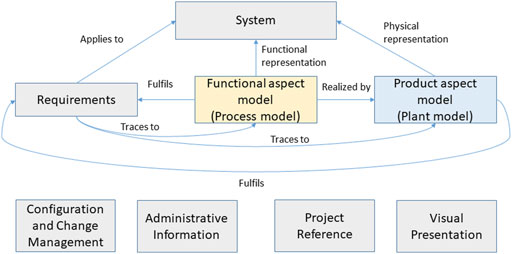
FIGURE 1. Conceptual Structure of the framework, adapted from Herzog and Torne (2000).
Each block has a common structure. It can contain parameters that define the behaviour of the block itself. It also contains one or more ports. These provide logical locations for transfer of material, energy or information between blocks. We define system topology by connecting outlet ports on one block to inlet ports on another. A connection means that the state of material, energy or information is the same in both the inlet and outlet port.
Our framework is built to support the V-process, as shown in Figure 2. Our approach builds on the insight that conceptual and front-end design defines the process model, whereas detailed engineering, procurement and construction deals primarily with the plant model. During commissioning, start-up and maintenance we are again primarily concerned with equipment, while operations and performance optimization is concerned with process aspects.
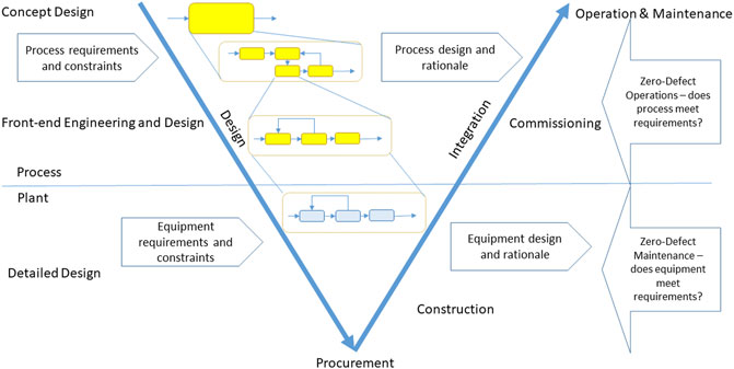
FIGURE 2. Alignment of our method with the V-process for Systems Engineering.
The modelling method can be summarised as follows.
1. Build the process model. At each level we apply the requirements and constraints that are available and relevent to that level of modelling.
a. Level 1. We start with a single functional system that represents the entire process. Ports are defined to represent flows of material, energy and information out.
b. Level 2. This system is broken down into smaller functional systems, each of which performs a specific process activity. We identify the flows of material, energy and information between these systems and model them by connecting the relevant ports in the sub-systems. At this level each sub-system represents an element in a process block diagram or process flow diagram. At this level we are interested in what is being done, for example, separation, rather than how it is being done, for example, separation by distillation.
c. Level 3. Each of these sub-systems can be broken down further into smaller functional systems. Here we are interested in what is done and how it is done, i.e., the unit operation used. Each block in this level corresponds to an element in process flow diagram.
d. Support Functions. Finally, for each sub-system in level 3, we add functional blocks that model the safety, control, maintenance and utility functions that are needed to support that unit operation. We now have all the functional models needed to specifiy the plant model. A graphical view of this model can be thought of as a functional piping and instrumentation diagram.
2. Build the plant model. Here we introduce equipment requirements, such as piping standards, to select equipment that realizes the process.
a. For each block in level 3, build a plant model that represents the equipment that realizes the unit operation and its supporting functions. Each block in this model corresponds to an element in the piping and instrumentation diagram.
b. An overall plant model is then an aggregation of the plant models defined in the previous step, with the topology defined by the process model.
In this paper we apply this method down to level 3 on the Tennessee Eastman process. We then indicate how the further steps would be done.
3 State of art and development of method: Semantic data fabrics for zero-defect manufacturing
3.1 The promise of zero-defect manufacturing
Quality is a critical aspect of manufacturing systems whether they be continuous or discrete. The term quality not only refers to product quality but also to the quality of the manufacturing facility. (Psarommatis et al. (2022); Psarommatis (2021); Psarommatis et al. (2020a)). Sustainable manufacturing, which is a key goal of the contemporary industrial landscape, requires high quality on both of these areas: process quality (which includes product quality) and plant quality (which includes design quality). Poor quality causes direct and indirect economic losses as well as environmental impact from wasted resources (material, manufacturing time and energy). To overcome these issues, companies must implement quality management tools to increase their operational performance and extend the overall sustainability of production (Kumar et al., 2018). Poor quality can also have negative social impact. For example a poor quality product could severely damage the image of a company because of the customer dissatisfaction or product contamination (Jun et al., 2020).
Traditionally, production companies implement one or more quality improvement (QI) methods to maintain and improve production quality and minimize performance loss (Özcan et al., 2021). Traditional methods are Six-Sigma (SS), lean manufacturing (LM), theory of constraints (TOC), and total quality management (TQM). They mainly focus on product quality and use statistical tools to improve quality. Recent practice has moved from statistical methods towards data-driven technologies coming from the Industry 4.0 concept. Traditional QI methods were designed using the technologies available at the time, without the knowledge of recent technological advances under the framework of Industry 4.0 (Psarommatis et al., 2020b). Methods such as artificial intelligence, machine learning or semantic modelling present new ways for manufacturers to achieve targets that would have been impossible in the past (Lindström et al., 2020).
Use of data driven technologies is also boosted by the tremendous increase in computational power and availability of cheap sensors (Mourtzis et al. (2016); Chien et al. (2013); Kuo et al. (2013); Choi et al. (2012)). These factors created a new quality management approach called Zero-defect manufacturing (ZDM) (Psarommatis et al., 2020a), which started in the discrete manufacturing domain but is applicable to continuous manufacturing. ZDM is different in that it is a holistic approach, which assesses all the different stages of the production, starting from design of the product and production to the operation of the production system (Psarommatis, 2021). The goal of ZDM is to reduce waste and increase the sustainability of manufacturing systems (Psarommatis et al., 2022).
ZDM employs four strategies: detect, predict, prevent and repair. These strategies are implemented in pairs. In total, three paired strategies can exist (Psarommatis et al., 2020a). If you detect a defect you can repair it, or try to prevent a future defect, and using the data from detected anomalies predict when defects will occur in the near future and prevent them. Maintenance lies within the scope of the ZDM concept as a way of preventing and repairing defects. For example, when there is a prediction of an equipment failure, predictive maintenance is required to maintain KPIs at desired levels (Psarommatis et al., 2021). The design of both the product and its production systems plays a significant role in achieving ZDM. Very few studies exist on how to design a manufacturing system to achieve ZDM. Psarommatis (2021) proposed a methodology that uses a digital twin to properly design a manufacturing system for using the four ZDM strategies to achieve ZDM. Semantic modelling and data and information models play key roles in determining the efficiency and capabilities of data driven technologies for ZDM (Ameri et al. (2022); Grevenitis et al. (2019)). This paper describes a fabric for building such information models.
3.2 Cognitive digital twins
The digital twin provides an implementation pattern for platforms that support implementing ZDM using Industry 4.0 methods. The twin is a digital application that allows a user to make informed decisions about the behaviour of a physical or social system by combining three things: 1) information about structure of the system with 2) measurements and observations and 3) results of simulations of the system that mirror and predict system behaviour (Cameron et al., 2018). The digital twin provides copious data about system behaviour. What is challenging is to access the data, contextualize it and make decisions based on it. The data must be supplemented with semantic information that puts data into context, brings together related data and allows automatic reasoning. A digital twin that incorporates this information is called a cognitive twin (Zheng et al., 2021). Automation of ZDM requires these cognitive capabilities to be in place.
What we present in this paper is a semantic representation of the design of a production facility so that it provides a top-down context for data, models and measurements. This context allows us to relate the data we obtain from a digital twin to the requirements that are embodied in the plant and its process. This will allow us to enrich the digital twin with cognitive functionality.
3.3 Zero-defect engineering, operations & maintenance: On-line compliance with life-cycle requirements
3.3.1 Overview of approach
Much of the cognitive functionality of a digital twin is related to answering the question of whether the current behaviour of the production system is in compliance with requirements. To do this, we need to retrieve relevant requirements effectively. Unfortunately, many of these requirements are textual or are embedded in off-line documentation. Requirements that are critical for safety and operation will have been implemented as alarm limits in the process control system. This results in a “flattening” of requirements, where we lose the context and rationale behind a specific alarm (Goel et al., 2017). A predictive maintenance program will also monitor key equipment for compliance with product requirements for parameters such as temperature and vibration.
We aim here to provide a system-based information model that allows us to record requirements during design and connect them to system objects at the highest possible level of abstraction. This allows us to use the same model during operation to organize data from a digital twin and contextualize it using the requirements captured during design. This supports reasoning, as we have access to the rationale behind monitoring and alarms in the system, thereby accessing the shared memory in the design (Konda et al., 1992). This philosophy is shown in Figure 3.
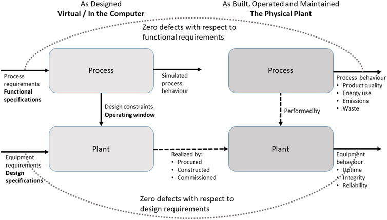
FIGURE 3. Use of process and plant models to Support ZD-O&M.
This figure shows the virtual and physical elements of a digital twin. We apply an information model during design that captures the design as a collection of functional information about the process. This is then used to design and specify the plant, the actual equipment in the facility (Bramsiepe et al., 2014). The functional model is the basis for the simulations that are used to define the design window for the plant equipment. The specified facility is then procured, constructed and commissioned. The operated plant is then responsible for executing the process. Our aim is that the information model will allow the tracking of design rationale down from initial process functional design to the functional and plant design for individual pieces of equipment. We build an information model that contains linked hierarchies of system objects that allow the tracking of design rationale in a way that supports better operations.
3.3.2 Process and plant defects
We are interested in detecting and avoiding defects in both the process and the plant. A defect in the process is a failure to meet requirements on the amount, composition or physical properties of a product, by-product, waste or emission. A defect in the plant is the failure of the equipment to meet its requirements, by, for example, failing, leaking or degrading. Plant defects can, of course, lead to process defects. A worn impeller in a pump (a plant defect) will lead to a failure to deliver a required amount of pumped product (a process defect). The converse can also happen. A failure to remove hydrogen sulphide from a stream (process defect) can lead to stress corrosion cracking in downstream piping (a plant defect). Our aim is to provide a model that allows detection of and rectification of both types of defect through alignment with our asset model that separates process and plant concerns.
Note that here we deviate from common ZDM terminology. Discrete manufacturing identifies two types of defects: in the product and in the process. Defects in the manufacturing equipment are then a type of process defect. Thus, what we call a process defect includes conventional ZDM product defects as a sub-set. What we call a plant defect corresponds to a conventional ZDM process defect. We ask the reader to bear with this inconsistency, as we believe our separation of process from plant is essential for effective data and requirement management in the process industries.
3.3.3 Reconciling systems engineering with process systems engineering
An asset model requires information objects that represent functional systems in the process model and items of equipment in the asset model. The Process Systems Engineering discipline has focused on the unit operations approach, where a plant design is broken into functional unit operations that are then realized by equipment (Cameron and Gani, 2011). Focus is on the simulation tool and modelling environment (Cameron and Ingram, 2008), with proprietary and ad hoc interfaces to design information systems (Marquardt and Nagl, 2004), where Microsoft Excel is a common integration platform (Fricke and Schöneberger, 2015).
Model-based systems engineering (MBSE) approaches have not been used widely in the process industry, despite being well established in manufacturing. This approach formalizes the design process into the creation of system models, which are progressively broken down into sub-systems. This workflow is supported by models developed using the SysML language and written using a specialized MBSE tool (Dori, 2016). The MBSE tools and the SysML language allow detailed modelling of functionality and support simulation using tools like Modelica (Amálio et al., 2016). This is well-suited for cyber-physical systems, where MBSE provides a well-integrated tool chain. However, linkages to common process simulation tools are not common, especially from MBSE tools. We have experienced that MBSE tools and methods are complex and unfamiliar to process engineers.
Hernandez et al. (2016) and Rodriguez et al. (2017) describe how a SysML model can be used to describe the function and structure of a simple chemical plant. They modelled the process using SysML activity diagrams and then transformed these into block definition diagrams. These models could then be transformed further into simulation models, piping and information diagrams and functional models for HAZOP and fault diagnosis. We discuss below on why we do not believe that activity diagrams are a good way to model the asset information.
We believe, however, that the modelling principles used by Hernandez et al. (2016) and Rodriguez et al. (2017) are useful. We prototype our model in SysML using block definition diagrams, since the model exploits standard modelling elements in SysML, but our model is not dependent on SysML. This means that we build up our model from typed blocks, where a block represents a system at an appropriate level of abstraction. These blocks contain typed ports, which define points at which systems interact through an interface. Engineering systems interact through a flow of 1) material, 2) energy, or 3) information. They can also be 4) connected structurally. Each interaction is characterized by a data structure. Thus a fluid material flow at a port is characterized by a flow rate, composition, temperature and pressure. The items in these data structures—port parameters—can be referenced by requirements. They define how a block interacts with other blocks. A block also has its own block parameters, that characterize the object or system that the block models. This block stucture is common in system thinking and resembles the IDEF0 standard (Kikuchi et al., 2012). Here we structure the inputs, outputs, controls and resources used by an IDEF0 activity into materials, energy and information flows.
The model presented here is a SysML implementation of the ideas developed in the READI Information Modelling Framework project (Fjøsna and Waaler, 2021). We describe how this works out in the next section.
3.3.4 Semantic rigour in asset information models
An asset model provides most benefits if it can be used to support interoperability and data exchange between vendors and customers. To do this, we need an agreed semantics for the systems we are using. Current SysML versions (before the forthcoming version 2.0) lack a formal semantics (Graves, 2009). An interoperable asset model requires an agreed semantics for what blocks, ports, connections and parameters represent. We try to do this by building our modelling elements so that they reference existing ontologies, taxonomies and semantic standards. Our aim is to use our model to consolidate and reconcile existing standards.
Our model is informed by the following ontologies and standards.
• We build on the concepts in the OntoCAPE ontology (Marquardt (2010); Morbach et al. (2007)). This is a comprehensive ontology for process systems engineering. It makes a clear distinction between process and plant aspects, as required for our work. It also provides a semantic framework for representing material properties.
• We obtain types of process, piping and instrumentation equipment blocks from the DEXPI (Wiedau et al., 2019) data model. This builds on OntoCAPE and also references the reference data in ISO15926 Part 4 (Leal, 2005).
• We then align the equipment block types with other standards in the ISO15926 family, especially CFIHOS (IOGP JIP36, 2022).
This gives us an ontological basis for building a library of equipment blocks that can be used to model the plant. Following OntoCAPE, these block types are specializations of a Plant Item. However, we also need to model the process. Here we find that existing ontologies and standards provide less support. They are suitable for bottom-up modelling of an asset, where have existing pieces of equipment. It is thus straightforward to use ISO15926, CFIHOS or DEXPI to identify a type of equipment, for example a CENTRIFUGAL PUMP (http://data.posccaesar.org/rdl/RDS416834). We can then define a block to represent the functional specification (what CFIHOS calls tag properties) for a centrifugal pump. We can then also create a block to represent the properties of the actual installed pump (what CFIHOS calls the equipment properties).
3.3.5 The Information modelling framework: A system approach to engineering, operations and maintenance
However, this tight linkage between function and equipment hinders the type of modelling needed to represent a process rather than a plant. Here we are interested in a top-down design, where we progressively break down a facility into the functional systems that will contain subsystems, several of which may have function of pumping. Note that a system that does the activity of pumping will usually not be a single pump. It is rather a functional object that is realized by an assembly of equipment, in this case a pump, its back-up pump, their motors, and the pipes and valves that are needed to connect the pumps to the rest of the plant, control operations and maintain safe operation.
We therefore need a semantics of systems that can be used to model the design of processes. Following the READI Information Modelling Framework (Fjøsna and Waaler, 2021), we have chosen to use the Reference Designation System (RDS) (Balslev (2020); Balslev and Barré (2022)) classification defined in ISO/IEC81346-2 RDS (IEC TC3, 2009b). This provides a hierarchical classification of systems based on “viewing each object as a means of performing an activity often with an input and output” (p8). Systems that perform multiple activities are classified according to their primary activity. The standard seems to use the terms “activity”, “intended purpose” and “task” as synonyms. This standard lacks semantic rigour, so we have sought to supplement it with system concepts from OntoCAPE.
The RDS used is the O&G RDS proposed by the READI Joint Industry project (READI, 2020) (https://readi-jip.org/reference-designation-system-for-oil-and-gas/) for oil and gas processes. This follows ISO/IEC81346-2 closely, with a set of “Oil & Gas Systems” at the top level of the classification. It then follows with a set of technical systems, which are then developed to component systems, as defined in ISO/IEC81346-2.
A different RDS has been developed in Germany for the process industry, which is standardized as DIN 6779-13:2018 (DIN-Normenausschuss Technische Grundlagen and DIN-Normenausschuss Rohrleitungen und Dampfkesselanlagen, 2018). They build a hierarchy of functional systems where a chemical complex is broken down into processes, process sections and unit operations. This corresponds to a plant breakdown into plant sections, technical equipment and components. The coding used deviates from ISO/IEC81346-2. Technical systems are designated by a single letter, whereas ISO/IEC81346-2 uses two letters. Thus, “C” designates a storage system, whereas ISO/IEC81346-2 uses “QA”, “QB” or “QC”, depending on whether gas, liquids or solids ar stored.
Component systems are designated in DIN-6779-13 by two letters, whereas ISO/IEC81346-2 uses three letters. The letters chosen are the first letters in the corresponding ISO/IEC81346-2 codes. For example, DIN-6779-13 uses “GP” to designate a system for pumping fluids, whereas ISO/IEC81346-2 uses “KE” to designate a pumping technical system and “GPB” to designate a centrifugal pumping component system. Work is underway to provide semantic mappings between the ISO/IEC81346-2 RDS and the DIN 6779-13 RDS.
Aspects are a vital part of our modelling approach. ISO/IEC81346 (IEC TC3 (2009a); Balslev (2020)) defines three aspects for any object or system:
• what an object is intended to do or what it actually does: the function aspect. Objects in this aspect are coded with an equals (=) sign.
• the means by which an object does what it is intended to do: the product aspect. Objects in this aspect are coded with a minus (−) sign.
• the intended or actual space occupied by the object: the location aspect. Objects in this aspect are coded with a plus (+) sign.
This approach is also adopted by OntoCAPE, which defines the concept of aspect systems. A chemical process system is broken down into process unit objects, which are then modelled by different but linked aspect systems (Marquardt (2010),p244), as shown in Figure 4.
• A process system to model the function aspect. This is built up of process step objects, each of which represents the function of a process unit.
• A plant system to model the realization aspect. This is built up of plant item objects, each of the which represents the realization of the process unit, i.e. the actual equipment used.
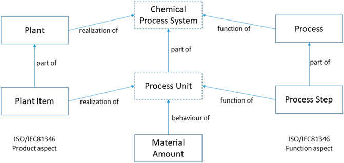
FIGURE 4. Aspect models in OntoCAPE.
Note that the function and realization aspects in OntoCAPE correspond to the function and product aspects in ISO/IEC81346. Note also that the Chemical Process System and Process Unit objects are not explicitly used in the framework.
3.3.6 Modelling material properties
OntoCAPE uses the concept of a material amount, as shown in Figure 4, to represent the behaviour of a process unit. This behaviour aspect model is essential for Zero Defect O&M, as manufacturing processes in the process industries have a primary function of producing materials with a specified composition and thermodynamic state. Quality of product consists of achieving and maintaining these specifications.
This means that a behaviour model, an interoperable representation of material properties and chemical thermodynamics, is needed in any system model of a processing plant. Here we use a model based on OntoCAPE and the CAPE-OPEN standard for interoperability of simulation (van Baten and Pons, 2014). A Material object can be associated with any port with a material interface. It corresponds to the material amount concept in OntoCAPE. The Material object contains the state of the material at this point: temperature, pressure, composition and flow rate. If a material consists of several phases, the material object can reference one or more Phase objects. These contain the composition and flow rates of each phase. The structure of Material and Phase objects is described by a Material Template object. This framework allows us to link requirements on composition, purity, flow, temperature and pressure to any port in an asset model. It also simplifies data transfer to and from common process simulation tools, as it reproduces the CAPE-OPEN data model.
3.3.7 Linkage to design work-flows and artefacts
We can summarize the presentation of our framework by linking it to the process design work-flows and artefacts. Figure 5 shows how our model works. Design of a new chemical plant or oil field begins with functional design, where large systems are proposed to fulfil the requirements expressed in the design basis. These design choices are documented in a facility or field block diagram. Each of these large blocks is then broken down into the technical systems needed to meet these requirements. This breakdown is documented in a Process Block Diagram. Each technical system is then broken down into component systems, as can be shown on a Process Flow Diagram. Each block at this level corresponds to specific unit operation, where we have a clear idea as to the equipment needed to realize this function. However, every piece of main equipment in a plant needs a set of supporting functions (for example, monitoring, controlling, relieving, draining and isolating) to be implemented if it is to be run and maintained properly. We therefore extend our functional modelling to include these functions. This can be documented on a new type of diagram, that we call an Intelligent PFD.
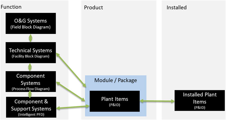
FIGURE 5. Summary of the framework for process design.
All this modelling uses functional system blocks and is in the function aspect. All our design is based on applying functional requirements to the process to obtain the design window for the equipment in the plant. We are now able to realize this functional model by building a corresponding model in the product aspect. This provides the plant items (functional specifications of equipment) that are shown in a Piping & Instrumentation diagram, 3D model and equipment list. We can then link this model further to an object in the installed aspect that contains information about the actual installed piece of equipment.
This approach is best explicated by considering a specific example. Here we present and discuss a functional model of a well-known benchmark problem: the Tennessee Eastman Process.
4 Application to the Tennessee Eastman process
4.1 Description of the process
The Tennessee Eastman process is a chemical process that was published for use a research benchmark for plant-wide control design (Downs and Vogel, 1993). In the two decades since it was published, it has been used by many workers as a basis for work on plant control (Lyman and Georgakis (1995); Rodriguez and Marcos (2002); Vinson et al. (1995)), optimization (Jha and Okorafor (2014); Jockenhövel et al. (2003)), simulation (Cameron and Gani (2011); Martin-Villalba et al. (2018)), monitoring (Chen et al. (2014); Jiang and Yan (2015); Lau et al. (2013)), education (Udugama et al., 2020) and generation of synthetic datasets (Andersen et al. (2020); Capaci et al. (2019)). We will use the process to demonstrate how our system modelling can be used to structure design decisions and information about the process. We also use the process to validate the applicability of our RDS system blocks.
There are eight chemical species in the system: four reactants (A,C,D and E), two products (G and H), a by-product (F) and an inert substance (B). The reactions that can occur are as follows:
The process flow diagram is shown in Figure 6. It shows a process that consists of a stirred, cooled chemical reactor. Exothermic reactions here produce a vapour product that is partially condensed. The liquid and vapour are then separated in a drum. The vapour is then compressed and recycled to the reactor, with a purge stream used to control the level of impurities (B and F).
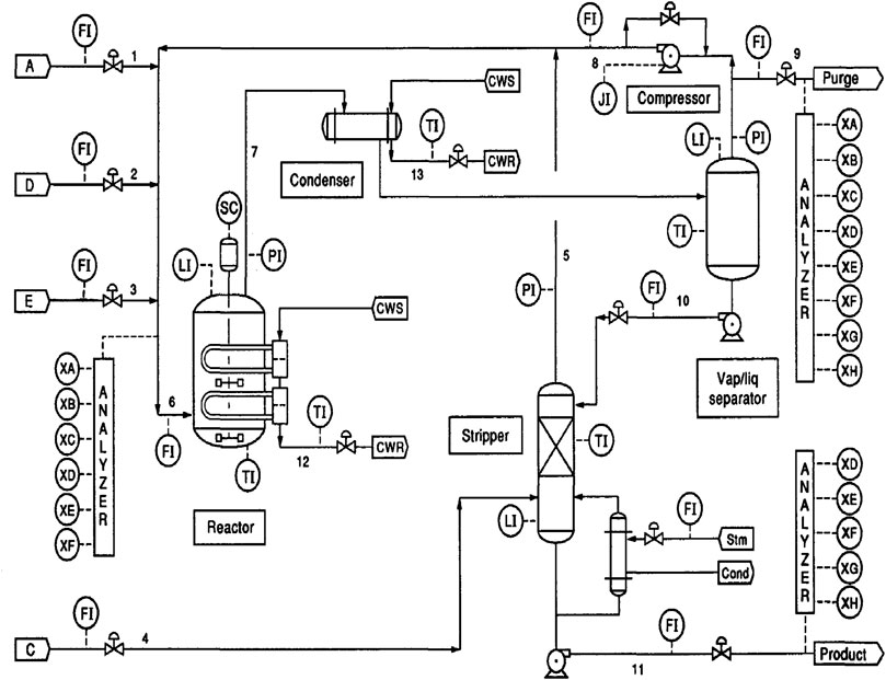
FIGURE 6. The Tennessee eastman process, from Downs and Vogel (1993).
The liquid from the separator is pumped as reflux to a stripper column, which is fed with component C. The bottoms from this column form the product stream (G and H), while the vapour from the stripper is recycled to the reactor, as it contains reactants.
Cao et al. (2021) applied an ontology-based modelling framework to this process. They used a very simple ontology based around the concept of a procedure, that is related to 1) an operation, with in and out flows, 2) materials, raw materials and products and 3) performance indicators (cost, environmental impact, energy, carbon and safety). This allowed them to produce a knowledge graph that represented the unit operations and material flows in the process. They then proposed that this graph could be used for fault analysis and reasoning. Our model is semantically richer, but we envisage that graph models like this could work together with our framework to solve specific ZDM problems.
4.2 Modelling the process
4.2.1 Level 1: The process block
We model the process in three steps. We first represent the entire process by a single system. The primary function of this system is to convert A, C, D and E into G and H. We therefore use a = D Processing System block to represent the overall behaviour of the plant. This block has four material inlet ports (XL1 [0] to XL1 [3]), two material outlet ports (XL2 [0] and XL2 [1]), and an electrical energy port (XD1 [0]) that can be used to model the plant’s power consumption. This block is shown as the frame in the top-level process block diagram shown in Figure 7.

FIGURE 7. The top-level model of the Tennessee eastman process.
4.2.2 Defining material properties
We need to structure the material properties in the system. We do this by defining a Material Template object that provides the template for specified and calculated Material objects at ports and inside blocks. The Material Template refers to eight Chemical Component objects, one for each of the components A to H. The Chemical Component object can store pure component properties for each species.
4.2.3 Level 2: Top-level modelling: Process block diagram
The plant is then broken down into functional systems, as shown in Figure 7. Here we code the systems with two-letter, technical system codes from ISO/IEC81346-2 and the O&G RDS. We are interested here in what is done, not how it is done. We therefore decompose system D1 into the following sub-systems:
• A =KL Chemical Reaction system, =KL1.
• Two =KC Separation systems, =KC1 and =KC2.
• A =KJ Thermal Exchange system, =KJ1.
• A =KK Compression system. =KK1.
Each of these represents what DIN 6779-13 calls a process section (Verfahrensabschnitt).
We can then connect ports to build the flow topology of the process. Here a connection means that the ports connected coincide and have the same state. We also connect ports in which material enters or leaves the process to corresponding ports in the parent system. We do this for the feeds, the purge and the product stream.
We also draw cooling water and steam from utility systems. It is likely that these are part of some site infrastructure. We can represent them in the design by two =JA Fluid Transportation systems, =JA1 and =JA2.
4.2.4 Activities or functional blocks?
We could choose, like Hernandez et al. (2016), to model the system function with an activity diagram. This is shown in Figure 8. Here we see that there is a one-to-one mapping between activities and functional blocks. The topology is also the same, and we could associate Material objects with the flows between activities. However, we do not recommend using activity diagrams for this analysis. SysML activity diagrams are designed for detailed modelling of system behaviour, not the high-level functions shown here. They are also redundant. All information in an activity diagram is mirrored in the block definition diagrams. Use of block definition diagrams also enables us to use consistent modelling at all levels of the asset model. However, it is useful to retain activities as they provide a link between our functional systems and the ISO15926 family of semantic models.
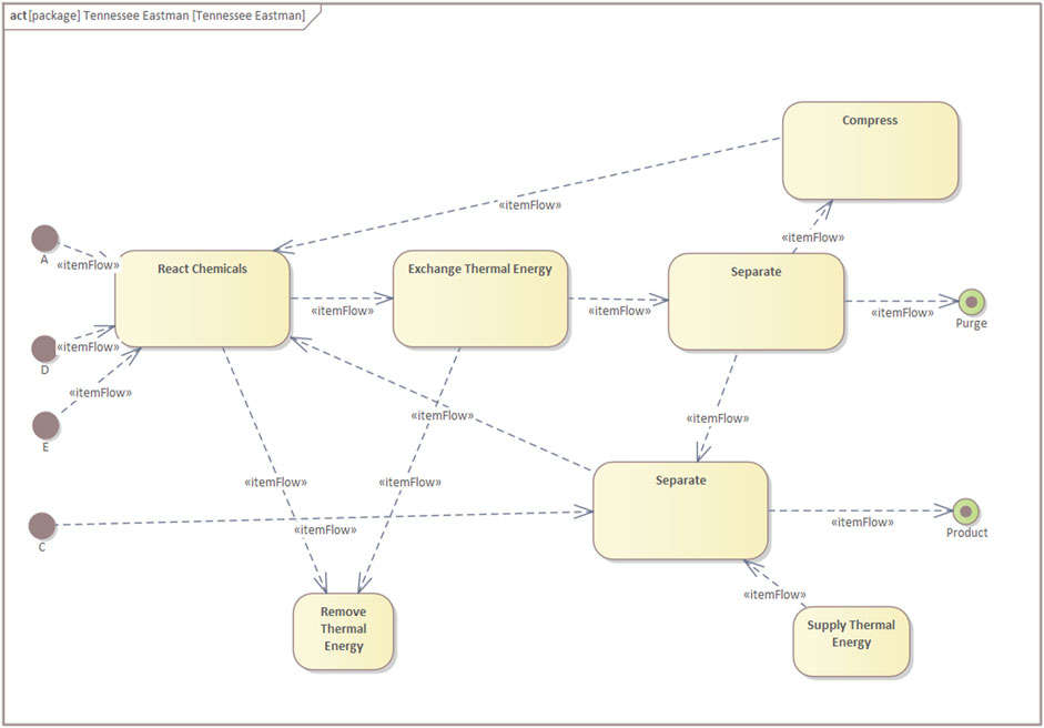
FIGURE 8. The top-level activity model of the Tennessee eastman process.
4.2.5 Level 3: Middle-level modelling: Process flow diagram
We can now look at each technical system in turn and ask how the desired functionality is to be achieved. The results of these analyses are recorded in the Process Flow Diagrams for each process section. Here we define the component systems that are required to provide the function of each process section. A component system specifies both what is done and how it is done. It corresponds to a unit operation (Grundoperation) in DIN 6779-13.
We have done this for all the process sections above. The results are shown in Figures 9–13 for the reaction, compression, thermal exchange and two separation systems respectively.
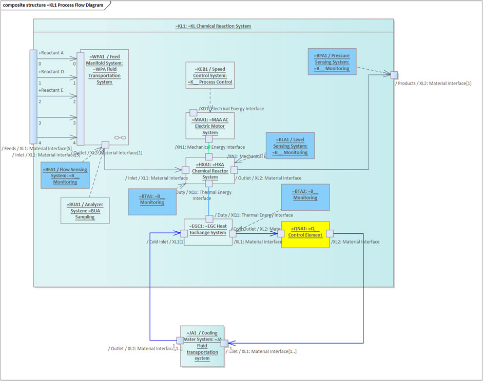
FIGURE 9. The second-level model of the chemical reaction system.
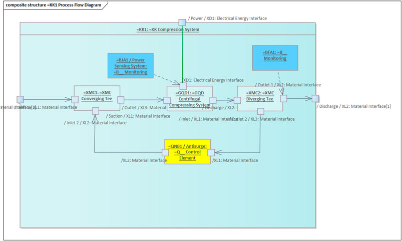
FIGURE 10. The second-level model of the compression system.
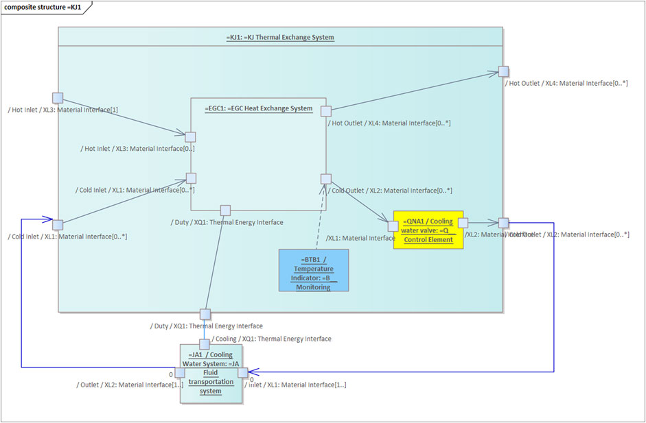
FIGURE 11. The second-level model of the heat exchange (condenser) system.
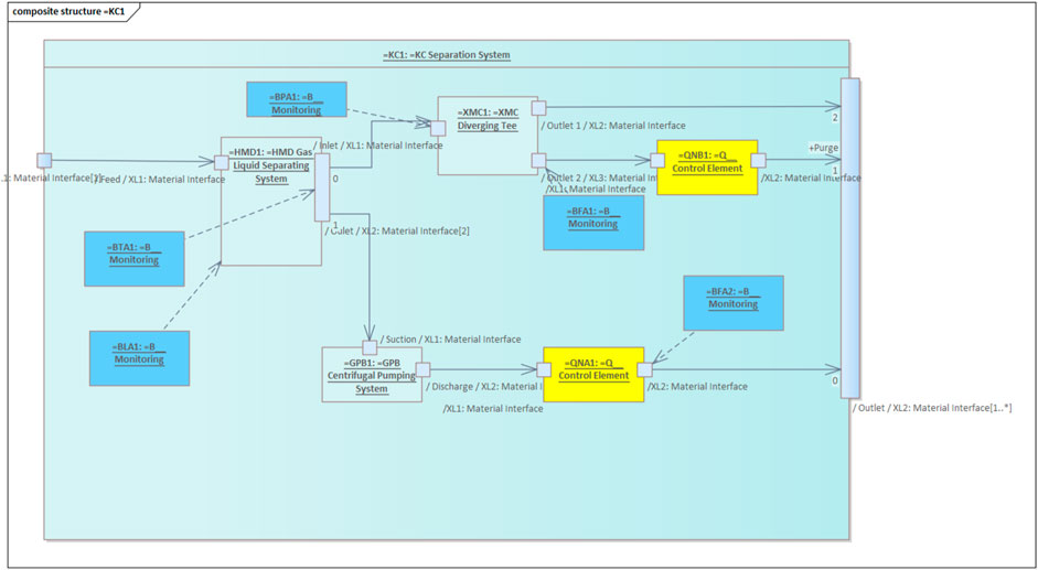
FIGURE 12. The second-level model of the separating (gas-liquid separating) system.
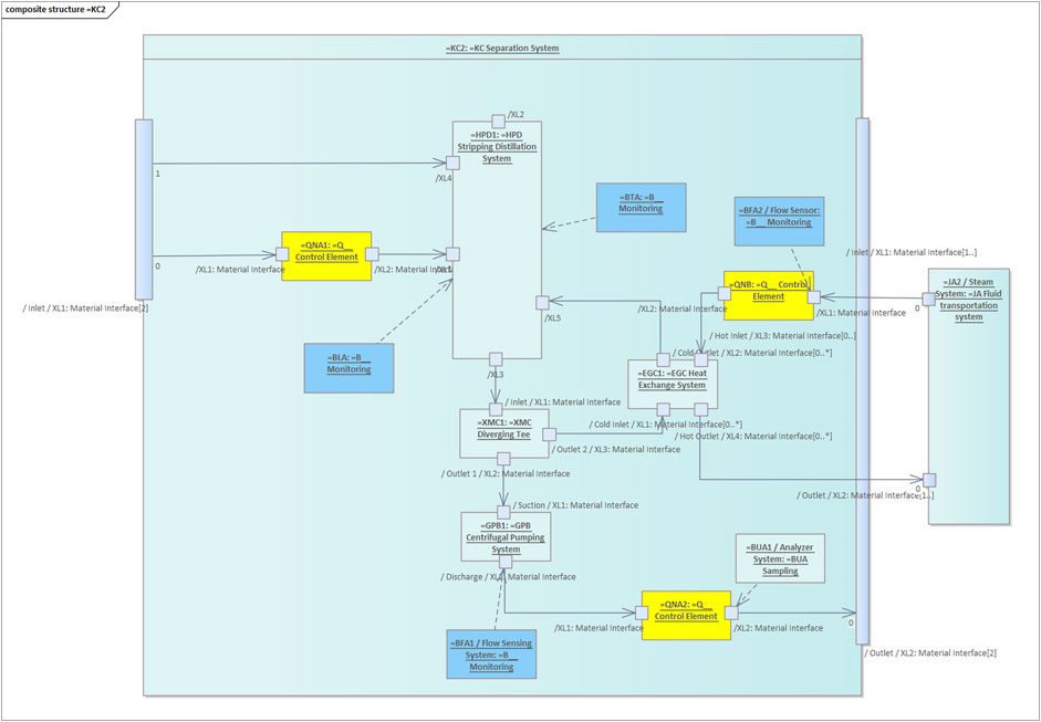
FIGURE 13. The second-level model of the separating (stripping distillation) system.
In a process flow diagram systems are represented by symbols that resemble the equipment that will realize the main function of the system. We are thus also interested in the flow topology between these symbols. We need to be able to represent divergence and convergence of connecting flows. This is done by defining two functional systems: an =XMC Diverging Tee and an =XMC Converging Tee.
We also need to define the controlled variables and manipulated variables for overall process control. We will need a =B__ Monitoring system for each controlled variable and a =Q__ Control Element system for each manipulated variable. These are examples of the type of supporting systems we need to make the process safe and operable.
4.2.6 Lower-level modelling: Supporting functions and transfer to the product aspect
We would then continue the decomposition of each component system into a further diagram where we specifiy the supporting functions that are needed to run, maintain and operate the system. For example, consider the chemical reactor. It must be protected from high temperature, low level, high level, low pressure and high pressure. This means we need to introduce monitoring and protection (PSV) functions. We need to be able to isolate the vessel for cleaning and maintenance. We must be able to prevent reverse flow into the vessel. We must be able to drain the vessel. We also need supporting functionality that is provided by equipment internals and fixtures. For example, heating will require a heating coil or tube bundle. Demisting will require a cyclone or a demister pad.
Each of these functions is realized by specifying and installing equipment on the plant. This equipment is shown on the piping and instrumentation diagram and can be represented by a block in the product aspect. We can move from the function aspect to the product aspect by:
1. Specifying the equipment needed to realize the main function of the component system. For our chemical reactor this is a pressure vessel with a heating coil and an agitator.
2. Specifying the equipment that is needed to convey material, energy and power to and from the main equipment.
3. Specifying the equipment needed to implement each supporting function.
The specification of equipment is done using engineering standards and a design window of flow, pressure, temperature and composition, that is generated by the functional design. Using this approach we can relate every piece of equipment in the plant to some functional system. This allows us to trace the design choices for each piece of equipment back to the functional requirements of the system of which they are a realization. This allows us to identify common requirements at the highest possible level and maintain consistency in equipment choice.
5 Building a ZD-O&M model for the Tennessee Eastman Process
5.1 Introduction
In this section we demonstrate how we link design requirements to the functional model so that it captures design intent and provides a framework for ZD-O&M. This is done using the original description of the Tennessee Eastman process in Downs and Vogel (1993). They provide a textual description of the process, its objectives and constraints. Here we work through the paper, showing how we link this information to the asset model. We also use the design rationales described in Udugama et al. (2020). We work downwards through the model, identifying relevant requirements and constraints at each level. Requirements and constraints at the higher level are inherited as we move down the hierarchy of systems.
5.2 Modelling at the top level: Design facts and high-level requirements
5.2.1 Design facts
At the top level, we have a priori information about the process. We call this information design facts, although, in practice, they may be only assumptions or estimates. These can be modelled as constraints on parameters in the ports or blocks in the model.
• The process handles eight chemicals: four reactants, two products, an inert and a by-product.
• The stoichiometric matrix for the reactions Eq. 1 to 4 is known.
• The kinetics of each reaction is known.
• A liquid phase catalyst is needed for the reaction.
• Knowledge about the upstream supply of feed materials, with maximum available flows for each stream. Disturbances in three of the feed streams will create disturbances in upstream processes. The third stream (component E) has upstream storage.
• The chemical composition, pressure and temperature of each of the feed materials.
5.2.2 Design requirements
We then look at the overall process and impose the following design requirements:
• A purge stream is needed to avoid build-up of inert and by-product.
• We want to produce three different product mixes: 50/50, 10/90 and 90/10 mass ratios of product G to product H.
• Purity constraints on the product, percentage of by-product F in product stream.
• Variability of flow rate of product must be kept within ±5%
• Variability of composition of G in product must be kept within ±5 mol%.
These constraints and requirements are shown in Figure 14. We can then perform mass balance simulations around the entire system to calculate nominal and maximum flows for all feeds and products with the three product mixes, subject to the known limits on the feed flows. We associate these values with the model as constraints, associated with different design cases. These values provide an operating window for designing the process at the middle level.
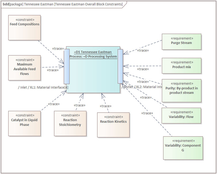
FIGURE 14. Top-level constraints and requirements.
5.3 Modelling at the middle level: Constraints and operating windows
5.3.1 Context
We now have a set of overall constraints on the plant, and can now focus on the sub-systems needed to achieve this reaction and separation. This breakdown is shown in Figure 7. In a green-field design we may consider several different possible arrangements of these unit operations. We now need to impose new functional requirements and constraints on each of these unit operations. For reasons of space, we present this process for only one sub-system, the reaction system.
5.3.2 The reaction system at the technical system level: What we need to do
Udugama et al. (2020) give a summary of the functional requirements for the reaction system:
“The objective of the reactor is to convert the feed components A, C, D and E into the products G and H. Component F is produced in the reactor as a result of side reactions and represents a yield loss. The temperature and the pressure of the reactor are critical process safety variables which need to be well controlled. The reaction is homogeneously catalysed, whereas the non-volatile catalyst remains dissolved in the liquid that is retained in the reactor. From a process control point of view, controlling the pressure, temperature and the liquid level in the reactor are important as all these variables have a direct influence on product generation and separation.”
At this stage of the design, the concept of level of liquid in the reactor is rather a material hold-up or residence time, as we have not yet sized the reactor vessel.
We can reformulate this text description as a set of refined functional requirements and constraints. This requires process calculations and steady-state simulation of the system. Here we derive detailed requirements from the broader requirements at the higher level.
• Requirements on product mix, purity and variability of G generate requirements for the reactor:
• Residence time in reactor must be sufficient to achieve desired production, purity and product mix.
• Temperature in the reactor must be controlled to achieve desired production, purity and product mix.
• Pressure in the reactor must be controlled to achieve desired production, purity and product mix.
• The reactions are exothermic, heat is generated. This means that:
• The system must be protected from high temperatures.
• The system must be protected from high pressures.
• The system will need to be externally cooled.
We now use these requirements to calculate constraints and operating windows for the following system parameters:
• Temperature - design and maximum.
• Pressure - design and maximum.
• External cooling duty (a constraint on port XQ1).
This is shown in Figure 15.
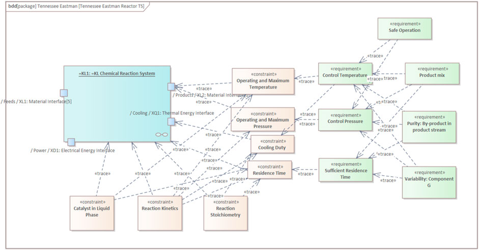
FIGURE 15. Technical-system-level constraints and requirements.
5.3.3 The reaction system at the component system level: What we need to do and how to do it
We see from the above analysis that we need provide the following component systems to conduct the process defined above. This requires us to make some choices about the unit operations to be used and we need to think about the how the functionality will be delivered. We make the following choices:
• The reaction component system will be a continuous stirred tank system.
• This means that we will need a motor system to drive the agitator in the reactor.
• Cooling will be provided by a heat exchange system.
The constraints and requirements from the higher level transform into constraints and requirements on each component:
• Cooling duty gives rise to the following constraints:
• Area of heat exchanger.
• Cooling water flow.
• Speed of agitator.
• Power of motor.
• The residence time gives rise to
• Size of the stirred-tank system.
• Operating, maximum and minimum level.
Constraints on controlling temperature and pressure follow on from the higher-level model.
5.3.4 Realizing the systems
At this stage we have identified systems that correspond to the main processing equipment. We then need to add supporting functionality, such as shut-down and pressure relief valves. Once this is done we can apply design standards to specify the reactor size, shape and shell thickness, the agitator design, the motor model and the heat exchanger bundle type and size. This is the sort of information that is maintained in conventional engineering information systems and links to maintenance and asset management systems. What we have shown above is a framework that tracks the rationale behind the performance constraints that we will use in a Zero-Defect operation and maintenance program.
6 Conclusions and perspectives
This paper has described and given a practical example of a top-down functional system breakdown of a complex production facility. We believe that this approach provides a valuable way to capture, share and reuse design rationale to ensure that we have zero defects in the process plants we build and operate. To be scalable, sharable and interoperable, the model must have a defined and standards-based set of semantics. We have not presented the semantic technologies used to support this, as our focus has been on the content and domain example that needs to be represented in the model.
We are currently working on linking semantic models, expressed as ontologies, to the SysML model described here. Once this is done, we will be able to provide unambiguous semantics for each block and parameter in the model. This will allow automated reasoning about the model and its contents. Such reasoning can be used in engineering to check the consistency of design decisions and verify that purchased and installed equipment meets requirements. In operations and maintenance we can link design rationale to each individual quality metric. This supports diagnostic reasoning and could enable autonomous operation.
The reader will note that we have not used semantic languages such as OWL 2 and RDF in this paper. This is deliberate, as our focus here is on developing a framework for using systems concepts to organize our process and plant data. The choice of technology is secondary to the model. We believe that the framework will consist of three, interacting data stores, as shown in Figure 16.
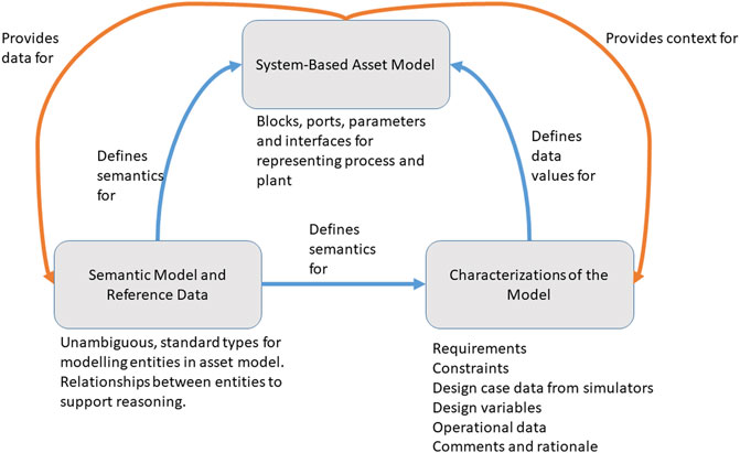
FIGURE 16. A possible architecture for our framework.
Adopting a system engineering modelling approach offers us the opportunity to examine how comprehensive frameworks such as MSDISE, Model-driven Interoperability for Systems Engineering (Zacharewicz et al., 2020) can be translated from the manufacturing domain to the process industries. Our modelling framework reflects only a small part of the modelling domain described there. We believe, however, that our model can capture the core data needed to design, validate and operate process facilities. This system-oriented structuring of design information also offers a context for linking requirements that are represented as computable statements rather than text (Lebeaupin and Rauzy, 2020).
The system-based asset model is a collection of instances of objects, such as SysML blocks, with ports, parameters and interface definitions. We assign a type to the entities in this model using a semantic model and reference data, implemented using semantic technologies. This model refers to the asset model and can be used to check correctness of the asset model and reason about content in the asset model. Both of these models represent structure of the data. Neither the asset model nor the semantic model are suitable for storing the design data itself, the characterizations of the model, in a scalable way. In design and operation there will be many data sets that refer to a specific parameter in an asset model. For example, the discharge pressure for a pump will be referred to by:
• A design constraint for normal operating pressure.
• A safety constraint for maximum design pressure.
• Calculated values from a number of design cases.
• Real-time data from the plant’s monitoring system.
Our ambition is to use the asset model to contextualize this data in the systems in which it is best stored and manipulated. This requires interoperability and mapping between the data stores for the characterizations. The semantic model provides this, while the asset model gives the context for each data item.
There is a pressing need for research, standard development and implementation to bring this vision to reality. This paper provides a practical example that can stimulate thought, validate semantic models and facilitate adoption of systems thinking in data management for process engineering.
Data availability statement
The raw data supporting the conclusions of this article will be made available by the authors, without undue reservation.
Author contributions
DBC was the main author and FP contributed the material on zero-defect manufacturing. AW, EF and MH have developed the IMF modelling concept and its application to the process industry.
Funding
This work was partially funded by the Research Council of Norway through the SIRIUS Centre for Research-Based Innovation, project 237898 and the PeTWIN project 294600. It was also supported partially by the following EU H2020 project: Eur3ka (101016175).
Acknowledgments
The authors wish to acknowledge the companies in the READI Joint Industry Project for their support in developing the IMF and the O&G RDS. This work also draws on the experience of applying these approaches to modelling the NOAKA field development, which is a collaboration between Equinor, Aibel, Aker Solutions and AkerBP.
Conflict of interest
The authors declare that the research was conducted in the absence of any commercial or financial relationships that could be construed as a potential conflict of interest.
Publisher’s note
All claims expressed in this article are solely those of the authors and do not necessarily represent those of their affiliated organizations, or those of the publisher, the editors and the reviewers. Any product that may be evaluated in this article, or claim that may be made by its manufacturer, is not guaranteed or endorsed by the publisher.
References
Amálio, N., Cavalcante, A., Miyazawa, A., Payne, R., and Woodcock, J. (2016). “Foundations of the SysML profile for CPS modelling,” in Tech. Rep. (Aalborg: D2.2a, INTO-CPS Project).
Ameri, F., Sormaz, D., Psarommatis, F., and Kiritsis, D. (2022). Industrial ontologies for interoperability in agile and resilient manufacturing. Int. J. Prod. Res. 60, 420–441. doi:10.1080/00207543.2021.1987553
Andersen, E. B., Udugama, I. A., Gernaey, K. V., Bayer, C., and Kulahci, M. (2020). Big data generation for time dependent processes: The Tennessee eastman process for generating large quantities of process data. Comput. Aided Chem. Eng. 48, 1309–1314. doi:10.1016/B978-0-12-823377-1.50219-6
Balslev, H. (2020). A guide to RDS - reference designation systems. TAG numbers for systems in accordance with the ISO/IEC81346 standard series. No. 166 in DS handbooks. 3rd edn. Copenhagen: Danish Standards Foundation.
Balslev, H., and Barré, T. (2022). “Why system models need the RDS 81346 reference model,” in Proceedings 32nd Annual INCOSE Symposium, Detroit, MI, 18.
Bramsiepe, C., Krasberg, N., Fleischer, C., Hohmann, L., Kockmann, N., and Schembecker, G. (2014). Information technologies for innovative process and plant design. Chem. Ing. Tech. 86, 966–981. doi:10.1002/cite.201400029
Cameron, D. B., Waaler, A., and Komulainen, T. M. (2018). “Oil and Gas digital twins after twenty years. How can they be made sustainable, maintainable and useful?” in Proceedings of The 59th Conference on Simulation and Modelling (SIMS 59), 26-28 September 2018 (Oslo, Norway: Oslo Metropolitan University), 9–16. Linköping University Electronic Press, Linköpings universitet.
Cameron, I. T., and Gani, R. (2011). Product and process modelling: A case study approach. 1st ed. Amsterdam ; Boston: Elsevier. OCLC: ocn749857547.
Cameron, I. T., and Ingram, G. D. (2008). A survey of industrial process modelling across the product and process lifecycle. Comput. Chem. Eng. 32, 420–438. doi:10.1016/j.compchemeng.2007.02.015
Cao, J., He, Y., and Zhu, Q. (2021). An ontology-based procedure knowledge framework for the process industry. Can. J. Chem. Eng. 99, 530–542. doi:10.1002/cjce.23873
Capaci, F., Vanhatalo, E., Kulahci, M., and Bergquist, B. (2019). The revised Tennessee Eastman process simulator as testbed for SPC and DoE methods. Qual. Eng. 31, 212–229. doi:10.1080/08982112.2018.1461905
Chen, H., Tiňo, P., and Yao, X. (2014). Cognitive fault diagnosis in Tennessee Eastman Process using learning in the model space. Comput. Chem. Eng. 67, 33–42. doi:10.1016/j.compchemeng.2014.03.015
Chien, C.-F., Hsu, S.-C., and Chen, Y.-J. (2013). A system for online detection and classification of wafer bin map defect patterns for manufacturing intelligence. Int. J. Prod. Res. 51, 2324–2338. doi:10.1080/00207543.2012.737943
Choi, G., Kim, S.-H., Ha, C., and Bae, S. J. (2012). Multi-step ART1 algorithm for recognition of defect patterns on semiconductor wafers. Int. J. Prod. Res. 50, 3274–3287. doi:10.1080/00207543.2011.574502
Digital Europe (2021). “Digital action: 8 ideas to accelerate the twin transition,” in Tech. rep. (Brussels, Belgium: Digital Europe).
DIN-Normenausschuss Technische Grundlagen (NATG) and DIN-Normenausschuss Rohrleitungen und Dampfkesselanlagen (NARD) (2018). DIN 6779-13 Kennzeichnungssystematik für technische Produkte und technische Produktdokumentation – teil 13: Chemieanlagen. Berlin: Deutsche Norm, DIN Deutsches Institut für Normung e. V.
Dori, D. (2016). Model-based systems engineering with OPM and SysML. New York, NY: Springer New York. doi:10.1007/978-1-4939-3295-5
Downs, J., and Vogel, E. (1993). A plant-wide industrial process control problem. Comput. Chem. Eng. 17, 245–255. doi:10.1016/0098-1354(93)80018-i
Fjøsna, E., and Waaler, A. (2021). “READI information modelling framework (IMF). Asset information modelling framework,” in Tech. rep. (Oslo: READI Joint Industry Project).
Fricke, A., and Schöneberger, J. (2015). Industrie 4.0 with MS-excel? Chem. Eng. Trans. 43, 1303–1308. doi:10.3303/CET1543218
Goel, P., Datta, A., and Mannan, M. S. (2017). Industrial alarm systems: Challenges and opportunities. J. Loss Prev. Process Industries 50, 23–36. doi:10.1016/j.jlp.2017.09.001
Graves, H. (2009). “Integrating SysML and OWL,” in Owl: Experiences and directions 2009 (OWLED 2009) (Kyiv, Ukraine: CEUR-WS), Vol. 529.
Grevenitis, K., Psarommatis, F., Reina, A., Xu, W., Tourkogiorgis, I., Milenkovic, J., et al. (2019). A hybrid framework for industrial data storage and exploitation. Procedia CIRP 81, 892–897. doi:10.1016/j.procir.2019.03.221
Hernandez, C., Rodriguez, M., Diaz, I., and Sanz, R. (2016). “Model based engineering of process plants using SysML,” in Computer aided chemical engineering. Vol. 38 of 26 European symposium on computer aided process engineering. Editors Z. Kravanja, and M. Bogataj (Amsterdam, Netherlands: Elsevier), 1281–1286. doi:10.1016/B978-0-444-63428-3.50218-6
Herzog, E., and Torne, A. (2000). “Support for representation of functional behaviour specifications in AP-233,” in Proceedings seventh IEEE international conference and workshop on the engineering of computer based systems (ECBS 2000) (Edinburgh, UK: IEEE Comput. Soc), 351–358. doi:10.1109/ECBS.2000.839895
IEC TC3 (2009a). IEC 81346-1 Industrial systems, installations and equipment and industrial products - structuring principles and reference designations - Part 1 Basic rules. Geneva: International Standard IEC 81346-1 Ed. 1, IEC.
IEC TC3 (2009b). IEC81346-2 Industrial systems, installations and equipment and industrial products - structuring principles and reference designations - Part 2: Classification of objects and codes for classes. Geneva: International Standard, IEC.
Jha, A., and Okorafor, O. C. (2014). Optimal plantwide process control applied to the Tennessee eastman problem. Ind. Eng. Chem. Res. 53, 738–751. doi:10.1021/ie402215d
Jiang, Q., and Yan, X. (2015). Nonlinear plant-wide process monitoring using MI-spectral clustering and Bayesian inference-based multiblock KPCA. J. Process Control 32, 38–50. doi:10.1016/j.jprocont.2015.04.014
Jockenhövel, T., Biegler, L. T., and Wächter, A. (2003). Dynamic optimization of the Tennessee Eastman process using the OptControlCentre. Comput. Chem. Eng. 27, 1513–1531. doi:10.1016/S0098-1354(03)00113-3
Jun, J.-h., Chang, T.-W., and Jun, S. (2020). Quality prediction and yield improvement in process manufacturing based on data analytics. Processes 8, 1068. doi:10.3390/pr8091068
Kikuchi, Y., Papadokonstantakis, S., Banimostafa, A., Sugiyama, H., Hungerbühler, K., and Hirao, M. (2012). “Analysis and modeling of information required for process assessment on environment, health, and safety by IDEF0 and UML,” in Computer aided chemical engineering. Vol. 31 of 11 international symposium on process systems engineering. Editors I. A. Karimi, and R. Srinivasan (Amsterdam, Netherlands: Elsevier), 1392–1396. doi:10.1016/B978-0-444-59506-5.50109-7
Konda, S., Monarch, I., Sargent, P., and Subrahmanian, E. (1992). Shared memory in design: A unifying theme for research and practice. Res. Eng. Des. 4, 23–42. doi:10.1007/BF02032390
Kumar, P., Maiti, J., and Gunasekaran, A. (2018). Impact of quality management systems on firm performance. Int. J. Qual. Reliab. Manag. 35, 1034–1059. doi:10.1108/IJQRM-02-2017-0030
Kuo, C.-F., Hsu, C.-T. M., Fang, C.-H., Chao, S.-M., and Lin, Y.-D. (2013). Automatic defect inspection system of colour filters using Taguchi-based neural network. Int. J. Prod. Res. 51, 1464–1476. doi:10.1080/00207543.2012.695877
Lau, C., Ghosh, K., Hussain, M., and Che Hassan, C. (2013). Fault diagnosis of Tennessee Eastman process with multi-scale PCA and ANFIS. Chemom. Intelligent Laboratory Syst. 120, 1–14. doi:10.1016/j.chemolab.2012.10.005
Leal, D. (2005). ISO 15926 ”Life Cycle data for process plant”: An overview. Oil Gas Sci. Technol. -. Rev. IFP. 60, 629–637. doi:10.2516/ogst:2005045
Lebeaupin, B., and Rauzy, A. (2020). Toward a better integration of requirements and model-based specifications. Syst. Eng. 23, 751–769. doi:10.1002/sys.21560
Lee, J., Cameron, I., and Hassall, M. (2022). Information needs and challenges in future process safety. Digit. Chem. Eng. 3, 100017. doi:10.1016/j.dche.2022.100017
Lindström, J., Kyösti, P., Lejon, E., Birk, W., Andersson, A., Borg, M., et al. (2020). Zero defect manufacturing in an industry 4.0 context: A case study of requirements for change and desired effects. SSRN J. doi:10.2139/ssrn.3717709
Lyman, P. R., and Georgakis, C. (1995). Plant-wide control of the Tennessee Eastman problem. Comput. Chem. Eng. 19, 321–331. doi:10.1016/0098-1354(94)00057-U
Marquardt W (Editor) (2010). OntoCAPE: A re-usable ontology for chemical process engineering. RWTH edition (Heidelberg, New York: Springer).
Marquardt, W., and Nagl, M. (2004). Workflow and information centered support of design processes—The IMPROVE perspective. Comput. Chem. Eng. 29, 65–82. doi:10.1016/j.compchemeng.2004.07.018
Martin-Villalba, C., Urquia, A., and Shao, G. (2018). Implementations of the Tennessee eastman process in Modelica. IFAC-PapersOnLine 51, 619–624. doi:10.1016/j.ifacol.2018.03.105
Morbach, J., Yang, A., and Marquardt, W. (2007). OntoCAPE—a large-scale ontology for chemical process engineering. Eng. Appl. Artif. Intell. 20, 147–161. doi:10.1016/j.engappai.2006.06.010
Mourtzis, D., Vlachou, E., and Milas, N. (2016). Industrial big data as a result of IoT adoption in manufacturing. Procedia CIRP 55, 290–295. doi:10.1016/j.procir.2016.07.038
Özcan, A. M., Akdoğan, A., and Durakbasa, N. M. (2021). “Improvements in manufacturing processes by measurement and evaluation studies according to the quality management system standard in automotive industry,” in Digital conversion on the way to industry 4.0. Editors N. M. Durakbasa, and M. G. Gençyılmaz (Cham: Springer International Publishing), 483–492. doi:10.1007/978-3-030-62784-3_41
Psarommatis, F. (2021). A generic methodology and a digital twin for zero defect manufacturing (ZDM) performance mapping towards design for ZDM. J. Manuf. Syst. 59, 507–521. doi:10.1016/j.jmsy.2021.03.021
Psarommatis, F., May, G., Dreyfus, P.-A., and Kiritsis, D. (2020a). Zero defect manufacturing: State-of-the-art review, shortcomings and future directions in research. Int. J. Prod. Res. 58, 1–17. doi:10.1080/00207543.2019.1605228
Psarommatis, F., May, G., and Kiritsis, D. (2021). Predictive maintenance key control parameters for achieving efficient Zero Defect Manufacturing. Procedia CIRP 104, 80–84. doi:10.1016/j.procir.2021.11.014
Psarommatis, F., Prouvost, S., May, G., and Kiritsis, D. (2020b). Product quality improvement policies in industry 4.0: Characteristics, enabling factors, barriers, and evolution toward zero defect manufacturing. Front. Comput. Sci. 2. doi:10.3389/fcomp.2020.00026
Psarommatis, F., Sousa, J., Mendonça, J. P., and Kiritsis, D. (2022). Zero-defect manufacturing the approach for higher manufacturing sustainability in the era of industry 4.0: A position paper. Int. J. Prod. Res. 60, 73–91. doi:10.1080/00207543.2021.1987551
Rodriguez, M., Díaz, I., Bermejo, J., Sanz, R., and Hernández, C. (2017). “Integral management of process plants systems through their lifecycle using a model-based engineering approach,” in Computer aided chemical engineering. Vol. 40 of 27 European symposium on computer aided process engineering. Editors A. Espuña, M. Graells, and L. Puigjaner (Amsterdam, Netherlands: Elsevier), 2035–2040. doi:10.1016/B978-0-444-63965-3.50341-X
Rodriguez, M., and Marcos, A. (2002). Plantwide control design using an expert system. IFAC Proc. Vol. 35, 157–161. doi:10.3182/20020721-6-ES-1901.01494
Udugama, I. A., Gernaey, K. V., Taube, M. A., and Bayer, C. (2020). A novel use for an old problem: The Tennessee Eastman challenge process as an activating teaching tool. Educ. Chem. Eng. 30, 20–31. doi:10.1016/j.ece.2019.09.002
van Baten, J., and Pons, M. (2014). CAPE-OPEN: Interoperability in industrial flowsheet simulation software. Chem. Ing. Tech. 86, 1052–1064. doi:10.1002/cite.201400009
Vinson, D., Georgakis, C., and Fossy, J. (1995). “Studies in plant-wide controllability using the Tennessee Eastman Challenge problem, the case for multivariable control,” in Proceedings of 1995 American Control Conference - ACC’95 11, 250–254. doi:10.1109/ACC.1995.529247
Wiedau, M., von Wedel, L., Temmen, H., Welke, R., and Papakonstantinou, N. (2019). ENPRO data integration: Extending DEXPI towards the asset lifecycle. Chem. Ing. Tech. 91, 240–255. doi:10.1002/cite.201800112
Zacharewicz, G., Daclin, N., Doumeingts, G., and Haidar, H. (2020). Model driven interoperability for system engineering. Modelling 1, 94–121. doi:10.3390/modelling1020007
Keywords: semantic technologies, systems engineering, zero-defect manufacturing, requirements, ontologies, industry 4.0, interoperability, knowledge representation
Citation: Cameron DB, Waaler A, Fjøsna E, Hole M and Psarommatis F (2022) A semantic systems engineering framework for zero-defect engineering and operations in the continuous process industries. Front. Manuf. Technol. 2:945717. doi: 10.3389/fmtec.2022.945717
Received: 16 May 2022; Accepted: 23 August 2022;
Published: 21 September 2022.
Edited by:
Maria Holgado, University of Sussex, United KingdomReviewed by:
Greg Zacharewicz, Institut Mines -Télécom Mines Alès, FranceElisa Negri, Politecnico di Milano, Italy
Copyright © 2022 Cameron, Waaler, Fjøsna, Hole and Psarommatis. This is an open-access article distributed under the terms of the Creative Commons Attribution License (CC BY). The use, distribution or reproduction in other forums is permitted, provided the original author(s) and the copyright owner(s) are credited and that the original publication in this journal is cited, in accordance with accepted academic practice. No use, distribution or reproduction is permitted which does not comply with these terms.
*Correspondence: David B. Cameron, ZGF2aWRiY0B1aW8ubm8=