 Chunlin Yan
 Wei Liu
 Hongwei Yuan
- 1CETC Advanced Mobile Communication Innovation Center, Shanghai, China
- 2The 50th Research Institute of China Electronics Technology Group Corporation, Shanghai, China
Massive machine type communications (mMTC) are one of the critical requirements for beyond fifth generation (B5G) communication systems. Services for a huge number of user terminals should be provided simultaneously due to the explosive development of mMTC. It is proved that non-orthogonal multiple access (NOMA) is effective in satisfying such a requirement. In this paper we evaluate the impacts of numerous factors, such as channel encoding, channel decoding, repetition number, multi-user detector, and number of receiver antennas, on the performance of NOMA. It is surprised to find that some conclusions drawn from orthogonal multiple access system may do not hold anymore for NOMA systems. The factors which have significant impact on the performance of NOMA should be paid more attention to in the system design. The analysis and evaluation results shine more light on how to design an effect NOMA scheme by considering both transmitter and receiver to fulfill the requirements of mMTC for B5G systems.
1 Introduction
Wireless communication greatly enrich people’s work and life. The main target of third generation wireless communication and fourth generation (4G) wireless communication systems is communication for human beings. Thus a high transmission data rate is the main pursing goal; 4G communication systems offer data rates up to 100 Mbps while it is 10 Gbps for fifth generation (5G) communication systems. To avoid interference in 4G wireless communication systems, orthogonal multiple access (OMA) is applied. A large bandwidth is divided into multiple non-overlapped sub-bands, and each user occupies one sub-band. By using orthogonal resource allocation in multiple access, multi-user interference is avoided.
Due to the quickly developing internet of things (IoT), there are significant requirements for huge user terminal connections. For example, in 5G wireless communication systems, 1,000,000 simultaneous connections per square mile is the requirement, which is ten times the 100,000 units per square mile of 4G. To meet the requirement of massive user terminal connections, non-orthogonal multiple access (NOMA) was proposed (Dai et al., 2015; 3GPP, 2018b). As the IoT develops, more terminal connections should be provided in the future. NOMA is essential to achieve this goal.
In a previous study, NOMA was evaluated by a multiple access signature. Interleaver, scrambling, spreading code, modulations, and sparse mapping can be applied as a multiple access signature. Different NOMA schemes, such as interleaver-division multiple access (IDMA), sparse code multiple access (SCMA), multi-user shared access (MUSA), pattern-division multiple access (PDMA), and resource spread multiple access (RSMA) were proposed and evaluated (Liang et al., 2018; R1-1808049, 2018; R1-1801416, 2018; R1-1608755, 2016; R1-164688, 2016). Because in 5G low density parity check code (LDPC) is defined as the channel encoding scheme for data channel and convolutional code (CC) is excluded from 5G, LDPC is considered as the channel coding scheme in NOMA 5G. CC is seldom considered as the channel coding scheme in NOMA, although it may have advantage in terms of performance. In the performance evaluations some companies only consider maximum logarithmic maximum a posterior (max-log-MAP) decoder (NOMA, 2015; Yan, 2015). The performance gap between max-log-MAP decoder and logarithmic maximum a posterior (log-MAP) decoder is small. While there is significant performance gap for NOMA with iterative receiver between these two channel decoders, as what will be disclosed in this paper.
In this paper we evaluate the impacts of channel encoding, channel decoding, and many other factors on the performance of NOMA. It is surprised that some conclusions drawn from OMA may do not hold anymore for NOMA case. We analysis the reasons which lead to the different conclusions. The study in this paper will be helpful and useful for NOMA transmitter and receiver system designs. Because NOMA with iterative receiver has better performance than that of non-iterative receiver, in this paper we use iterative receiver for NOMA detection (R1-1808054, 2018)
NOMA is composed of several key components. Many factors can affect its performance. Channel coding is an important component of NOMA. In 5G systems LDPC is defined as the channel coding for data channel (3GPP, 2017). In 802.16e, CC is applied as channel coding for data channel and in 4G systems CC is employed as channel coding for control channel (3GPP, 2005, 3GPP, 2012, 3GPP, 2009). CC achieves excellent performance for small code length (Elias, 1955). For the services of IoT, the code length is moderate. In this case LDPC may be superior to CC for low bit error rate (BER) regions. While in moderate BER regions, CC may have better performance than that of LDPC. For OMA systems, when LDPC is superior to CC in low SNR regions, we think LDPC is preferred. While such a conclusion is invalid for NOMA systems when iterative detection is applied. For iterative detection, moderate BER regions may be more important than that of low BER regions, we will verify this conclusion in the performance evaluation section.
The channel decoding type affects the performance of channel coding scheme, thus it also has an impact on the performance of NOMA. The main LDPC decoding schemes are log-MAP decoder and max-log-MAP decoder. It is well known that the log-MAP decoder has larger implementation complexity compared with the max-log-MAP decoder. On an additive white Gaussian noise (AWGN) channel, the former has only about a 0.3
In NOMA, spreading or bit repetition are employed to suppress multi-user interference. By using bit repetition, the rate of the channel coding will increase when the same spectrum efficiency is assumed, thus we may lose the channel coding gain for a large number of bit repetitions. However, by increasing the number of bit repetitions, a large number of user equipment (UE) can be serviced simultaneously for mMTC. In B5G systems to provide services to a large number of UE may be more important. In this paper, we show the effect of repetition number on the performance of NOMA and the effectiveness of repetition number on accommodating a large number of UE.
Multi-user detection are employed in NOMA to combine the same user’s signals on different receiver antennas. Maximum ratio combining (MRC) and minimum mean square error (MMSE) are two different multi-user detection schemes. MRC does not need matrix inversion, thus it has low implementation complexity. However, its capability of multi-user interference suppression is not good enough. On the contrary, MMSE operation can effectively suppress multi-user interference at the cost of high computational complexity. In this paper, we show the performance of MRC and MMSE for NOMA. According to the evaluation results we can choose the appropriate multi-user detection scheme to fulfill the system requirements.
The number of receiver antennas is an important design parameter for NOMA. By using a large number of receiver antennas, the capability of multi-user interference suppression can be enhanced significantly. And the required SNR to achieve a satisfied quality of services is reduced greatly, which means the transmitter power can be reduced drastically for NOMA. In mMTC, it is prevailing that transmitter power is reduced because it means long battery life can be provided. We evaluate the number of receiver antennas and show its great impact on the performance of NOMA.
The paper is organized as follows. In Section 2, the NOMA transmission scheme and system model is elaborated. In Section 3, factors affecting the performance of the NOMA system are analyzed. Performance evaluations are offered in Section 4. The conclusions are provided in Section 5.
Notation: Matrices are set in boldface capital letters, vectors in boldface lowercase letters. The superscripts
2 NOMA Transmission Scheme and System Model
In 5G and B5G wireless communication systems, mMTC is becoming more and more prevalent. NOMA is effective at supporting massive user or equipment connections. Various NOMA schemes were proposed in 3rd generation partnership project (3GPP) where spreading code, codebook, bit to symbol mapping, power, interleaver, and scrambling code were used individually or jointly as user signatures (R1-1803615, 2018; R1-1808975, 2018; R1-1808968, 2018; R1-1807073, 2018; R1-164688, 2016; R1-1608755, 2016; Yuan et al., 2016; R1-1801416, 2018; Yan et al., 2016; R1-1808049, 2018; Wu et al., 2015; R1-1803665, 2018; Wu et al., 2017; R1-1612574, 2016).
A general NOMA transmission scheme is illustrated in Figure 1 (3GPP, 2018b). The information bits are encoded by channel coding. Then a bit-level interleaver or scrambling is applied. The interleaver can be a legacy one or UE-specific. A legacy interleaver means that the interleaver defined in the 3GPP of 4G is employed where the same interleaver is applied for all users. For a UE-specific interleaver, each user uses a different interleaver. The bits are then modulated. A legacy modulation or modified modulator is applied. A legacy modulator uses the same bits in the symbol mapping rules defined in 4G, and a modified modulator uses new bits in the symbol mapping rules in the modulation. UE-specific symbol-level spreading is applied to the modulated signal. The purpose of using spreading code is to reduce multi-user interference to facilitate multi-user signal detection. Resource mapping is employed to the spreading signals. UE-specific sparse mapping can be applied in the resource mapping. Multi-user interference can be reduced by using sparse mapping since only partial users’ signals instead of whole users’ signals are superposed together.
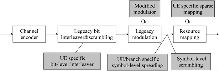
FIGURE 1. General NOMA transmission scheme (3GPP, 2018b).
In this paper, we use IDMA as the NOMA scheme, thus a UE-specific interleaver is applied. Before the interleaver is applied, bit-level repetition can be used after channel coding to reduce multi-user interference. A legacy modulation can be used for simplicity, while a modified modulator can also be applied to obtain a high data rate (Yan and Yuan, 2019). In this paper, we use legacy modulation for simplicity. After modulation, the signals are mapped on the resource.
The NOMA received signal is given by
Multiple receiver antennas are employed at the receiver side. We can use MRC at the receiver side to combine the received signals from different receiver antennas. In this case, no matrix inversion is needed, thus the computational complexity is small. However, the capability of multi-user interference suppression of MRC is weak. While the capability of multi-user interference suppression of MMSE is significantly stronger. By using MMSE operation, multi-user interference can be reduced drastically.
3 Factors Affecting Performance of NOMA Systems
NOMA is composed of several important components which have an impact on its performance, including transmitter side channel encoding, the number of bit repetitions, receiver side decoding type of channel coding. We will elaborate them one by one in the following subsections.
3.1 Types of Channel Encoding
CC was invented in the mid-1950s (Elias, 1955). After that it was applied in many systems, such as the global system for mobile communications (GSM), universal mobile telecommunications system (UMTS), and worldwide interoperability for microwave access (Wimax) 802.16e (3GPP, 2005, 2012, 2001). It has superior performance when the code length is only several hundreds, such as 60 to 300. It is excluded in 5G due to the invention of Polar code which has better performance than that of CC. However, hard output is usually provided by Polar code decoders. The complexity is high for Polar with a soft input and soft output (SISO) decoder. In NOMA, iterative detection is employed where SISO is an inherent requirement for channel coding. CC supports the SISO decoder by choosing an appropriate decoder, such as an a posteriori probability (APP) BCJR decoder or modified Viterbi decoder (Bahl et al., 1974; Hagenauer and Hoeher, 1989). The advantage of CC is its excellent balance between bit error rate performance and computational complexity. CC can be used as channel coding scheme for NOMA.
LDPC was approved as a channel coding scheme for mMTC’s data channel in 5G (3GPP, 2018a). By using the belief propagation (BP) algorithm, LDPC can achieve perfect performance. BP is one kind of SISO decoder, thus it can be used in iterative detection for NOMA. LDPC can achieve perfect performance for long code lengths. For example, when the code length is
CC can use a BCJR decoder which achieves “symbol-by-symbol” maximum a posteriori probability. SISO is supported by the BCJR algorithm. For LDPC, iterative decoding is applied where the SISO decoder is employed. For moderate code lengths, LDPC may be superior to CC in low BER regions. While in NOMA, the most interesting part of the BER curve are the moderate BER regions which correspond to low SNR regions. In NOMA, when multi-user interference is large, the signal-to-interference-plus-noise ratio (SINR) for the detected user is low. For channel coding, when it has superior performance in small SNR regions, it is preferred by NOMA. The criteria of NOMA for “better” channel encoding is different from that of OMA. Channel coding has better performance in moderate BER regions is preferred by NOMA, which is verified in Section 4. Channel coding, which has better performance in low BER regions while has worse performance in moderate BER regions, is not preferred by NOMA will be corroborated in Section 4, too.
3.2 Types of Channel Decoding
In log-MAP decoding, multiple exponential operations are needed, which means high computational complexity. To reduce the complexity, max-log-MAP can be employed. The operation for max-log-MAP is given by
The exponential operations are replaced by the operation of finding the maximal value in the M values. Thus the computational complexity is reduced significantly.
In a single user case, max-log-MAP is always employed due to its low complexity. For a multi-user with non-iterative detection scheme, the max-log-MAP decoder is also popularly used due to its small computational complexity. However, in NOMA, when iterative detection is applied there is significant performance loss using a max-log-MAP decoder. The reason is that the small difference between the log-MAP decoder and max-log-MAP decoder will be greatly amplified in the procedures of iterative detection. For mMTC, it is important to provide services to a large number of UE, thus in this case, the log-MAP decoder is preferred. The computational complexity of the log-MAP decoder can be significantly reduced by using a linear log-MAP decoder without performance loss (Valenti and Sun, 2001).
In Table 1, the different impacts of channel encoding and channel decoding on the performance of OMA and NOMA are shown. It is found the impacts are totally different for OMA and NOMA. The criterion of channel encoding and channel decoding obtained from the OMA system are not hold anymore for NOMA. We should revisit channel encoding and channel decoding for NOMA in B5G systems.

TABLE 1. Factors impacting performance of OMA and NOMA.
3.3 Multi-User Detection Scheme: Maximum Ratio Combining Elementary Signal Estimator vs. Minimum Mean Square Error ESE
To achieve the full potential of performance, iterative detection and decoding is applied for NOMA systems. ESE was proposed for the detection and decoding of IDMA (Ping, 2005; Ping et al., 2006). When multiple receiver antennas are assumed, MRC is employed for receiver signals combining. However, MRC only maximizes the power of the useful signals. The power of interference plus noise is not effectively reduced by MRC. Defining SINR as power of useful signal over power of interference plus noise, MRC cannot effectively improve SINR. Thus when interference is large, the performance of MRC ESE is much worse than that of MMSE ESE since the later maximizes the SINR, which will be shown in Section 4. In the following, we will describe the MRC ESE algorithm and MMSE ESE algorithm for single input multiple output NOMA systems, respectively.
By using MRC for the kth user we obtain
And the variance
The MRC ESE algorithm is shown in Algorithm 1. There is no matrix inversion operation, thus its implementation complexity is very low. In the following,
In Liang et al, (2018), an MMSE ESE detector was proposed. In the following, we summarize the MMSE ESE algorithm to make it more easily understood. For simplicity, the index j is omitted and (Equation 1) is rewritten as
where
Algorithm 1: Maximum Ratio Combining ESE Detector
Initialization:
for
begin
for
begin
for
begin
end
To update
To update
end
end
Output Information bits of different users (14)
Algorithm 2: MMSE ESE Detector
Initialization:
for
begin
for
begin
for
begin
end
To update
To update
end
end
Output Information bits of different users. (25)
An algorithm description for the MMSE ESE 17 detector is shown in Algorithm 2 with QPSK modulation employed.
The a posteriori mean for
A channel decoder plays an important role in the MMSE ESE detector. After using the channel decoder, more reliable soft information is achieved, which is applied in the MMSE operation and greatly improves the quality of signal detection. The higher quality of signal detection leads to more reliable soft information. When more reliable soft information is inputted into the channel decoder, higher quality output is obtained. After the predefined number of iterative detection is reached, the algorithm halts and the information bits of each user are obtained.
3.4 Repetition Number
Spreading is applied in some NOMA schemes to suppress multi-user interference. When the spreading code is applied, the symbol is spread over several resources. At the receiver side, MMSE operation is applied for multi-user suppression. The disadvantage of spreading based NOMA schemes is the high computational complexity of matrix inversion operation needed in MMSE-based iterative detection. The dimension of the channel matrix is linear with the length of the spreading code. The larger the spreading code, the better effect of the multi-user interference suppression we have, however, the larger of computational complexity we pay.
In IDMA, bit-level repetition is employed. The same bit is spread to several bits. The bits are interleaved then modulated. At the receiver side, a signal is detected. After the log likelihood ratio of each bit is obtained, the values of the repeated bits are summed together. The computational complexity of the sum is much smaller than that of the matrix inversion, thus the computational complexity of IDMA is much smaller than that of spreading based NOMA schemes.
When the number of UE is small, the multi-user interference is low, thus repetition may not be needed. When repetition is not used, low code rate channel coding can be applied, which may bring coding gain. As the number of UE increases, a large number of repetition can be employed for multi-user interference suppression. As number of users increases to more than ten, large number of repetition is need.
3.5 Number of Receiver Antennas
By increasing the number of receiver antennas, the capability of multi-user interference suppression can be enhanced significantly. Diversity is an effective way to boost system performance. By increasing the number of receiver antennas from 2 to 4, we can significantly increase the capability of UE connections for mMTC, which is shown in Section 4. As the IoT develops, more and more devices should be serviced simultaneously at the same resource. Increasing the number of receiver antennas also leads to large receiver diversity, thus the required SNR can be reduced drastically, or the coverage can be extended significantly. However, these benefits are achieved at the cost of high computational complexity. The dimension of the matrix is linear with the number of receiver antennas. The larger the receiver antennas, the higher the computational complexity needed. In the practical deployment of NOMA we can make a balance between performance and complexity according to the B5G system requirements.
4 Performance Evaluation
In this section link level simulations are performed with orthogonal frequency division multiplexing (OFDM) waveform to show the factors which affect the performance of NOMA. IDMA is chosen as the NOMA scheme for performance evaluation since it has perfect performance with low implementation complexity (Ping, 2005; Ping et al., 2006; Liang et al., 2018; Hu et al., 2019). Simulation parameters suggested by 3GPP are used. The carrier frequency is 700 MHz and subcarrier spacing is 15 kHz. LDPC and CC are employed as the channel coding schemes with generator polynomials {133, 171}8 for CC. The code rates of channel coding are 1/2 and 3/4. Two and four receiver antennas are assumed. A tapped delay line (TDL)-C channel is employed for the modeling of the multi-path fading channel, which is recommended by the 5G new radio (NR) (3GPP, 2018a). The bandwidths are six resource blocks (RB) which occupy 72 subcarriers in the frequency domain and 14 symbols in the time domain. In the 14 symbols, the number of symbols for data is 12. Detailed simulation parameters can be found in Table 2.
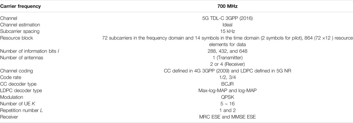
TABLE 2. Simulation parameters.
In Figure 2, the performance of NOMA is evaluated for CC and LDPC. The number of information bits is 432 and the repetition number is 2. MMSE ESE detection is applied with
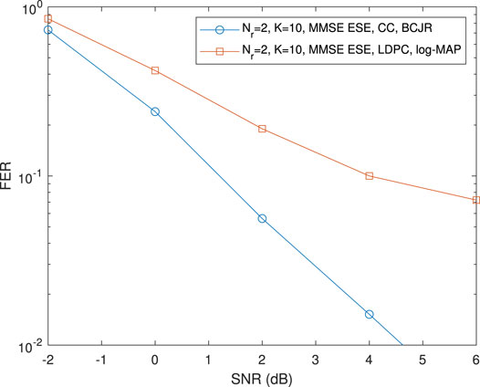
FIGURE 2. NOMA performance for channel coding with CC and LDPC, I = 432, L = 2, TDL-C.
To find out why NOMA with CC is superior to that with LDPC, in Figure 3 we evaluate the BER performance of CC and LDPC over an AWGN channel with QPSK modulation assumed. The number of information bits is 432 and the number of coded bits is 864, thus the code rate is 1/2. Although LDPC has better performance in low BER regions (BER
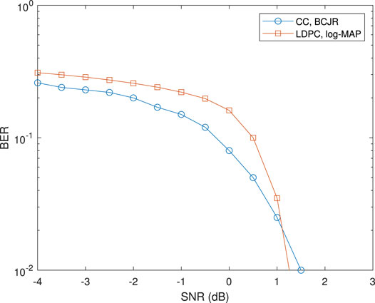
FIGURE 3. Performances of CC and LDPC for QPSK over AWGN channel, I = 432, code rate = 1/2.
In Figure 4, performances of NOMA with different channel decoders are compared. Here we use LDPC as the channel coding. LDPC is decoded by a log-MAP decoder and max-log-MAP decoder, respectively. It is observed that compared with NOMA with a log-MAP decoder, there is significant performance loss for NOMA with max-log-MAP decoder. When FER is equal to 0.1, the performance loss is about 8 dB. This means the transmitting power is only 20% of that of the original. Thus in practical implementation, the log-MAP decoder can be considered when power consuming is an important system design target we should consider.
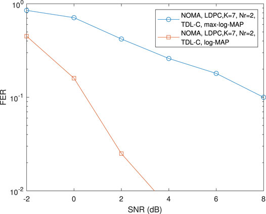
FIGURE 4. NOMA performance for log-MAP decoder and max-log-MAP decoder, I = 432, L = 2, LDPC.
In Figure 5, performances of NOMA with different channel decoders are compared where the code rate is 3/4. When the max-log-MAP decoder is applied there is significant performance loss for NOMA. The performance of NOMA with the max-log-MAP decoder is worse than that of the log-MAP decoder with about 1.8 dB at a FER of 0.01, even though the former supports five users and the latter supports six users. When the number of users is 5, NOMA with a log-MAP decoder has about a 5 dB gain over that with the max-log-MAP decoder at a FER of 0.2. There is an obvious error floor of FER for NOMA with the max-log-MAP decoder when number of users is 5. According to Figures 4, 5, NOMA with the log-MAP decoder has much better performance than that of the max-log-MAP decoder. The conclusion is independent of the code rate of the channel coding employed. From Figure 5, it is observed that NOMA with the log-MAP decoder supports a larger number of users than that with the max-log-MAP decoder.
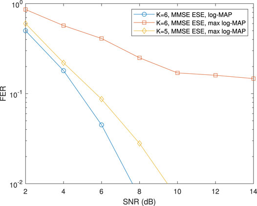
FIGURE 5. NOMA performance for log-MAP decoder and max-log-MAP decoder with LDPC, information bits I = 648, L = 2, code rate 3/4, QPSK.
To garner a deeper understanding of the performance of NOMA with different channel decoders, in Figure 6, the BER performances of LDPC with a log-MAP decoder and max-log-MAP decoder are evaluated for the case of single user. QPSK modulation is employed and the simulation is carried out over AWGN channel. It is found that performance of LDPC with a log-MAP has about a 0.7 dB gain over that of LDPC with a max-log-MAP. Lower BER means lower multi-user interference. Higher BER means larger multi-user interference. The log-MAP decoder has a smaller BER than that of the max-log-MAP decoder. In the iterative detection, the small BER difference between these two channel decoders is greatly amplified. Thus the performance of NOMA with the log-MAP decoder has a much better performance than that with the max-log-MAP decoder. In the OMA system, the performance loss is about 0.7 dB using the max-log-MAP decoder, which may be acceptable. However, the performance loss is about 8 dB at a FER of 0.1 according to the simulation result in Figure 4. Thus when the target is to support large number of UE connections, the log-MAP decoder should be applied in NOMA.
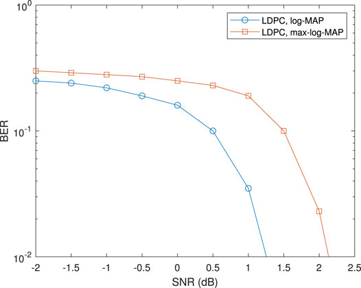
FIGURE 6. LDPC performance for log-MAP decoder and max-log-MAP decoder, information bits I = 432, L = 2, code rate 1/2, QPSK, AWGN channel.
In Figure 7, the MRC ESE detector and MMSE ESE detector are evaluated for NOMA. In MRC ESE, no matrix inversion operation is needed, thus it has smaller complexity compared with the MMSE ESE detector where matrix inversion operation is needed. When the number of users is 8, MMSE ESE detector has about 0.7 dB gain compared with that of the MRC ESE detector. The performance gap is small due to low multi-user interference in this case. When the number of users increases to 10, performance of the MMSE ESE detector is much better than that of MRC ESE. The reason is that, in this case, multi-user interference is high. Multi-user interference can be effectively reduced by an MMSE ESE detector, while MRC ESE only combines the desirable user’s signals. The capability of multi-user interference suppression for MRC ESE is weak.
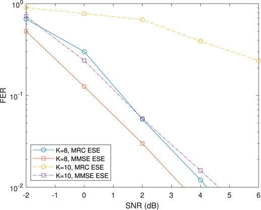
FIGURE 7. NOMA performance for MRC ESE decoder and MMSE ESE decoder, I = 432, L = 2, CC.
In Figure 8, the effect of repetition number on the performance of NOMA is shown. By using repetition, the same bit is spread on several resource elements. At the receiver side, the logarithm likelihood ratios of the same bit are accumulated to increase SINR so as to suppress the multi-user interference. With the assumption of the same number of information bits, when the repetition number is 1, the rate of the channel coding is small, thus coding gain can be achieved. As we can see when the number of users is 6, multi-user interference is low and there is a small gain for NOMA with a repetition number of 1 compared with that of a repetition number of 2. While when the number of users is 14, multi-user interference is high. NOMA with a large number of repetitions has better capability for multi-user interference suppression than that with a small number of repetitions. NOMA with a repetition number of 2 can reach a FER of 0.01 while NOMA with a repetition number of 1 shows an error floor at FER close to 0.1. When the number of users is large, a large number of repetitions is preferred.
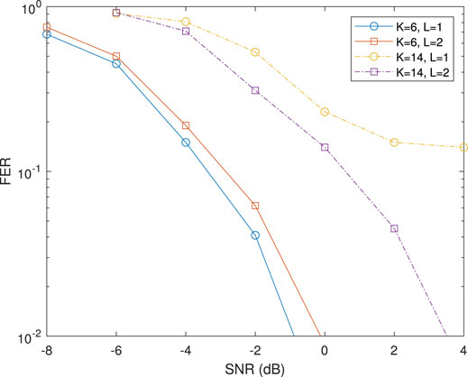
FIGURE 8. NOMA performance for different numbers of repetitions, I = 288, L = 1 and 2, LDPC, log-MAP decoder.
In Figure 9, the performance of NOMA with different
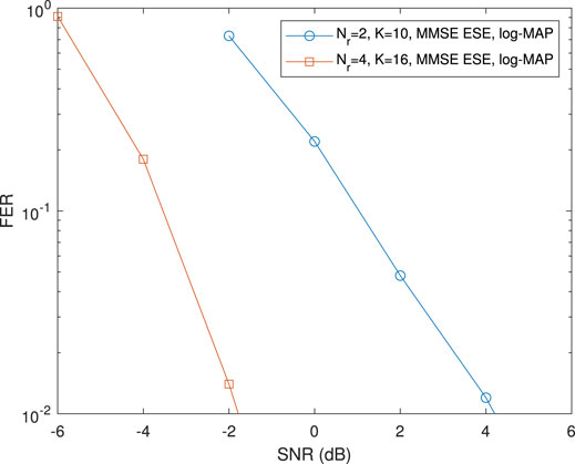
FIGURE 9. NOMA performance for different numbers of receiver antennas, I = 432, L = 2.
5 Conclusion
NOMA is an essential enabling technology for B5G systems which can fulfill the challenging requirements of mMTC. In this paper, we evaluate different factors, such as channel encoding, channel decoding, multi-user detector, repetition number, and the number of receiver antennas, on the performance of NOMA. According to the analysis and simulation results, it is found that CC is superior to LDPC for NOMA when code length is moderate. When the number of users is large, there is serious multi-user interference. In this case, a large number of repetitions, an optimal channel decoder, and a more advanced multi-user detector are preferred. By increasing the number of receiver antennas, the capability of multi-user interference suppression is greatly enhanced, thus the performance of NOMA can be significantly boosted. In the system design, these factors should be considered jointly to fulfill the requirements of B5G systems.
Data Availability Statement
The raw data supporting the conclusions of this article will be made available by the authors, without undue reservation.
Author Contributions
CY contributed to the conception and design of the study. CY organized the database, performed the algorithm descriptions, and wrote the first draft of the manuscript. WL and HY wrote and edited the manuscript. All authors contributed to manuscript revision, read, and approved the submitted version.
Conflict of Interest
The authors declare that the research was conducted in the absence of any commercial or financial relationships that could be construed as a potential conflict of interest.
Publisher’s Note
All claims expressed in this article are solely those of the authors and do not necessarily represent those of their affiliated organizations, or those of the publisher, the editors and the reviewers. Any product that may be evaluated in this article, or claim that may be made by its manufacturer, is not guaranteed or endorsed by the publisher.
References
3GPP (2009). Evolved Universal Terrestrial Radio Access (E-UTRA); Multiplexing and Channel Coding. Technical Specification (TS) 36.212 3rd Generation Partnership Project (3GPP).
3GPP (2001). GSM/EDGE Channel Coding. Technical Specification (TS) 45.003 3rd Generation Partnership Project (3GPP).
3GPP (2005). IEEE Standard for Local and Metropolitan Area Networks - Part 16: Air Interface for Fixed and Mobile Broadband Wireless Access Systems - Amendment for Physical and Medium Access Control Layers for Combined Fixed and Mobile Operation in Licensed Bands. Technical Specification (TS) 38.812 3rd Generation Partnership Project (3GPP).
3GPP (2012). Multiplexing and Channel Coding (FDD). Technical Specification (TS) 25.212 3rd Generation Partnership Project (3GPP).
3GPP (2018a). NR; Physical Channels and Modulation. Technical Specification (TS) 38.211 3rd Generation Partnership Project (3GPP).
3GPP (2016). Study on Channel Model for Frequency Spectrum above 6 GHz. Technical Report (TR) 38.900 3rd Generation Partnership Project (3GPP).
3GPP (2017). Study on New Radio (NR) Access Technology Physical Layer Aspects. Technical Specification (TS) 38.802 3rd Generation Partnership Project (3GPP).
3GPP (2018b). Study on New Radio (NR) Access Technology Physical Layer Aspects. Technical Report (TR) 38.812. 3rd Generation Partnership Project (3GPP).
Bahl, L., Cocke, J., Jelinek, F., and Raviv, J. (1974). Optimal Decoding of Linear Codes for Minimizing Symbol Error Rate (Corresp.). IEEE Trans. Inform. Theor. 20, 284–287. doi:10.1109/TIT.1974.1055186
Dai, L., Wang, B., Yuan, Y., Han, S., Chih-Lin, I., and Wang, Z. (2015). Non-orthogonal Multiple Access for 5G: Solutions, Challenges, Opportunities, and Future Research Trends. IEEE Commun. Mag. 53, 74–81. doi:10.1109/MCOM.2015.7263349
Hagenauer, J., and Hoeher, P. (1989). “A Viterbi Algorithm with Soft-Decision Outputs and its Applications,” in IEEE global telecommunications conference and exhibition ‘communications technology for the 1990s and beyond’, Dallas, TX, USA, 27–30 November 1989, 1680–1686. doi:10.1109/GLOCOM.1989.64230
Hu, Y., Liang, C., Liu, L., Yan, C., Yuan, Y., and Ping, L. (2019). Interleave-division Multiple Access in High Rate Applications. IEEE Wireless Commun. Lett. 8, 476–479. doi:10.1109/LWC.2018.2876538
Li Ping, L. (2005). Interleave-division Multiple Access and Chip-By-Chip Iterative Multi-User Detection. IEEE Commun. Mag. 43, S19–S23. doi:10.1109/MCOM.2005.1452830
Li Ping, L., Lihai Liu, L., Keying Wu, K., and Leung, W. K. (2006). Interleave Division Multiple-Access. IEEE Trans. Wireless Commun. 5, 938–947. doi:10.1109/TWC.2006.1618943
Liang, C., Hu, Y., Liu, L., Yan, C., Yuan, Y., and Ping, L. (2018). “Interleave Division Multiple Access for High Overloading Applications,” in IEEE international symposium on Turbo codes & iterative information processing conference (ISTC), Hong Kong, China, November 25–29, 2018. doi:10.1109/ISTC.2018.8625297
R1-1608755 (2016). LLS Results of PDMA with Realistic Channel Estimation. Lisbon: Technical proposal, 3rd Generation Partnership Project (3GPP).
R1-1612574 (2016). Link Level Simulation Results for IGMA. Reno: Technical proposal, 3rd Generation Partnership Project (3GPP).
R1-1801416 (2018). Typical Multi-User Receivers for NOMA. Athens: Technical proposal, 3rd Generation Partnership Project (3GPP).
R1-1803615 (2018). Key Processing Modules at Transmitter Side for NOMA. Sanya: Technical proposal, 3rd Generation Partnership Project (3GPP).
R1-1803665 (2018). Preliminary LLS Evaluation Results for mMTC Scenario. Sanya: Technical proposal, 3rd Generation Partnership Project (3GPP).
R1-1807073 (2018). Transmitter Design of UGMA. Busan: Technical proposal, 3rd Generation Partnership Project (3GPP).
R1-1808049 (2018). Discussion On the Design of SCMA. Gothenburg: Technical proposal, 3rd Generation Partnership Project (3GPP).
R1-1808054 (2018). Evaluation Results for mMTC Scenario. Gothenburg: Technical proposal, 3rd Generation Partnership Project (3GPP).
R1-1808968 (2018). Considerations on NOMA Transmitter. Gothenburg: Technical proposal, 3rd Generation Partnership Project (3GPP).
R1-1808975 (2018). TX Schemes for NoMA. Gothenburg: Technical proposal, 3rd Generation Partnership Project (3GPP).
Richardson, T. J., Shokrollahi, M. A., and Urbanke, R. L. (2001). Design of Capacity-Approaching Irregular Low-Density Parity-Check Codes. IEEE Trans. Inform. Theor. 47, 619–637. doi:10.1109/18.910578
Valenti, M. C., and Sun, J. (2001). The Umts Turbo Code and an Efficient Decoder Implementation Suitable for Software Defined Radios. Int. J. Wireless Inf. Networks 8, 203–215. doi:10.1023/A:1017925603986
Wu, Y., Wang, C., Chen, Y., and Bayesteh, A. (2017). Sparse Code Multiple Access for 5g Radio Transmission. IEEE vehicular technology conference, Toronto, ON, Canada, 24–27 September 2017, 1–6. doi:10.1109/VTCFall.2017.8288106
Wu, Y., Zhang, S., and Chen, Y. (2015). Iterative Multiuser Receiver in Sparse Code Multiple Access Systems. IEEE international conference on communications, London, UK, 8–12 June 2015, 2918–2923. doi:10.1109/ICC.2015.7248770
Yan, C., and Yuan, Y. (2019). Spreading Based Multi-branch Non-orthogonal Multiple Access Transmission Scheme for 5g. IEEE vehicular technology conference, Kuala Lumpur, Malaysia, 28 April –1 May 2019, 1–5. doi:10.1109/VTCSpring.2019.8746411
Yan, C., Yuan, Z., Li, W., and Yuan, Y. (2016). Non-orthogonal Multiple Access Schemes for 5g. ZTE Commun. 14, 11–16. doi:10.3969/j.issn.1673-5188.2016.04.002
Keywords: non-orthogonal multiple access, massive machine type communications, iterative detection, beyond fifth generation, interleaver-division multiple access
Citation: Yan C, Liu W and Yuan H (2021) Numerous Factors Affecting Performance of NOMA for Massive Machine Type Communications in B5G Systems. Front. Comms. Net 2:689530. doi: 10.3389/frcmn.2021.689530
Received: 01 April 2021; Accepted: 28 May 2021;
Published: 02 August 2021.
Edited by:
Minghua Xia, Sun Yat-Sen University, ChinaReviewed by:
Xiaoming Dai, University of Science and Technology Beijing, ChinaZongze Li, The University of Hong Kong, China
Copyright © 2021 Yan, Liu and Yuan. This is an open-access article distributed under the terms of the Creative Commons Attribution License (CC BY). The use, distribution or reproduction in other forums is permitted, provided the original author(s) and the copyright owner(s) are credited and that the original publication in this journal is cited, in accordance with accepted academic practice. No use, distribution or reproduction is permitted which does not comply with these terms.
*Correspondence: Chunlin Yan, eWNsMTAyM0Bob3RtYWlsLmNvbQ==