 Chu-Yuan Zhang
 Rong-Bing Zhao1*
 Dong Zhang
 Wei-Hua Shang-Guan
- 1Shanghai Astronomical Observatory, Chinese Academy of Sciences, Shanghai, China
- 2University of Chinese Academy of Sciences, Beijing, China
The ionosphere is an important component of near-Earth space that has a significant impact on communication and navigation. Furthermore, the total electron content (TEC) of the ionosphere is a widely used parameter in near-Earth plasma environment studies. A design of a digital beacon receiver system for automatically measuring TEC is presented. Universal Software Radio Peripheral (USRP) hardware equipment with software-defined radio technology was used in the tri-band beacon digital receiver to receive and rapidly preprocess beacon signals from satellites in different frequency bands. A software system is built to implement the automatic control of the receiver and to enable data processing of the preprocessed data in order to obtain its phase information and derive the TEC. The tri-band digital beacon receiver system is experimentally proven to automatically detect and archive transit satellites in real time, automatically receive and process satellite beacon signals with recording, and automatically generate TEC measurement results.
1 Introduction
As an important part of the near-Earth space, the ionosphere blocks high-energy particles and solar radiation from the universe. Total electron content (TEC) is one of the most significant parameters of the ionosphere, which can reflect ionospheric changes and ionospheric anomalies, and can be used to study the relationship between ionospheric changes in communications and natural phenomena.
There are many ways to measure TEC. TEC along the propagation path and signal scintillation caused by the irregular structure of the wave path can be obtained by measuring effects such as the Doppler shift or rotation of the polarization plane as the satellite signal propagates through the ionosphere. With ionospheric tomography, the ionosphere is scanned using satellite beacons, thus observing the distribution of ionospheric electron density and its variation with time. Bernhardt and Siefring (2006) designed tri-band satellite beacon signal receivers to complete the ionospheric lamination technique and increase stability compared to dual-band receivers. Satellite double-band beacon signals can also be received using GPS equipment on the ground, and the ionospheric TEC and electron density distribution can be determined by scanning the ionosphere based on the dispersion effect of the ionosphere on radio waves. Mannucci et al. (1998) calculated TEC using GPS receiverinversion and generated a global map of the TEC structure.
Previously, both Yamamoto (2018) and Vierinen et al. (2014) designed dual-band digital signal receivers for TEC measurements. They only received satellite beacon signals at 150 MHz and 400 MHz and applied the phase information of the signals at both frequencies to perform TEC calculations. In contrast, the tri-band beacon signal receiver we designed can receive radio signals of three frequency bands, 150, 400, and 1,066.67 MHz, emitted by the tri-band beacon signal instrument carried by the low-orbit satellite. This method of studying the ionosphere has the advantages of long-term continuity in time and a wide detection range. Moreover, it can effectively monitor the temporal and spatial changes in the large-scale structure of the ionosphere and reveal the fine structure of ionospheric irregularities and their change patterns. In addition to increasing the receiving frequency band, the digital receiver approach is continued, using off-the-shelf hardware Universal Software Radio Peripheral (USRP) and libraries in the GNU Radio software-defined radio platform to realize the preprocessing of digital signals (Patton, 2007). Digital receivers are more stable than traditional analog receivers. Digital receivers convert analog signals into digital signals and then process the digital signals afterward. This processing reduces the effects of gain variations, DC level drift, and non-linear distortion in analog circuits and has the advantage of being programmable and easy to store.
The paper is structured as follows: Section 2 describes the reasons and methods for calculating TEC values by using the phase information of two frequencies. Section 3 describes the hardware system component units and parameters of the tri-band signal receiver. Section 4 describes the design and implementation of the software system. Section 5 summarizes the functions of the whole system and the test results.
2 TEC calculation method
The most critical aspect of the entire tri-band beacon reception system is the TEC analysis. The evolution of TEC is as follows: n is the plasma refractive index whose calculation formula is
where cp is the phase speed, c is the speed of light equal to 2.998 × 10⁸m/s, and N is the electron density in the plasma. A is a constant of value 80.6m3s−2calculated using Eq. 2.
Here, the dielectric constant ɛ0, the charge e, and mass of the electron m are fixed constants.The electromagnetic wave emitted by the satellite beacon signaler at position x = 0 propagates along x with phase velocity cp and frequency f. The electric field amplitude is described as
The electromagnetic wave of the beacon signal travels in the direction of Z. The satellite is located at position Z = 0, which corresponds to position Z = L at the ground station, and the electromagnetic wave travels a distance of L. From this, we can determine the phase of the signal transmitted from the satellite received at the ground station with Z = L as
Eq. 1 is substituted into Eq. 4, and the phase is added. There is a time-dependent error term r(t) in the measurement of the satellite distance range, and the error term is substituted into Eq. 4 along with Eq. 1; then, the measured phase is given as
The phase information is measured separately with two beacon signals of different frequencies, and the TEC value can be obtained by eliminating other unneeded terms after the operation. The formula is expressed as follows:
The aforementioned equation is the calculation process of TEC, and the error r(t) can also be calculated, which is not discussed in detail in this study.
3 Tri-band beacon digital receiver composition
The tri-band beacon digital receiver consists of a receiving antenna unit, a preamplifier unit, and a digital receiver unit. In the tri-band beacon digital receiver, the reception and signal preprocessing of satellite UHF, VHF, and L-band beacon signals are completed. As shown in Figure 1, the signal enters the amplifier unit via the antenna. The signals from the different frequency bands then enter the digital receiver unit of the corresponding frequency band, where digital signal processing is carried out using software radio technology to realize processes such as down-conversion and AD sampling of the received signals and output into memory to complete the data recording.
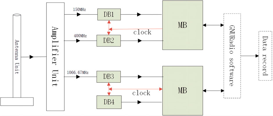
FIGURE 1. Tri-band beacon digital receiver flow diagram.
3.1 Receiving antenna unit
The antenna unit contains a triple orthogonal dipole antenna, which can receive satellite signals at three frequencies simultaneously, 50 MHz, 400 MHz, and 1,066.67 MHz (VHF, UHF, and L-band, respectively). The received radio signal will be converted to a level signal. In order to ensure that the equipment points to the zenith direction and achieves low-angle satellite signal reception, the tri-band beacon receiving antenna adopts the orthogonal dipole antenna technology, which consists of two mutually orthogonal dipole antennas. The impedance of the dipole antenna is 75 ohm, and the impedance changes after combining two dipole antennas. In order to realize the impedance matching of the antenna, as well as to realize the circular polarization omnidirectional radiation direction map, we add two feed signals with a 90 degree difference to two dipole antennas through the phase shift network and matching network so that the “∞” radiation dipole antenna becomes a circular omnidirectional radiation antenna. The 90 degree phase difference in the two dipole antennas of the lag and ahead of the situation determines the antenna circular polarization mode. The mutual influence between the antennas of the three dipole antennas is determined by the distance between the antennas. The correct mutual distance can reduce the mutual direct influence on the respective antenna radiation direction map. Since the dipole antenna characteristics are clear, the antenna must be installed on the metal base plate in order to obtain a good radiation effect. As a result, the three-frequency point antenna using the cross-plug coupled antenna is placed on the metal platform with 1.5 m length and 1.5 m width. The length of the antenna is determined by the wavelength of each band, as shown in Figure 2. The length of the antenna for receiving VHF signals is 95 cm; the length of the antenna for receiving UHF signals is 26.5 cm; and the length of the antenna for receiving L-band signals is 14 cm.
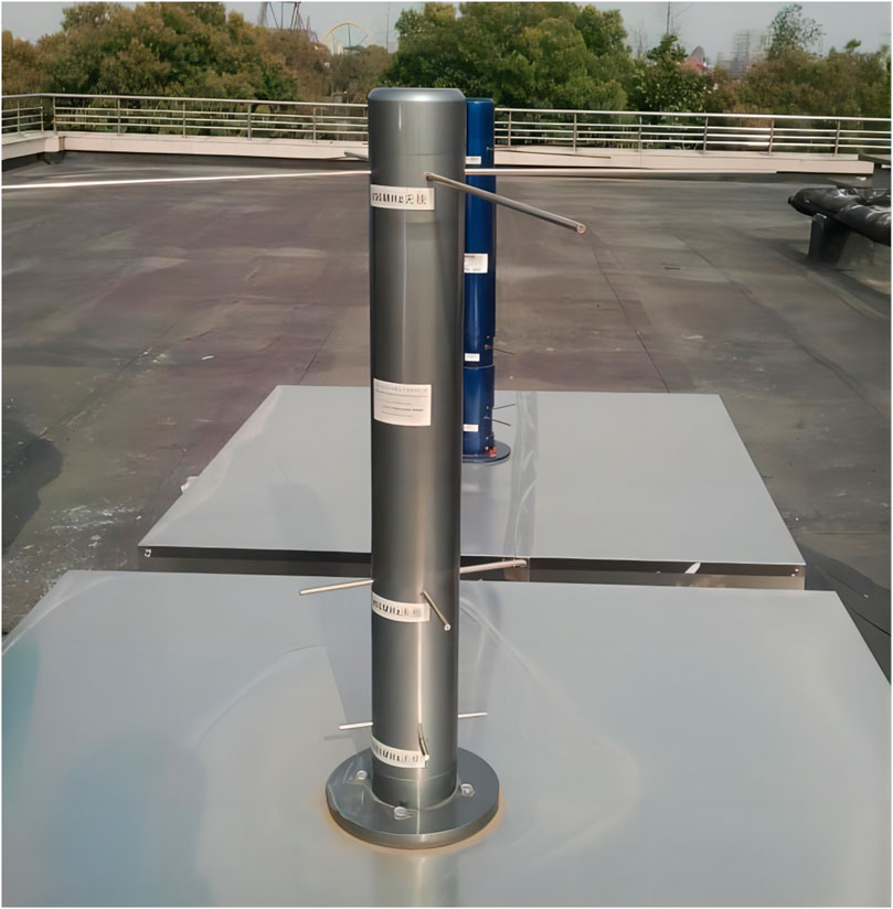
FIGURE 2. Tri-band antenna.
3.2 Amplifier unit
The amplifier is responsible for amplifying the received signal from the antenna. The signals of multiple frequency points are connected and amplified separately, and the amplified signals are connected by the digital receiving unit. The multi-frequency point amplifier consists of two parts, an outdoor unit and indoor unit, which are linked to each other by a cable of approximately 50 m. Our research shows that the bandwidth is no more than 5% of the frequency point, the rejection of each low-noise amplifier (LNA) to two frequency points is better than 25 dB, and the in-band gain fluctuation is less than 1 dB.
3.3 Digital receiver unit
The digital acquisition unit includes two NI Ettus N210 USRP motherboards, GPSDO module, GPS time, and GNU Radio software. The NI Ettus N210 USRP is a high-performance radio frequency system-on-chip (RFSoC) platform with broad radio frequency (RF) spectrum access and large bandwidth data transmission capability. It has two programmable RF receivers and transmitters that support digital signal processing with bandwidths up to 60 MHz. Here, two daughter boards are installed on top of the two USRP motherboards for receiving and processing three RF signals. After the signal is sampled and rectified by AD, it is connected to a computer via Ethernet, and the acquired data are recorded on the computer’s hard disk using a software-defined radio (SDR) kit. The picture of a digital receiver unit is shown in Figure 3.
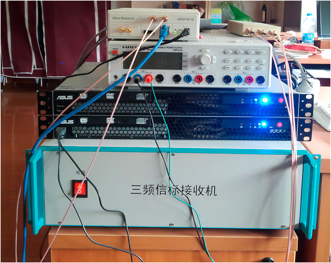
FIGURE 3. Digital receiver unit.
4 Software system design and implementation
4.1 Design
To achieve fully automated observation operation as well as data processing, the main functions of the software need to include automatic star orbit prediction, satellite triple-frequency channel spectrum display, Doppler extraction, automatic ionospheric electron density decomposition, Doppler information reconstruction of ionospheric TEC and S4 parameters, and data results into graphical display.
4.2 Implementation
According to the design, we developed four software modules: the satellite orbit acquisition module, satellite forecast module, data acquisition program module, and data processing program module. The runtime flowchart is shown in Figure 4. Each function is implemented using a separate process, and the processes interact with each other through files. The black boxes indicate the processes, and the purple parallelogram boxes indicate the files transferred by the processes interacting with each other.
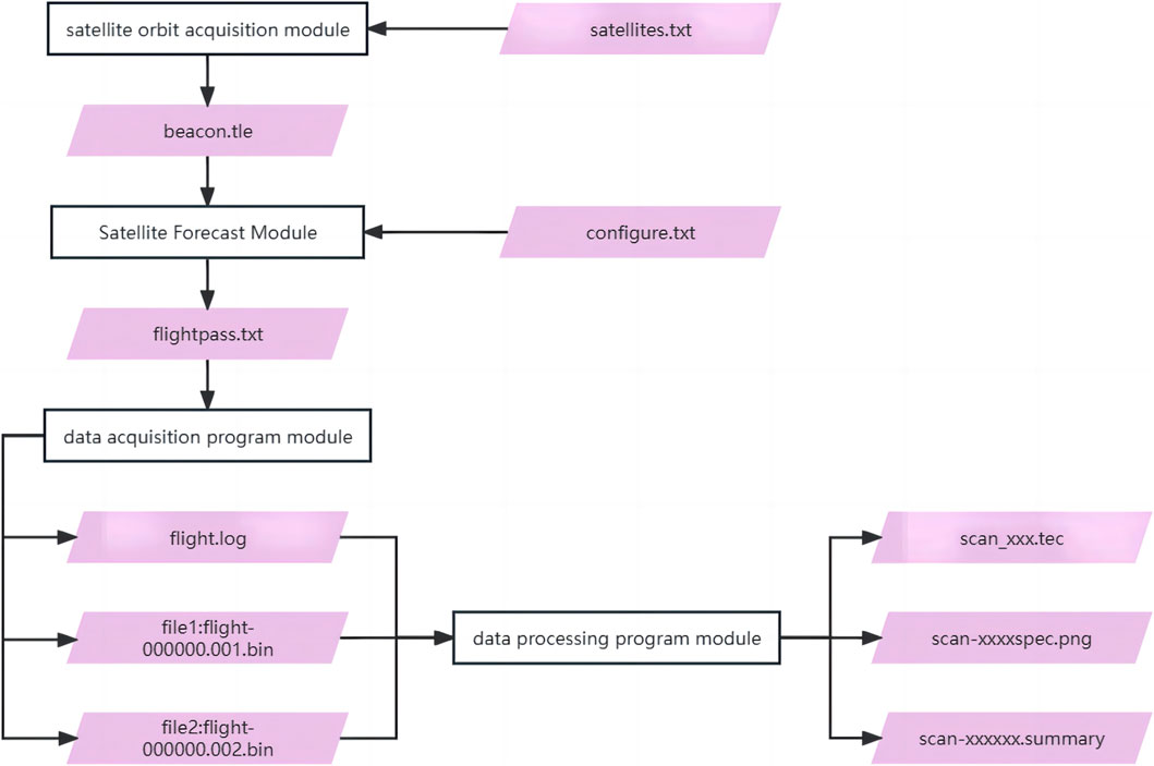
FIGURE 4. Runtime flowchart.
First, the satellite orbit acquisition module can calculate the two rows of satellite roots that pass over the receiver within 24 h, and the beacon signal can be received by the receiver through the satellite txt file and output through the beacon.tle file. Second, the satellite forecast module uses the two rows of satellite root information and the configure.txt file to calculate the satellite orbit information by using the SGP method. This orbit information is output through the flightpass.txt file, which includes the number of satellites, names, dates, satellite appearance and departure times, elevation angles, and azimuth angles. Third, the data acquisition module is based on the orbit information file. When the satellite in the flightpass.txt file passes within the visible range of the receiver, this program will change the receiver to the data receiving state, and the whole satellite signal receiving process will last for approximately 15–20 min. Both the flight-000000.001.bin file, flight-000000.002.bin and the flight.log file are output. The flight file records the real and imaginary part values of the quadrature signals for the three bands, and the flight.log file records each satellite reception. Finally, the data processing program module parses and processes the data to output the files scan_xxx.tec, scan-xxxxnspec.png, and scan-xxxxxx.summary. The scan_xxx.tec file contains the relative TEC values given every 0.0125 s, the scan-xxxxspec.png file contains the azimuth and altitude angles of the satellite, as well as the 150 MHz and 400 MHz signal spectra, and the scan-xxxxxx.summary file contains the relative ionospheric values and fitted residual values.
5 Results
Our research indicates that the frequency bias range of the tri-band beacon receiver designed in this paper is from −2.2 × 10⁻⁴ Hz to +1.1 × 10⁻⁴ Hz. If the frequency bias of the satellite is out of this range, it will affect the regular operation of the receiver, so that satellites with frequency bias beyond this range cannot be received by this receiver. In addition, the noise intensity of the satellite signals in the three bands should not exceed 4.2 dB. The signals of the following satellites can be received: OSCAR 25, COSMOS 2407, COSMOS 2463, COSMOS 2414, RADCAL, DMSP F15, and other low-orbiting satellites. The signals of satellites those transmit at carrier frequencies of 150 MHz and 400 MHz, fly at altitudes of 800–1,200 km, have a flight period of 100–110 min, and travel in a north–south direction around the polar axis can also be received. The 1,066.67 MHz band is not currently used for observations. After the receiver successfully locks onto the satellite, the signal reception duration lasts for approximately 15 min–20 min, depending on the direction of the satellite movement and the relative position of the receiving stations. Figure 5 shows the distance, bearing and elevation trajectories, signal spectrum, relative ionospheric map, and relative ionospheric residual map of the satellite COSMOS 2407.
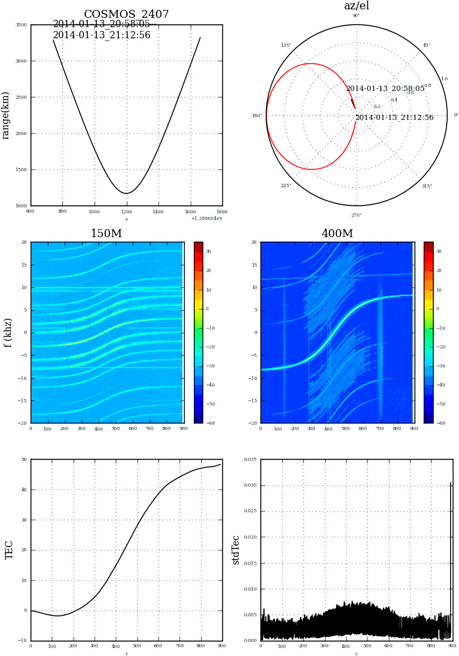
FIGURE 5. Measurement results.
6 Summary
In this paper, the tri-band beacon digital receiver system is designed with two parts. One is the tri-band beacon digital receiver which mainly receives the satellite beacon signal and performs preprocessing of the received signals. The other part is the software part which functions to complete signal post-processing and automatic control. The tri-band beacon digital receiver system can remotely realize automatic real-time tracking observation, and according to the results mentioned in the previous section, the system works well and can obtain accurate measurement results. In the future, three bands, 150 MHz, 400 MHz, and 1,066.67 MHz, will be used for further observations and will further improve the observation accuracy.
Data availability statement
The original contributions presented in the study are included in the article/Supplementary Material; further inquiries can be directed to the corresponding author.
Author contributions
C-YZ: conceptualization, methodology, hardware, software, formal analysis, and writing—original draft. R-BZ: conceptualization, funding, software, resources, supervision, and writing—review and editing. DZ: software, validation, and writing—original draft. D-MY: writing—review and supervision. Y-JW: hardware and validation. W-HS-H: software, visualization, and investigation. ZY: data analysis. All authors contributed to the article and approved the submitted version.
Funding
This work was supported by the National SKA Program of China (No. 2020SKA0120104).
Conflict of interest
The authors declare that the research was conducted in the absence of any commercial or financial relationships that could be construed as a potential conflict of interest.
Publisher’s note
All claims expressed in this article are solely those of the authors and do not necessarily represent those of their affiliated organizations, or those of the publisher, the editors, and the reviewers. Any product that may be evaluated in this article, or claim that may be made by its manufacturer, is not guaranteed or endorsed by the publisher.
References
Bernhardt, P. A., and Siefring, C. L. (2006). New satellite-based systems for ionospheric tomography and scintillation region imaging. Radio Sci.41, RS5S23–14. doi:10.1029/2005RS003360
Mannucci, A. J., Wilson, B. D., Yuan, D. N., Ho, C. H., Lindqwister, U. J., and Runge, T. F. (1998). A global mapping technique for gps-derived ionospheric total electron content measurements. Radio Sci.33, 565–582. doi:10.1029/97RS02707
Patton, L. K. (2007). A gnu radio based software-defined radar. United States: Wright State University, 125.
Vierinen, J., Norberg, J., Lehtinen, M. S., Amm, O., Roininen, L., Vüününen, A., et al. (2014). Beacon satellite receiver for ionospheric tomography. Radio Sci.49, 1141–1152. doi:10.1002/2014RS005434
Keywords: tri-band beacon digital receiver, ionosphere total electron content, software-defined radio, Universal Software Radio Peripheral, satellite
Citation: Zhang C-Y, Zhao R-B, Zhang D, Yu D-M, Wu Y-J, Shang-Guan W-H and Yan Z (2023) A tri-band terrestrial beacon digital receiver system for TEC measurements. Front. Astron. Space Sci. 10:1167331. doi: 10.3389/fspas.2023.1167331
Received: 16 February 2023; Accepted: 15 June 2023;
Published: 29 June 2023.
Edited by:
Sampad Kumar Panda, KL University, IndiaReviewed by:
Jeff Kuhn, University of Hawaii, United StatesPunyawi Jamjareegulgarn, King Mongkut’s Institute of Technology Ladkrabang, Thailand
Copyright © 2023 Zhang, Zhao, Zhang, Yu, Wu, Shang-Guan and Yan. This is an open-access article distributed under the terms of the Creative Commons Attribution License (CC BY). The use, distribution or reproduction in other forums is permitted, provided the original author(s) and the copyright owner(s) are credited and that the original publication in this journal is cited, in accordance with accepted academic practice. No use, distribution or reproduction is permitted which does not comply with these terms.
*Correspondence: Rong-Bing Zhao, emhhb3JiQHNoYW8uYWMuY24=