 Md Yeakub Ali
 Ali Lalbakhsh1
 Khushboo Singh
- 1School of Engineering, Macquarie University, Sydney, NSW, Australia
- 2School of Electrical and Data Engineering, University of Technology Sydney(UTS), Sydney, NSW, Australia
This article introduces a planar, highly transmissive, 3-D printable metastructure with a low profile for enhancing the far-field radiation performance of conventional electromagnetic band-gap (EBG) resonator antennas. The proposed near-field phase transforming metastructure (PTM) is developed by employing the near-field phase transformation approach that transforms the non-uniform phase of a conventional EBG resonator antenna into a nearly uniform one and enhances the far-field radiation pattern. The novelty of this paper lies in reducing the height of the phase-transforming structure compared to state-of-the-art structures with better performance. The metastructure’s low profile is realized by incorporating metal inside the dielectric materials. The proposed PTM comprises two types of unit cells made of metal and dielectric material to achieve a wide range of phase coverage. All the phase transforming unit cells used are highly transmitting as their transmission coefficient
1 Introduction
In recent years, metasurface, also known as metastructure, a class of 2-D metamaterials (Duan et al., 2019; Tang et al., 2022), has drawn significant attraction to researchers in the field of electromagnetics for their unique electromagnetic characteristics. They are now being employed in wireless communication to cater to the demands, such as high gain and bandwidth of emerging wireless communication technologies (Afzal et al., 2018; Pepino et al., 2018). They are also used in multi-functional antennas for polarization conversion and reconfiguration of frequency and radiation patterns of antennas (Ahmed et al., 2023b; Ni et al., 2024). The metasurface concept has also been exploited to improve the radiation characteristics of aperture antennas. To avoid conventional problems of high gain antennas, such as bulky structures and lossy feeding networks (Afzal and Esselle, 2015; Ahmed et al., 2021; Zhu et al., 2017), metasurfaces are placed on the top of the radiative aperture to modify the aperture phase distribution. In this regard, reflectarrays and transmit arrays (Yang et al., 2023; Farias et al., 2022; Su et al., 2023; Pham et al., 2020) are formed by integrating metasurfaces in the far-field regions of the aperture antennas. Although they are low-loss structures, their main drawback lies in their relatively large dimensions, which can constrain their practical applications.
Several approaches have been devised by the researchers for enhancing the radiation performance of antennas, such as new material (Esfandiyari et al., 2022; Esfandiari et al., 2022), frequency selective surfaces (Lalbakhsh et al., 2022a; Das et al., 2022), and the use of artificial intelligence for developing new electromagnetic materials (Lalbakhsh et al., 2022b). Addressing the challenges associated with their traditional counterparts (Ren et al., 2022), electromagnetic band-gap resonator antennas (ERAs) (Ge et al., 2016; Costa et al., 2018; Oliner, 1993; Mateo-Segura et al., 2013; Konstantinidis et al., 2014), coupled with a metasurface, has become an alternative to conventional high-gain (16–25 dB) antennas (Comite et al., 2020). The traditional ERAs comprise a partially reflecting surface (PRS) and a ground plane that makes a resonance between these two planes at the operating frequency. The usage of ERAs in different applications, including mmWave communication, satellite communication, and radar, is increasing due to their advantageous characteristics, such as planar surface, simple structure, and easily implementable feeding system (Lalbakhsh et al., 2020).
One of the approaches to improve the radiation characteristics of aperture-type antennas is based on the near-field phase transformation principle (NFPT), which manipulates their near-field phase distribution by loading a metastructure to achieve the desired outcome (Zeb et al., 2016; Afzal et al., 2015; Konstantinidis et al., 2014; Pepino et al., 2018; Xie et al., 2019; Ahmed et al., 2023a; Lalbakhsh et al., 2016; Zhou et al., 2018; Baba et al., 2018). Utilizing NFPT creates a passive, low-loss, and low-profile structure, which can significantly improve antenna performance. Phase-transforming structures can be realized by using all-dielectric (Pepino et al., 2018; Hayat et al., 2019b), all-metal (Ahmed et al., 2024), and multi-layer printed structure (Nabeel et al., 2024; Li et al., 2024; Afzal and Esselle, 2015; Xie et al., 2019; Zhou et al., 2020). However, each type of structure is associated with at least one of the following drawbacks: heavy weight, high profile, polarization dependence, high cost, and high loss in high-frequency applications. This paper aims to design a metastructure with a low profile for radiation improvement of ERAs that can be fabricated at a low cost using additive manufacturing technologies.
In recent years, all-dielectric phase transforming structures have been realized from commercially available dielectric material blocks using subtractive manufacturing (SM) methods like computer numerical control (CNC). However, subtractive manufacturing is costly and leads to material wastage. Furthermore, certain customized structures can not be realized using subtractive manufacturing. Additive manufacturing (AM), commonly known as three-dimensional (3-D) printing, addresses the limitations of subtractive manufacturing. AM is increasingly prevalent across various sectors, including spacecraft, bio-medical equipment, and defense industries, due to its numerous advantages over traditional subtracting manufacturing processes (Delic and Eyers, 2020; Fasel et al., 2020; Busachi et al., 2017; Capel et al., 2018; Macdonald et al., 2014). The benefits of AM encompass rapid prototyping, the capability to produce highly customized and intricate structures, minimal waste during production, and the ability to assess design errors prior to final production (Hayat et al., 2019a).
In conjunction with advancements in Additive manufacturing technologies, the choice of materials for AM becomes crucial for specific applications where material properties significantly influence the performance of 3-D printed devices. Commonly employed 3-D printing materials include Acrylonitrile Butadiene Styrene (ABS), Polylactic Acid (PLA), Acrylonitrile Styrene Acrylate (ASA), and Thermoplastic Polyurethane (TPU) (Ponti et al., 2023). However, using such materials has encountered a few challenges, such as the material’s limited permittivity range (2.0–2.8) and high loss (Zhang et al., 2020; Hayat et al., 2020). To address those issues, the exploration of materials with a wider range of permittivity and low RF loss becomes essential. Notably, the application of recently developed PREPERM®ABS materials has increased remarkably in manufacturing high-frequency wireless communication devices. These thermoplastics are RF-graded and formulated to meet faster and high-frequency communication demands. Furthermore, this type of material offers a wide range of dielectric constants (2.0–22.0) and ensures stable operation over a wide range of frequencies with ultra-low RF loss
The phase-varying metastructures are typically realized either by varying the height of the same permittivity material or maintaining the same height of different permittivity materials (Hayat et al., 2019b). Commercially available materials (COTS) cannot provide a continuous variation of permittivity. Applying engineering techniques to the cell’s internal structure and synthesizing the host material, continuous variation of permittivity is achieved to produce a wide range of continuous phase delays. In this paper, continuous phase variation is realized through the incorporation of metal and air holes within the host dielectric material. This approach offers the advantage of creating a planar structure that is free from shadowing problems associated with non-planar structures.
The main contribution of this paper is to develop a wideband 3-D printable phase transforming metastructure for far-field radiation enhancement with a lower structure height
The next sections of this paper are structured as follows. The methodology to design the proposed phase transforming metastructure using near-field phase transformation and cell analysis is described in Section 2. The simulation result analysis, comparison, and benchmarking are shown in Section 3. Section 4 draws the conclusion of this paper.
2 Design methodology
The proposed phase-transforming metastructure can be implemented to enhance the performance of any aperture-type antenna, like a horn antenna, slot antenna, or patch antenna. For the proof-of-concept of the proposed PTM, a prototype with an EBG resonator antenna (ERA) is considered to operate at 12 GHz. The constituent parts of the classical ERA are the feed source, ground plane of metal (thickness = 1 mm), and partially reflecting surface (PRS). The distance between the ground and PRS is typically set to
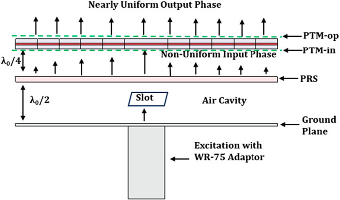
Figure 1. A schematic diagram of an ERA with the proposed phase transforming metastructure.
It is known that the performance of the classical ERA is limited due to the non-uniform phase distribution of the dominant electric field (Ali et al., 2024a). This non-uniformity can be minimized by placing the proposed PTM. The principle of near-field phase transformation (NFPT) is employed here to develop the proposed low-profile wideband PTM for ERA. Figure 2 shows a flow diagram of the design process of the proposed PTM. In this technique, a hypothetical plane is considered at a distance of 5 mm
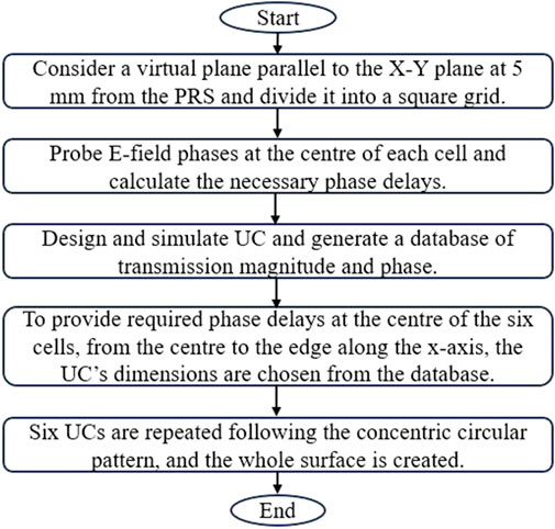
Figure 2. A flow diagram of the steps to design the proposed PTM.
To measure the phase at discrete points on top of the aperture, the input phase plane, PTM-in, is divided into
where
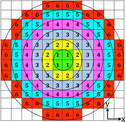
Figure 3. A view of the imaginary plane with square grids and cells location in a nearly concentric circular pattern.
The probed phases for the 6 cells and the required phase delays for them are mentioned in Table 1. Two types of unit cells, denoted by category-I and -II as shown in Figure 4, have been used to produce the required phase delay. Because one single category of cells is not capable of providing a wide range of transmission phase coverage with higher transmission coefficient magnitude. Six unit cells were selected based on the required phase delay to provide phase delay locally in the phase gradient metastructure.
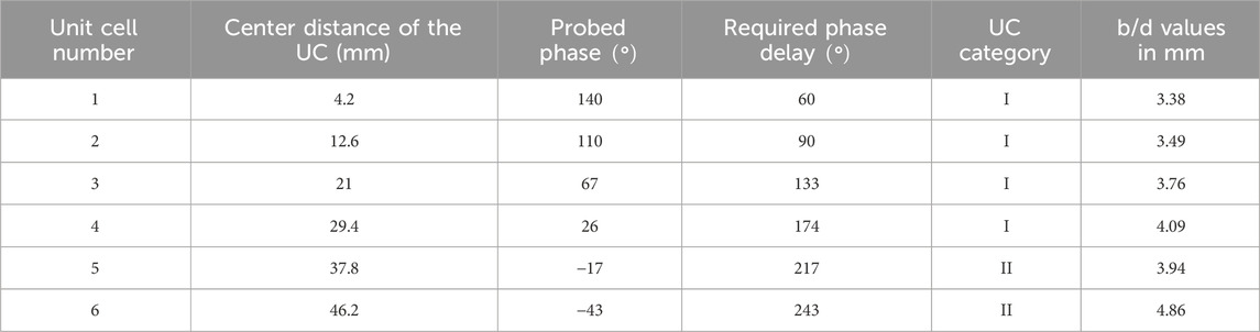
Table 1. Unit cell’s center distance, probed phases, necessary phase delays, and values of b/d for the unit cells.
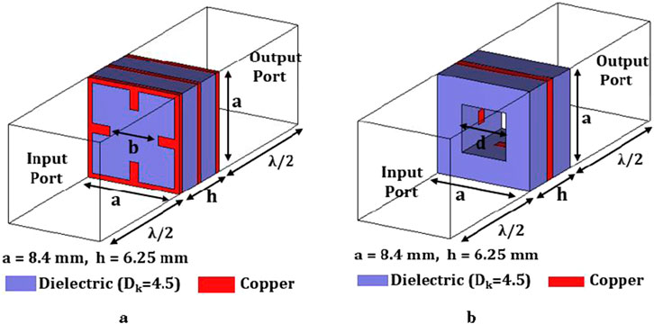
Figure 4. (a) Unit cell category-I (UC 1-4) (b) Unit cell category-II (UC 5-6).
2.1 Unit cell analysis
Unit cells are the fundamental building block of the metasurface, also called metastructure (Askari et al., 2020). The response of the metasurface is controlled by engineering the internal structure of the unit cell (UC). It is pivotal to analyze the performance of unit cells before designing a metastructure. The proposed phase transforming metastructure (PTM) consists of two categories of unit cells, category I and II. The reason for using hybrid cells is that one type of cell cannot provide a wide range of phases for phase correction, maintaining a transmission coefficient greater than −1 dB. The unit cells are made of dielectric materials (
To investigate the transmission and reflection characteristics of the unit cells shown in Figure 4, the unit cells are simulated by utilizing the unit cell boundary condition of EM solver, CST. The category-I unit cell is simulated with a parametric sweep of ‘b’ from 3 mm to 4.5 mm to prepare a database of transmission coefficient magnitude
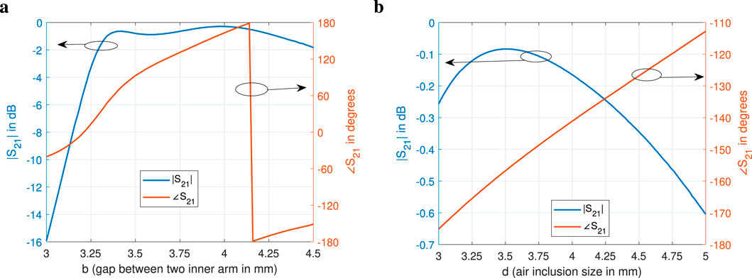
Figure 5. Transmission coefficient magnitude and phase (a) Unit cell category-I with the variation of “b” (b) Unit cell category-II with the variation of “d”.
The reflection
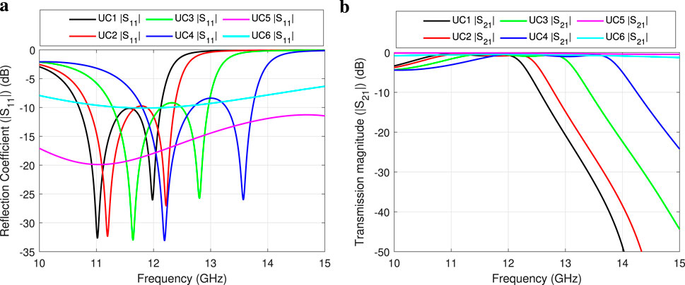
Figure 6. (a) Reflection coefficient magnitude (b) Transmission coefficient magnitude for the cells used in the proposed 3-D printed structure with different frequencies.
2.2 Proposed phase transforming metastructure
Based on the calculated required phase delay mentioned in Table 1 for phase correction, unit cells from 1 to 6 have been selected to provide the necessary phase delay. As the 2-D phase distribution above the aperture is considered circularly symmetric (Afzal et al., 2015), the unit cells from 1 to 6 are copied in a concentric circular pattern displayed in Figure 3 to cover the whole aperture. A perspective view of the proposed PTM is depicted in Figure 7 along with the base antenna. A few unit cells located in the corner of the aperture are ignored to reduce the material consumption for fabrication and the structure’s weight. Those cells have a minor impact on far-field performance. After completing the design, the near-field and far-field radiation performances were analyzed using full-wave simulation.
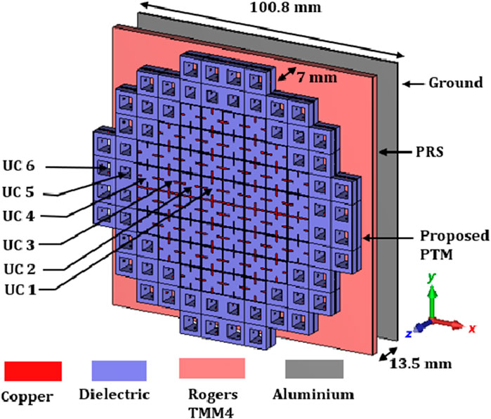
Figure 7. A perspective view of the proposed phase transforming metastructure with an ERA.
3 Result analysis
The three-dimensional structure of the proposed phase transforming metastructure with an EBG resonator antenna is simulated using the time domain solver of CST software with open boundary conditions and evaluated the performance.
In the ERA system without the proposed PTM, the dominant electric field’s
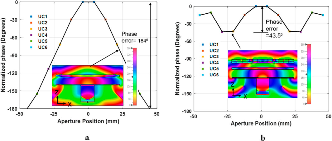
Figure 8. Dominant electric field
Figure 8b shows the phase distribution after near-field phase correction with the proposed PTM. The proposed PTM significantly reduced phase error to
A comparison of peak directivity in the E− and H-plane between ERA with and without loading the proposed PTM is depicted in Figure 9. The ERA with PTM provides peak directivity at 12.4 GHz. At 12.4 GHz, without the PTM, the ERA’s peak directivity is 11.4 dBi, but with the PTM, the directivity increases to 21.4 dBi. This substantial enhancement (10 dBi) in directivity is attributed to improved phase uniformity in the near-field region facilitated by the proposed PTM. This figure also compares directivity in the H-plane with and without the proposed PTM. The side lobe levels (SLLs) are lower in the H-plane than in the E-plane.
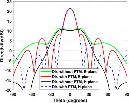
Figure 9. Peak directivity comparison between ERA with and without the proposed PTM in E− and H-plane at 12.4 GHz.
To validate the expected data derived from the simulation using CST microwave studio software, we simulated the proposed prototype using another commercial RF software, HFSS, and compared the results. The following figures compare some results from CST and HFSS.
Figure 10 depicts the variation of directivity and gain with the variation of frequency in the E-plane, illustrating the wideband functionality of the proposed planar PTM. The peak directivity of 21.4 dBi and peak gain of 20.7 dBi are obtained at 12.4 GHz with the proposed PTM. The slight shifting of the peak directivity occurs due to the loading effect of the phase-transforming structure, which is a common behavior of ERA (Afzal et al., 2018). Though the ERA system is designed for a single frequency, due to the wideband characteristics of the base antenna and unit cells, the ERA, equipped with the proposed PTM, operates effectively across a wide range of frequencies. The 3-dB directivity bandwidth spans from 10.9 GHz to 13.66 GHz, equivalent to 22.48%, showing the wideband operational capability of the PTM-based ERA. The directivity and gain versus frequency plot for the ERA without the proposed PTM is also shown in the same figure. This figure also shows directivity and gains results with the variation of frequency from HFSS software to show a comparison between the results from CST and HFSS. Directivity and gain results from CST software show good agreement with the results from HFSS.
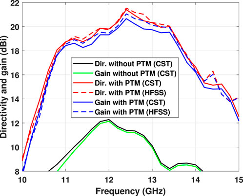
Figure 10. In E-plane, comparison of directivity and gain with the frequency between CST and HFSS results.
To show the stability of the radiation pattern across the operating frequency range, the directivity patterns in both the E− and H-planes are presented at some selected frequencies within the operational bandwidth. Figure 11 illustrates the co-polar and cross-polar components of the directivity in E-plane at 11 GHz, 11.6 GHz, 12.2 GHz, and 13.2 GHz, obtained from both CST and HFSS simulation. The SLLs in the E-plane are in the acceptable range (9 dB lower than the main beam) within the operating frequency range. The cross-polar components are lower than −15 dBi. The results from both software are compared. This figure shows a good alignment between the results from both software. Although minor discrepancies are observed in cross-polarized components, the overall level of suppression is nearly identical.
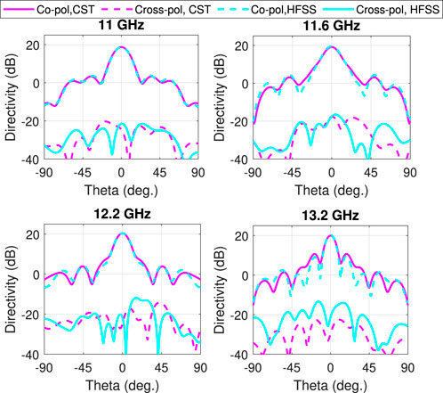
Figure 11. Co-polar and cross-polar components of directivity in E-plane at 11, 11.6, 12.2, and 13.2 GHz, results are provided from both CST and HFSS software.
The directivity components in the H-plane for the same frequencies using CST and HFSS software are shown in Figure 12. In the H-plane, the SLLs are at least 10 dBi less than the main beam peak within the operational bandwidth. The cross-polar components are below −18 dBi for all operating frequencies. From this figure, we can see a good alignment between the results from both software. Though there is a small difference in cross-polar components, the level of suppression is almost similar. The minor discrepancy between the results of CST and HFSS is due to the different numerical methods of analysis of each software and their calculation accuracy.
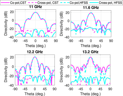
Figure 12. Co-polar and cross-polar components of directivity in H-plane at 11, 11.6, 12.2, and 13.2 GHz, results are provided from both CST and HFSS software.
Figure 13 shows a reflection coefficient comparison between the results from both CST and HFSS software. The ERA utilizing the proposed PTM demonstrates effective impedance matching across the operational frequency range of 10.9–13.66 GHz. For the system with PTM, the maximum return loss within the operating frequency range is −12.5 dB, and the −10 dB return loss matching bandwidth is greater than 40%. This figure shows a good alignment between the results from both software. So, from all the result analyses and comparisons, it is observed that there is a good alignment between the results from CST and HFSS.
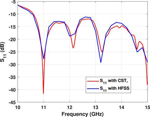
Figure 13. Reflection coefficient comparison of the proposed PTM-based ERA system using CST and HFSS.
The performance of our proposed PTM-based ERA is compared with some state-of-the-works reported in the literature, and a comparison table for benchmarking is shown in Table 2. This table clearly shows that the height of the proposed metastructure is lower (6.25 mm
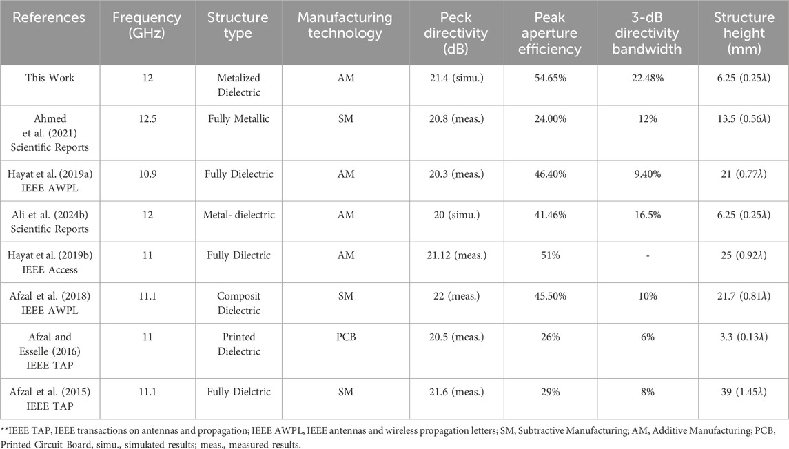
Table 2. Performance comparison with state-of-the-art structures.
4 Conclusion
A low-profile phase-transforming metastructure is demonstrated in this paper for far-field radiation improvement of ERA that can be manufactured using 3-D technology. The combination of metal and dielectric material in unit cell design plays a significant role in developing the lower-profile metastructure using the NFPT approach. All the cells used in the metastructure are highly transmissive (
Data availability statement
The original contributions presented in the study are included in the article/supplementary material, further inquiries can be directed to the corresponding author.
Author contributions
MA: Conceptualization, Formal Analysis, Investigation, Methodology, Writing – original draft. AL: Project administration, Supervision, Writing – review and editing. KS: Formal Analysis, Funding acquisition, Resources, Supervision, Writing – review and editing. ST: Formal Analysis, Software, Writing – review and editing. SM: Supervision, Writing – review and editing.
Funding
The author(s) declare that financial support was received for the research and/or publication of this article. This work is supported by The International Research Training Program (RTP) scholarship funded by the Commonwealth Government and Macquarie University in Australia.
Conflict of interest
The authors declare that the research was conducted in the absence of any commercial or financial relationships that could be construed as a potential conflict of interest.
Generative AI statement
The author(s) declare that Generative AI was used in the creation of this manuscript. Checked the grammatical errors.
Publisher’s note
All claims expressed in this article are solely those of the authors and do not necessarily represent those of their affiliated organizations, or those of the publisher, the editors and the reviewers. Any product that may be evaluated in this article, or claim that may be made by its manufacturer, is not guaranteed or endorsed by the publisher.
References
Afzal, M. U., and Esselle, K. P. (2016). A low-profile printed planar phase correcting surface to improve directive radiation characteristics of electromagnetic band gap resonator antennas. IEEE Trans. Antennas Propag. 64, 276–280. doi:10.1109/tap.2015.2493159
Afzal, M. U., Esselle, K. P., and Lalbakhsh, A. (2018). A methodology to design a low-profile composite-dielectric phase-correcting structure. IEEE antennas Wirel. Propag. Lett. 17, 1223–1227. doi:10.1109/lawp.2018.2840087
Afzal, M. U., Esselle, K. P., and Zeb, B. A. (2015). Dielectric phase-correcting structures for electromagnetic band gap resonator antennas. IEEE Trans. Antennas Propag. 63, 3390–3399. doi:10.1109/tap.2015.2438332
Ahmed, F., Afzal, M. U., Esselle, K. P., and Thalakotuna, D. N. (2024). Novel dual-band phase-gradient metascreen and dual-band near-field meta-steering antennas. IEEE Trans. Antennas Propag. 72, 2202–2216. doi:10.1109/tap.2024.3354339
Ahmed, F., Afzal, M. U., Hayat, T., Esselle, K. P., and Thalakotuna, D. N. (2021). A dielectric free near field phase transforming structure for wideband gain enhancement of antennas. Sci. Rep. 11, 14613. doi:10.1038/s41598-021-93975-2
Ahmed, F., Afzal, M. U., Thalakotuna, D. N., and Esselle, K. P. (2023a). Novel dual-band metascreen for dual-band near-field phase correction. IEEE Trans. Antennas Propag. 71, 5591–5604. doi:10.1109/tap.2023.3267509
Ahmed, F., Hassan, T., Melouki, N., Naseri, H., PourMohammadi, P., Iqbal, A., et al. (2024). A multi-bit and frequency-reconfigurable reflecting surface for ris applications. IEEE Antennas Wirel. Propag. Lett. 23, 653–657. doi:10.1109/lawp.2023.3331608
Ali, M. Y., Lalbakhsh, A., Ahmed, F., Taheri, S. H., and Asadnia, M. (2024a). “A perforated dielectric metasurface using 3-d printing for aperture antenna performance improvement,” in 2024 6th international conference on electrical engineering and information and communication technology (ICEEICT) (IEEE), 1038–1041.
Ali, M. Y., Lalbakhsh, A., Koziel, S., Golunski, L., Ahmed, F., and Asadnia, M. (2024b). A low-profile 3-d printable metastructure for performance improvement of aperture antennas. Sci. Rep. 14, 17930. doi:10.1038/s41598-024-68583-5
Askari, M., Hutchins, D. A., Thomas, P. J., Astolfi, L., Watson, R. L., Abdi, M., et al. (2020). Additive manufacturing of metamaterials: a review. Addit. Manuf. 36, 101562. doi:10.1016/j.addma.2020.101562
AVIENT (2024). PREPERMTM. Available online at: https://www.avient.com/products/engineered-polymer-formulations/conductive-signal-radiation-shielding-formulations/preperm-low-loss-dielectric-thermoplastics (Accessed January 19, 2024).
Baba, A. A., Hashmi, R. H., Esselle, K. P., and Weily, A. R. (2018). Improving radiation performance of extremely truncated rcas through near-field analysis. IET Microwaves, Antennas and Propag. 12, 1954–1959. doi:10.1049/iet-map.2018.0056
Busachi, A., Erkoyuncu, J., Colegrove, P., Martina, F., Watts, C., and Drake, R. (2017). A review of additive manufacturing technology and cost estimation techniques for the defence sector. CIRP J. Manuf. Sci. Technol. 19, 117–128. doi:10.1016/j.cirpj.2017.07.001
Capel, A. J., Rimington, R. P., Lewis, M. P., and Christie, S. D. (2018). 3D printing for chemical, pharmaceutical and biological applications. Nat. Rev. Chem. 2, 422–436. doi:10.1038/s41570-018-0058-y
Comite, D., Podilchak, S. K., Kuznetcov, M., Buendia, V. G. G., Burghignoli, P., Baccarelli, P., et al. (2021). Wideband array-fed fabry-perot cavity antenna for 2-d beam steering. IEEE Trans. Antennas Propag. 69, 784–794. doi:10.1109/tap.2020.3008764
Costa, F., Bianchi, D., Monorchio, A., and Manara, G. (2018). Linear fabry-perot/leaky-wave antennas excited by multiple sources. IEEE Trans. Antennas Propag. 66, 5150–5159. doi:10.1109/tap.2018.2860038
Das, P., Mandal, K., and Lalbakhsh, A. (2022). Beam-steering of microstrip antenna using single-layer fss based phase-shifting surface. Int. J. RF Microw. Computer-Aided Eng. 32, e23033. doi:10.1002/mmce.23033
Delic, M., and Eyers, D. R. (2020). The effect of additive manufacturing adoption on supply chain flexibility and performance: an empirical analysis from the automotive industry. Int. J. Prod. Econ. 228, 107689. doi:10.1016/j.ijpe.2020.107689
Duan, G., Schalch, J., Zhao, X., Li, A., Chen, C., Averitt, R. D., et al. (2019). A survey of theoretical models for terahertz electromagnetic metamaterial absorbers. Sensors Actuators A Phys. 287, 21–28. doi:10.1016/j.sna.2018.12.039
Esfandiari, M., Lalbakhsh, A., Nasiri Shehni, P., Jarchi, S., Ghaffari-Miab, M., Noori Mahtaj, H., et al. (2022). Recent and emerging applications of graphene-based metamaterials in electromagnetics. Mater. and Des. 221, 110920. doi:10.1016/j.matdes.2022.110920
Esfandiyari, M., Lalbakhsh, A., Jarchi, S., Ghaffari-Miab, M., Mahtaj, H. N., and Simorangkir, R. B. (2022). Tunable terahertz filter/antenna-sensor using graphene-based metamaterials. Mater. and Des. 220, 110855. doi:10.1016/j.matdes.2022.110855
Farias, R. L., Peixeiro, C., and Heckler, M. V. (2022). Single-layer dual-band dual-circularly polarized reflectarray for space communication. IEEE Trans. Antennas Propag. 70, 5989–5994. doi:10.1109/tap.2022.3161552
Fasel, U., Keidel, D., Baumann, L., Cavolina, G., Eichenhofer, M., and Ermanni, P. (2020). Composite additive manufacturing of morphing aerospace structures. Manuf. Lett. 23, 85–88. doi:10.1016/j.mfglet.2019.12.004
Ge, Y., Sun, Z., Chen, Z., and Chen, Y.-Y. (2016). A high-gain wideband low-profile fabry–perot resonator antenna with a conical short horn. IEEE Antennas Wirel. Propag. Lett. 15, 1889–1892. doi:10.1109/lawp.2016.2542277
Hayat, T., Afzal, M. U., Ahmed, F., Lalbakhsh, A., and Esselle, K. P. (2020). “3D printable lightweight porous superstrate for improved radiation performance of antenna,” in 2020 4th Australian microwave symposium (AMS) (IEEE), 1–2.
Hayat, T., Afzal, M. U., Lalbakhsh, A., and Esselle, K. P. (2019a). 3-D-printed phase-rectifying transparent superstrate for resonant-cavity antenna. IEEE antennas Wirel. Propag. Lett. 18, 1400–1404. doi:10.1109/lawp.2019.2917767
Hayat, T., Afzal, M. U., Lalbakhsh, A., and Esselle, K. P. (2019b). Additively manufactured perforated superstrate to improve directive radiation characteristics of electromagnetic source. IEEE access 7, 153445–153452. doi:10.1109/access.2019.2948735
Konstantinidis, K., Feresidis, A. P., and Hall, P. S. (2014). Multilayer partially reflective surfaces for broadband fabry-perot cavity antennas. IEEE Trans. Antennas Propag. 62, 3474–3481. doi:10.1109/tap.2014.2320755
Lalbakhsh, A., Afzal, M. U., and Esselle, K. P. (2017). Multiobjective particle swarm optimization to design a time-delay equalizer metasurface for an electromagnetic band-gap resonator antenna. IEEE Antennas Wirel. Propag. Lett. 16, 912–915. doi:10.1109/lawp.2016.2614498
Lalbakhsh, A., Afzal, M. U., Esselle, K. P., and Smith, S. L. (2020). Low-cost nonuniform metallic lattice for rectifying aperture near-field of electromagnetic bandgap resonator antennas. IEEE Trans. Antennas Propag. 68, 3328–3335. doi:10.1109/tap.2020.2969888
Lalbakhsh, A., Afzal, M. U., Esselle, K. P., and Smith, S. L. (2022a). All-metal wideband frequency-selective surface bandpass filter for te and tm polarizations. IEEE Trans. Antennas Propag. 70, 2790–2800. doi:10.1109/tap.2021.3138256
Lalbakhsh, A., Simorangkir, R. B., Bayat-Makou, N., Kishk, A. A., and Esselle, K. P. (2022b). Advancements and artificial intelligence approaches in antennas for environmental sensing. Artif. Intell. Data Sci. Environ. Sens., 19–38. doi:10.1016/b978-0-323-90508-4.00004-6
Li, W., Chen, X., Niu, W., Han, L., and Zhang, W. (2024). Dual-band transmissive metasurface with independent amplitude and phase control for low side-lobe antenna application. IEEE Antennas Wirel. Propag. Lett. 23, 4678–4682. doi:10.1109/lawp.2024.3465630
Macdonald, E., Salas, R., Espalin, D., Perez, M., Aguilera, E., Muse, D., et al. (2014). 3D printing for the rapid prototyping of structural electronics. IEEE access 2, 234–242. doi:10.1109/access.2014.2311810
Mateo-Segura, C., Feresidis, A. P., and Goussetis, G. (2014). Bandwidth enhancement of 2-d leaky-wave antennas with double-layer periodic surfaces. IEEE Trans. Antennas Propag. 62, 586–593. doi:10.1109/tap.2013.2292076
Nabeel, M. I., Afzal, M. U., Singh, K., Thalakotuna, D. N., and Esselle, K. P. (2024). Dual-band printed near-field metasurface with independent phase transformation for enhanced antenna gain. IEEE Antennas Wirel. Propag. Lett. 23, 2401–2405. doi:10.1109/lawp.2024.3393239
Ni, C., Zhang, W., and Zhang, L. (2024). Research and design of metasurface antennas based on composite dielectric materials. AEU-International J. Electron. Commun. 176, 155154. doi:10.1016/j.aeue.2024.155154
Paraskevopoulos, A., Maggiorelli, F., Gashi, I., Giovampaola, C. D., Albani, M., and Maci, S. (2023). 3-D printed all-dielectric grin lens antenna with an integrated feeder. IEEE Open J. Antennas Propag. 4, 528–536. doi:10.1109/ojap.2023.3273488
Pepino, V. M., da Mota, A. F., Martins, A., and Borges, B.-H. V. (2018). 3-D-printed dielectric metasurfaces for antenna gain improvement in the ka-band. IEEE Antennas Wirel. Propag. Lett. 17, 2133–2136. doi:10.1109/lawp.2018.2860521
Pham, T. K., Guang, L., González-Ovejero, D., and Sauleau, R. (2020). Dual-band transmitarray with low scan loss for satcom applications. IEEE Trans. Antennas Propag. 69, 1775–1780.
Ponti, C., Baccarelli, P., Ceccuzzi, S., and Schettini, G. (2023). “3d printing materials for the superstrate of a resonant-cavity antenna,” in 2023 IEEE conference on antenna measurements and applications (CAMA) (IEEE), 802–803.
Poyanco, J.-M., Pizarro, F., and Rajo-Iglesias, E. (2022). Cost-effective wideband dielectric planar lens antenna for millimeter wave applications. Sci. Rep. 12, 4204. doi:10.1038/s41598-022-07911-z
Ren, X., Ge, Y., Chen, Z. D., and Zhang, H. (2023). A partially reflecting surface antenna with a non-resonant cavity and a phase-correcting surface for gain enhancement. IEEE Trans. Antennas Propag. 71, 1244–1253. doi:10.1109/tap.2022.3231285
Sorsa, L.-I., Eyraud, C., Hérique, A., Takala, M., Pursiainen, S., and Geffrin, J.-M. (2021). Complex-structured 3d-printed wireframes as asteroid analogues for tomographic microwave radar measurements. Mater. and Des. 198, 109364. doi:10.1016/j.matdes.2020.109364
Su, D., Zhang, H., Xiao, H., Song, W., Xiong, H., Xiao, D., et al. (2023). A double-layer metal-only huygens’ metasurface transmitarray. IEEE Antennas Wirel. Propag. Lett. 22, 1897–1901. doi:10.1109/lawp.2023.3269075
Tang, Z., Li, L., Zhang, H., Yang, J., Hu, J., Lu, X., et al. (2022). Multifunctional janus metasurfaces achieving arbitrary wavefront manipulation at dual frequency. Mater. and Des. 223, 111264. doi:10.1016/j.matdes.2022.111264
Xie, P., Wang, G., Li, H., and Gao, X. (2019). A novel methodology for gain enhancement of the fabry-pérot antenna. IEEE Access 7, 176170–176176. doi:10.1109/access.2019.2957548
Yang, J., Xin, H., and Tang, M.-C. (2023). Broadband, low-profile, planar reflectarray antenna based on an achromatic metasurface. IEEE Trans. Antennas Propag. 71, 5440–5445. doi:10.1109/tap.2023.3262317
Zeb, B. A., Afzal, M. U., and Esselle, K. P. (2016). Performance analysis of classical and phase-corrected electromagnetic band gap resonator antennas with all-dielectric superstructures. IET Microwaves, Antennas and Propag. 10, 1276–1284. doi:10.1049/iet-map.2015.0426
Zhang, S., Arya, R. K., Whittow, W. G., Cadman, D., Mittra, R., and Vardaxoglou, J. (2021). Ultra-wideband flat metamaterial grin lenses assisted with additive manufacturing technique. IEEE Trans. Antennas Propag. 69, 3788–3799. doi:10.1109/tap.2020.3044586
Zhou, L., Chen, X., Duan, X., and Li, J. (2018). Fpa using a three-layer pss for gain enhancement. IET Microwaves, Antennas and Propag. 12, 400–405. doi:10.1049/iet-map.2017.0522
Zhou, L., Duan, X., Luo, Z., Zhou, Y., and Chen, X. (2020). High directivity fabry–perot antenna with a nonuniform partially reflective surface and a phase correcting structure. IEEE Trans. Antennas Propag. 68, 7601–7606. doi:10.1109/tap.2020.2982514
Keywords: electromagnetic band-gap resonator antennas, metastructure, near-field phase corrections, far-field radiation, dominant, antenna
Citation: Ali MY, Lalbakhsh A, Singh K, Taheri SH and Mukhopadhyay S (2025) A metal-dielectric 3D-Printable metastructure for the radiation enhancement of electromagnetic band-gap resonator antennas. Front. Antennas Propag. 3:1585028. doi: 10.3389/fanpr.2025.1585028
Received: 28 February 2025; Accepted: 24 April 2025;
Published: 12 May 2025.
Edited by:
Mohamed Mamdouh M. Ali, Assiut University, EgyptCopyright © 2025 Ali, Lalbakhsh, Singh, Taheri and Mukhopadhyay. This is an open-access article distributed under the terms of the Creative Commons Attribution License (CC BY). The use, distribution or reproduction in other forums is permitted, provided the original author(s) and the copyright owner(s) are credited and that the original publication in this journal is cited, in accordance with accepted academic practice. No use, distribution or reproduction is permitted which does not comply with these terms.
*Correspondence: Md Yeakub Ali, bWR5ZWFrdWIuYWxpQHN0dWRlbnRzLm1xLmVkdS5hdQ==