 Qingyong Zhou1,2
 Zhiqiang Huang
- 1State Key Laboratory of Spatial Datum, Xi’an, China
- 2Xi’an Research Institute of Surveying and Mapping, Xi’an, China
- 3Guangdong Provincial Key Laboratory of Micro/Nano Optomechatronics Engineering, College of Mechatronics and Control Engineering, Shenzhen University, Shenzhen, China
- 4Key Laboratory of Optoelectronic Devices and Systems of the Ministry of Education and Guangdong Province, College of Physics and Optoelectronic Engineering, Shenzhen University, Shenzhen, China
- 5School of Sino-German Intelligent Manufacturing, Shenzhen City Polytechnic, Shenzhen, China
With the continuous deepening of human exploration of the universe, space telescopes have emerged as pivotal tools for obtaining information about celestial bodies and their evolutionary principles. Structural deformation under load is a critical factor influencing their stable performance. Focusing on the safety design issues faced by the lens frame structure of a pulsar detection telescope independently designed by the research group during space operation, this paper constructed a simulation model using Altair Inspire software. Using titanium alloy (Ti-6Al-4V) as the material and setting fixed constraint boundary conditions, it simulates two types of load conditions: impact forces (200–800 N) generated by object collisions and the torques (30–100 N m) possibly incurred during the installation process, and conducts relevant performance simulation analyses. The results showed that the most vulnerable areas of the component were the lens-protecting fillet regions near the central disk and the outermost circular ring. The structure could withstand a maximum vertical load of approximately 700 N, but the actual operational load should be kept below 250 N. Although torsional loads caused minimal displacement, they induced significant stress concentration at the connections of the crossbeams, indicating that the applied torque should not exceed 50 N m. Measures such as increasing the overall thickness of the component, the cross-sectional area of connecting beams, and the fillet radius at beam corners are proposed solutions to enhance structural strength. The findings provide a theoretical foundation and critical data reference for designing lens frame structures in space detection telescopes.
1 Introduction
With the continuous deepening of human exploration of the universe, space telescopes have emerged as pivotal tools for obtaining information about celestial bodies and their evolutionary principles. They have also promoted the expansion of the detection frequency band from visible light to high-energy X-rays, making observation systems increasingly complex and improving observation capabilities and precision (Vinko et al., 2023). Evolving from simple observational devices in the early days to large-scale and complex space observation systems today, such as the Hubble Space Telescope (O’Dell, 2009) and the James Webb Space Telescope (McElwain et al., 2023), these instruments play an irreplaceable role in unraveling cosmic mysteries and driving astronomical research. When operating in space, space telescopes are subjected to various complex loads, including shock and vibration loads during the launch process, thermal loads, and micrometeoroid impact loads during on-orbit operation (Bely, 2010). These loads can cause the telescope structure to deform, directly affecting the telescope’s optical performance. For modern space telescopes that pursue high-resolution imaging, even minimal structural deformation may lead to deviations in observation data, preventing scientists from accurately obtaining celestial body information and hindering the progress of astronomical research (Kotani et al., 2013). Therefore, an in-depth study on the deformation characteristics of space telescope structures under load has crucial practical significance.
In response to the high-precision support requirements of the mirrors in the optical detection system of the on-orbit assembled space telescope verification prototype, Yu et al. designed a new three-leaf flexible structure based on the spring principle (Yu and Xu, 2020). Mathew et al. developed a new ultraviolet telescope, which reduced the complexity of manufacturing and calibration and could better withstand the vibration effects of all loads caused by launch (Mathew et al., 2017). Regarding the influence of vibrations during the launch of space telescopes on the surface accuracy of lightweight mirrors, Zhou et al. proposed a method to determine the high-frequency and low-frequency distortions of the surface shape of a lightweight mirror (Zhou et al., 2018). Chen et al. established a heterodyne interference model and demodulation algorithm for an optical phase-locked loop to address the issue of space stress release affecting interstellar laser ranging in space telescopes. They found that the impact of high-frequency vibration on heterodyne interference cannot be ignored (Chen et al., 2023). In exploring the compatibility between thermal expansion coefficients of space telescope materials and alternating space temperatures, Yu et al. employed a gradient-algorithm-based structural optimization approach to construct a near-zero thermal expansion space structure using double-hourglass dual-material lattices, offering a groundbreaking solution for designing large-scale space structures with virtually zero thermally induced deformation (Yu et al., 2023). Andres et al. designed a novel temperature mapping algorithm to comprehensively assess the thermoelastic effects on the optical performance of the Segeren telescope deployed in the ARIEL mission, integrating multi-physical field analyses to quantify thermal-mechanical couplings (García-Pérez et al., 2024).
With the advancement of materials science, novel materials have found increasingly extensive applications in the structures of space telescopes. During their orbit around the Earth, spacecraft are directly exposed to solar radiation, leading to surface temperatures that may reach ±100°C. Carbon fibre (CF) exhibits a negative thermal expansion coefficient, while cyanate ester (CE) resin has a positive one. Studies have shown that composites with CE resin as the matrix and CF as the reinforcing phase (CF/CE composites) exhibit near-zero thermal expansion (He et al., 2024). Silicon carbide (SiC), characterized by high stiffness and low weight, is widely used in manufacturing the primary mirrors of space telescopes. For example, the 710-mm-diameter primary mirror of the infrared astronomical satellite ASTRO-F, launched by the Japanese space agency in 2004, utilized porous SiC material (Ebizuka et al., 2003). In recent years, titanium alloy (Ti-6Al-4V) has garnered increasing attention in space telescope applications due to its low density, excellent mechanical properties, and low thermal expansion coefficient (Zhong et al., 2020).
Pulsars, a class of rapidly rotating neutron stars formed through the evolution of massive stars, exhibit extreme physical properties including ultra-high density, super-strong electromagnetic fields, and super-strong gravitational fields (Lorimer and Kramer, 2004; Lyne and Graham-Smith, 2012). They possess the most stable astronomical time-frequency in nature (Allan, 1987; Rawley et al., 1988), and their rotation periods are extremely stable (Rawley et al., 1987; Matsakis et al., 1997). For some millisecond pulsars, the rate of change in their rotation periods reaches 10–19 to 10–21, and their positions can be determined with high precision. Therefore, pulsars serve as a critical space-time reference for autonomous spacecraft navigation. Radio telescopes are the primary instruments for detecting pulsar signals. However, conducting pulsar observations via space-based radio telescopes typically requires apertures of tens of meters, presenting significant challenges in launch and on-orbit assembly for large-scale radio telescope structures in space (Belov et al., 2018). In contrast, X-ray photon signals emitted by pulsars can be detected by sensors much smaller than radio telescopes, which substantially reduces the overall volume of space telescopes equipped with such detectors. Lightweight design constitutes one of the fundamental requirements for X-ray telescopes in pulsar navigation systems. Compared with Wolter-I optics, the micropore optics-based X-ray mirrors exhibit remarkable advantages in mass reduction. The stable and precise alignment of mirror segments serves as a critical prerequisite for achieving high-resolution focusing, which is instrumental in enhancing the navigation accuracy of X-ray pulsar navigation systems.
In summary, focusing on the safety design challenges faced by the lens frame structure—a core component of a self-designed pulsar detection telescope—during space operation, this study employs numerical simulation analysis to systematically investigate the stress-strain behavior of the titanium alloy lens frame under different space-applied loads. The research provides a theoretical foundation and critical data reference for designing and fabricating lens frame structures in space detection telescopes.
2 Experimental methods
2.1 Theoretical basis of static analysis
Structural statics analysis was a fundamental method in engineering mechanics used to analyze the stress, strain, and deformation of structures under static loads. The analysis results played a critical role in ensuring engineering structures’ safety, reliability, and stability (Zhang et al., 2021). When conducting statics analysis, the equilibrium equations for solving internal forces and external loads were:
Where
After solving the equilibrium equations to obtain the nodal displacements of the structure, these displacements were substituted into the following equation to calculate the elemental nodal stresses within the structure:
Where
For the calculation of equivalent stress, the material of the frame component in this simulation was titanium alloy (Ti-6Al-4V), which was a standard material in the aerospace field. According to material mechanics, the failure mode of this material was yield failure. Therefore, the von Mises equivalent stress was calculated based on the fourth strength theory. Then, the von Mises equivalent stress was compared with the allowable stress of the material. It was required that the von Mises equivalent stress had to be less than the allowable stress of the material to prevent failure. The formula for calculating the von Mises equivalent stress was as follows:
Where
2.2 Simulation model
This study used the Altair Inspire software to build a simulation model. As shown in Figure 1a, a lens frame was used to fix the lens of a spectacle. Overall, the model was a symmetric solid structure with a total mass of 0.062 Kg and an overall size of
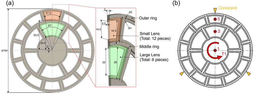
Figure 1. The simulation model: (a) Lens Frame Model; (b) Loads Position.
2.3 Loads and boundary conditions
This lens frame was installed in a sleeve device. There was an interference fit between the sleeve and the shaft hole of the lens frame, and other parts fixed both end-faces. Therefore, in the software, a fixed-constraint boundary condition was set for the outermost circumference of the part. Spacecraft need to withstand complex working conditions such as impact loads during the launch phase, dynamic loads generated by micrometeoroid impacts and attitude adjustments during in-orbit operation. During the simulation. Two significant types of load cases were set in the simulation. The first type of load case was to simulate the situation where an object hit the part, generating an impact force that could damage the part. In this case, there were three situations: (1) The load was applied at the center of the part (Position 1); (2) The load was applied on the large lens, and then transferred to the frame through the large lens (Position 2); (3) The load was applied on the small lens, and then transferred to the frame through the small lens (Position 3). The load magnitudes were 200 N, 400 N, 600 N, and 800 N, respectively, which covered the typical extreme values of mechanical loads that the spacecraft might encounter during takeoff and on-orbit operation. During the simulation, the lens was simplified as a rigid component, and the mechanical transmission relationship between the lens and the frame was simulated through the connector function in the software. When a load was applied to the lens, this setup could equivalently simulate the uniform pressure distribution generated by the lens on the groove of the frame, so as to simulate the extreme stress conditions borne by the frame. The other type of load case was to simulate the torque that might be generated during the installation process of the lens frame (Position T1). The torque magnitudes were 30 N m, 50 N m, and 100 N m, respectively, and they were applied to the solid disc at the center. The load application positions were shown in Figure 1b.
2.4 Material setting
Regarding the definition of the material properties of the model, the titanium alloy (Ti-6Al-4V) material was selected from the material library of the Altair software. It was an
2.5 Mesh and solver settings
In this simulation, the average mesh size was set to 0.3 mm. The mesh was automatically generated by the Inspire software, and the total number of meshes was 2.927 million. The OptiStruct solver built into the software was used for the solution. It was a high-end solver integrating structural analysis and optimization design. Based on the Finite Element Method (FEM), it discretized the continuum into a finite number of elements to solve the mechanical behavior of complex engineering structures accurately. For this simulation, the static-simulation module of the OptiStruct solver was used. Taking the nodal displacements as the fundamental unknowns, by establishing the element stiffness matrix and the global stiffness matrix, the Newton-Raphson iterative algorithm was used to handle nonlinear problems. The stiffness matrix was continuously updated through iterations to approach the exact solution gradually.
3 Results and discussion
3.1 Influence of different application positions of vertical loads
The simulation results when the load was applied at the center of the part were shown in Figures 2, 3. As seen from the displacement nephogram (Figure 2), the maximum displacement occurred at the exact center of the part. Under an 800 N load, the displacement was approximately 1.796 mm, and the displacement magnitude decreased diffusely towards the periphery. Under 200 N, 400 N, and 600 N loads, the maximum displacement degrees were 0.4490 mm, 0.8981 mm, and 1.347 mm, respectively. Significant stress concentrations in the von Mises equivalent stress nephogram (Figure 3) were evident within the lens-protecting fillets at the connections with the middle disk beam and the outermost ring beam. The maximum von Mises equivalent stresses under each load were 228.6 MPa, 457.2 MPa, 685.8 MPa, and 914.4 MPa, respectively. As the load gradually increased, stress concentration first occurred at the connection of the middle disk beam, followed by the lens-protecting fillets at the connection of the outer ring beam. When the load reached approximately 700 N, the stress concentration level reached the critical failure load of the titanium alloy material. Therefore, during the design of this part, special attention should be paid to the stress state and deformation conditions at the corners of the beam connections. Increasing the radius of fillets appropriately can help mitigate this issue.

Figure 2. Displacement nephogram for the load applied at the center of the part.
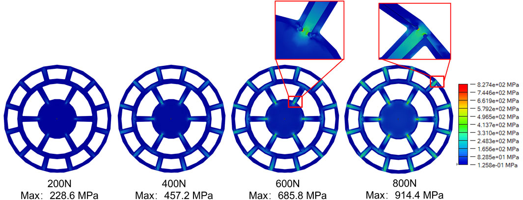
Figure 3. Von Mises equivalent stress nephogram for the load applied at the center of the part.
When the load was applied on the large lens, the deformation and stress conditions of the frame became severe (Figures 4, 5). Under an 800 N force, the maximum displacement reached 3.463 mm. Even under a low force of 200 N, the displacement was 0.8656 mm. This significant deformation may be caused by the thickness of the lens-fitting area of the part, which was only 0.5 mm, and it was simultaneously affected by the torque generated by the quasi-cantilever structure. The area with the maximum stress occurred at the connection of the outer ring beam, which was the connection end of the cantilever structure and had a relatively small cross-sectional area. The second highest stress area was at the connection of the central disk beam. However, as the load increased, obvious stress concentration gradually appeared at the middle ring’s connection, a phenomenon not observed in other load cases. Under a low load of 200 N, the maximum von Mises equivalent stress reached 640.3 MPa, and the yield strength of the material was reached at approximately 250 N. For every additional 200 N of load, the maximum von Mises equivalent stress caused by the structural deformation increased by about 640 MPa. However, when the load acted on the center of the small lens, this situation improved (Figures 6, 7). Both the displacement and von Mises equivalent stress were significantly reduced. From the displacement nephogram, it could be seen that the middle ring became the area with the maximum displacement. The displacements under each load were 0.2418 mm, 0.4837 mm, 0.7255 mm, and 0.9673 mm, respectively. As the load increased, the influence of the displacement change gradually affected the central position, while the impact on the outer ring changed little. This was because the fixed position of this part was the outer ring, and the central position was at the far end of the quasi-cantilever structure, making it more prone to displacement. Then, observing the von Mises equivalent stress nephogram (Figure 5), the stress concentration was located at the connection between the outer ring and the beam. Even under high loads, the connection between the middle ring and its connection beam was not significantly affected. The maximum von Mises equivalent stresses on the part were 375.2 MPa, 750.4 MPa, 1,126 MPa, and 1,501 MPa, respectively.
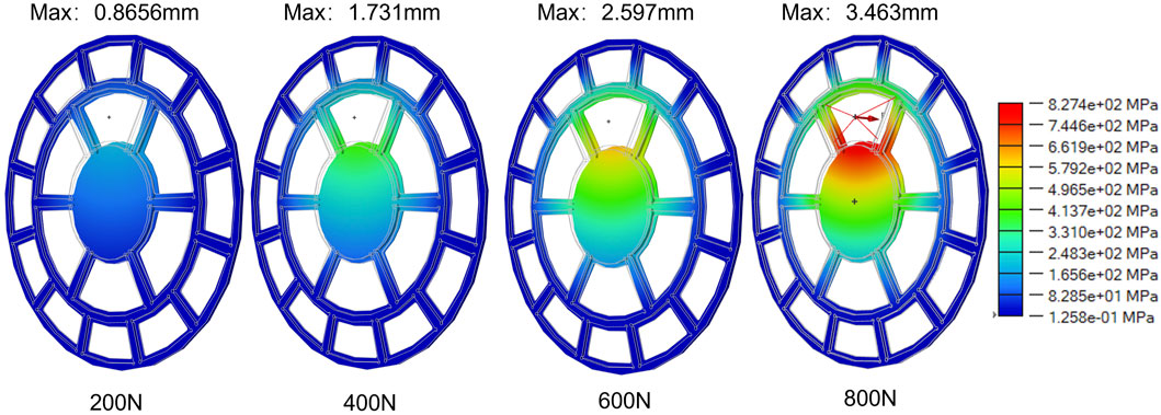
Figure 4. Displacement nephogram for load applied at the center of the large lens.
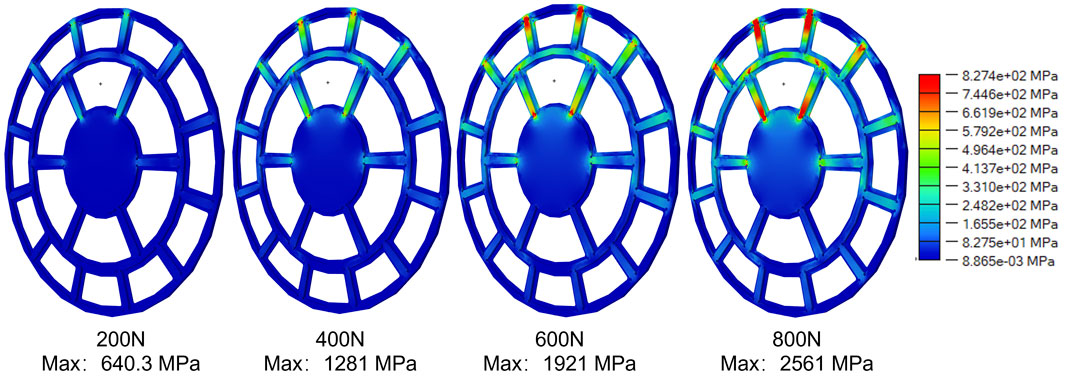
Figure 5. Von Mises equivalent stress nephogram for the load applied at the center of the large lens.
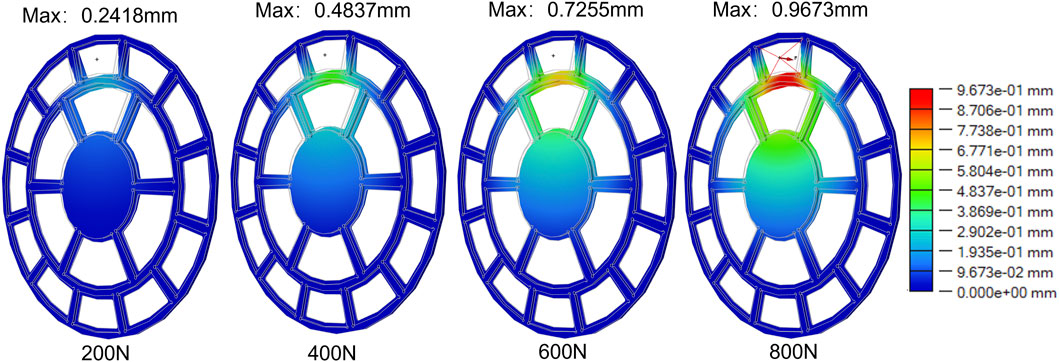
Figure 6. Displacement nephogram for load applied at the center of the small lens.
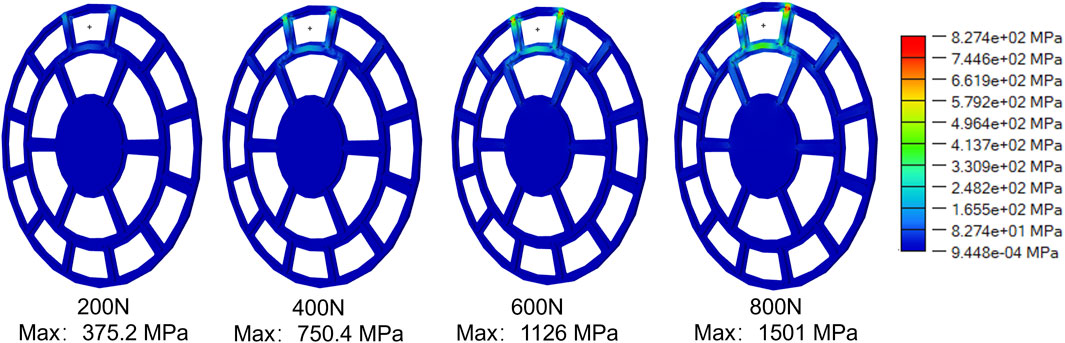
Figure 7. Von Mises equivalent stress nephogram for the load applied at the center of the small lens.
In summary, when this structure was subjected to vertical loads, the maximum load it could withstand was approximately 700 N. However, to ensure the structure’s safety, the load it endured during normal operation should not exceed 250 N. To improve the structure’s stability, it was necessary to further increase the fillet size at the beam connections and the cross-sectional area of the lens-protecting fillets.
3.2 Influence of torsional loads
The torsional load case was established to simulate the torque the part might experience during installation, aiming to evaluate the structural torsional resistance. As shown in Figure 8, under torsional loading, the overall displacement of the part remained extremely low. Although the central disk and rings were supported only by crossbeams, the maximum displacement reached just 0.2205 mm even under a high load of 100 N·m. Notably, the fillets designed at the crossbeam connections had a radius of only 1 mm, which inevitably caused significant stress concentration during torsion. As indicated by the von Mises equivalent stress nephogram (Figure 9), stress concentration first occurred at both ends of the middle long crossbeam. As the torque increased, the stress-concentrated region gradually expanded toward the crossbeam center, affecting its structural strength. Simulation results showed that when a torsional load of approximately 50 N·m was applied, the von Mises equivalent stress from stress concentration reached the yield stress threshold of the titanium alloy material.
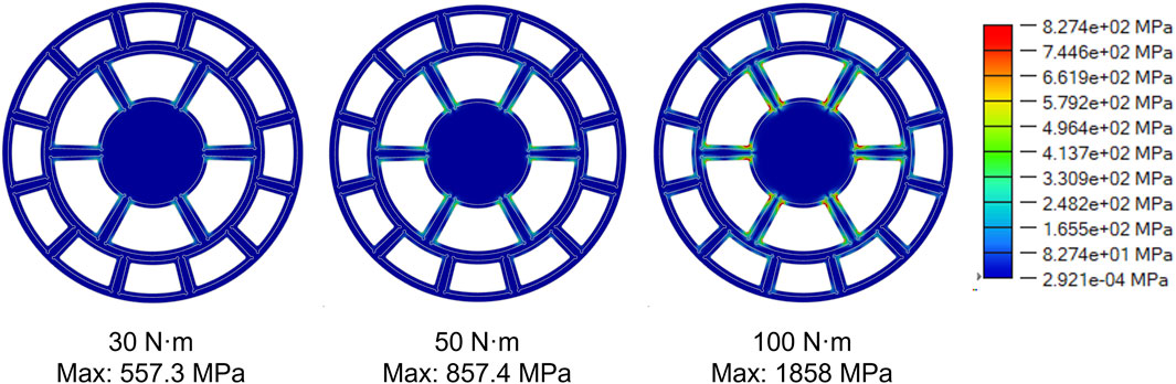
Figure 8. Displacement nephogram under torsional load.
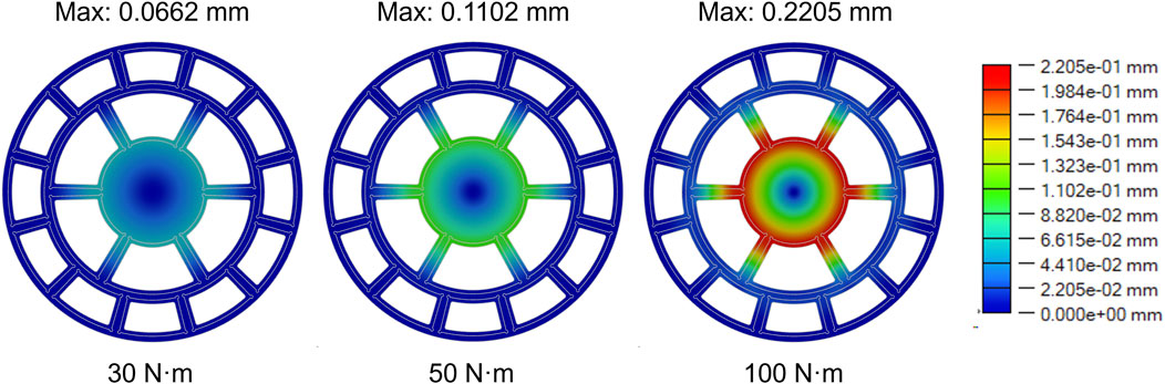
Figure 9. Von Mises equivalent stress nephogram under torsional load.
4 Conclusion
This study establishes a foundational simulation framework for analyzing the stress-strain performance of lightweight X-ray pulsar detection telescope frames, providing reference structural specifications and performance boundaries for the safety design of similar lightweight telescope frames. The main conclusions of the paper are as follows.
(1) Due to their minimal cross-sectional area, the most vulnerable locations of the designed lens frame are the lens-protecting fillets near the central disk, followed by those near the outermost ring. Without considering lens fracture, applying loads to the large lens causes the most severe deformation in the part, making it the most likely to induce failure.
(2) The part can withstand a maximum vertical load of approximately 700 N. However, the applied load should ideally be kept below 250 N to prevent cracking or failure during practical use.
(3) Although torsional loads do not cause significant displacement in the part, they induce substantial stress concentration at the crossbeam connections. The applied torque should not exceed 50 N m to avoid exceeding material limits.
(4) To enhance the part’s structural strength, the following recommendations are proposed: 1) Increase the overall thickness of the part, particularly at the lens frame area; 2) Enlarge the cross-sectional area of the connecting beams between rings; 3) Increase the radius of fillets at the corners of crossbeam connections.
The development of the telescope system requires collaborative efforts from multiple teams. Due to the confidentiality of relevant technical details, the current research mainly focuses on the structural design and theoretical performance analysis of the prototype. Future work will focus on integrating the mechanical properties of the selected lens material, manufacturing physical prototypes, and conducting matching mechanical performance tests and environmental adaptability assessments. This will improve the lens-frame coupling model and verify the stability of the overall structure. Complete physical prototype testing and space environmental adaptability assessments will be gradually carried out in subsequent studies. These efforts will help quantify the structural reliability under extreme conditions, support the iterative optimization of frame geometric parameters, and ultimately provide a solid theoretical and experimental basis for the engineering application of this lightweight frame in X-ray detection.
Data availability statement
The raw data supporting the conclusions of this article will be made available by the authors, without undue reservation.
Author contributions
QZ: Validation, Writing – review and editing, Investigation, Writing – original draft, Funding acquisition. ZH: Methodology, Formal Analysis, Writing – original draft, Software, Data curation. BX: Project administration, Resources, Conceptualization, Writing – review and editing. YL: Conceptualization, Investigation, Writing – review and editing. JL: Methodology, Writing – review and editing, Visualization. HZ: Conceptualization, Validation, Writing – review and editing. CY: Writing – review and editing, Investigation, Validation. LZ: Formal Analysis, Supervision, Writing – review and editing, Funding acquisition, Software.
Funding
The author(s) declare that financial support was received for the research and/or publication of this article. This work was supported by the National Major Scientific Research Instrument Development Project [42327802]. Thank you to the Shenzhen Science and Technology Innovation Commission for providing the General Project of the Stable Support Program for Higher Education Institutions (Category B) [No. 20231122155706001].
Conflict of interest
The authors declare that the research was conducted in the absence of any commercial or financial relationships that could be construed as a potential conflict of interest.
Generative AI statement
The author(s) declare that no Generative AI was used in the creation of this manuscript.
Publisher’s note
All claims expressed in this article are solely those of the authors and do not necessarily represent those of their affiliated organizations, or those of the publisher, the editors and the reviewers. Any product that may be evaluated in this article, or claim that may be made by its manufacturer, is not guaranteed or endorsed by the publisher.
References
Allan, D. W. (1987). “Millisecond pulsar rivals best atomic clock stability,” in 41st annual symposium on frequency control, 2–11. doi:10.1109/FREQ.1987.200994
Belov, K., Branch, A., Broschart, S., Castillo-Rogez, J., Chien, S., Clare, L., et al. (2018). A space-based decametric wavelength radio telescope concept. Exp. Astron 46, 241–284. doi:10.1007/s10686-018-9601-6
P. Bely (2010). “The design and construction of large optical telescopes,” Softcover reprint of the original. 1st ed. 2003 edition (New York, NY: Springer).
Chen, Z., Fang, C., Wang, Z., Yan, C., and Wang, Z. (2023). The influence of on-orbit micro-vibration on space gravitational wave detection. Photonics 10, 908. doi:10.3390/photonics10080908
Ebizuka, N., Dai, Y., Eto, H., Lin, W., Ebisuzaki, T., Omori, H., et al. (2003). in Development of SiC ultra light mirror for large space telescope and for extremely huge ground-based telescope. Editors E. Atad-Ettedgui, and S. D. ’ Odorico (Waikoloa, United States), 329. doi:10.1117/12.457408
García-Pérez, A., Fernández-Soler, A., Morgante, G., Pérez-Álvarez, J., Alonso, G., García-Moreno, L., et al. (2024). Temperature mapping methods for thermoelastic analyses of the ARIEL spacecraft payload module. Acta Astronaut. 223, 77–97. doi:10.1016/j.actaastro.2024.07.009
He, Y., Liang, Y., Wang, S., and Gao, W. (2024). Microstructural design and analysis of composite with a near-zero expansion coefficient (in Chinese). Electromech. Eng. 40, 1–5. doi:10.19659/j.issn.1008-5300.2024.05.001
Kotani, M., Imai, T., Katayama, H., Yui, Y., Tange, Y., Kaneda, H., et al. (2013). Quality evaluation of spaceborne SiC mirrors (I): analytical examination of the effects on mirror accuracy by variation in the thermal expansion property of the mirror surface. Appl. Opt. 52, 4797–4805. doi:10.1364/AO.52.004797
Lorimer, D. R., and Kramer, M. (2004). Handbook of pulsar astronomy. 1st edition. Cambridge: Cambridge University Press.
Lyne, A., and Graham-Smith, F. (2012). Pulsar astronomy. 4th Edn. Cambridge: Cambridge University Press. doi:10.1017/CBO9780511844584
Mathew, J., Prakash, A., Sarpotdar, M., Sreejith, A. G., Nirmal, K., Ambily, S., et al. (2017). Prospect for UV observations from the moon. II. Instrumental design of an ultraviolet imager LUCI. Astrophys. Space Sci. 362, 37. doi:10.1007/s10509-017-3010-6
Matsakis, D. N., Taylor, J. H., and Eubanks, T. M. (1997). A statistic for describing pulsar and clock stabilities. Astronomy Astrophysics 326, 924–928.
McElwain, M. W., Feinberg, L. D., Perrin, M. D., Clampin, M., Mountain, C. M., Lallo, M. D., et al. (2023). The james webb space telescope mission: optical telescope element design, development, and performance. PASP 135, 058001. doi:10.1088/1538-3873/acada0
O’Dell, C. R. (2009). Creation of the hubble space telescope. Exp. Astron 25, 261–272. doi:10.1007/s10686-008-9130-9
Rawley, L. A., Taylor, J. H., Davis, M. M., and Allan, D. W. (1987). Millisecond pulsar PSR 1937+21: a highly stable clock. Science 238, 761–765. doi:10.1126/science.238.4828.761
Rawley, L. A., Taylor, J. H., and Davis, M. M. (1988). Fundamental astrometry and millisecond pulsars. Astrophysical J. 326, 947. doi:10.1086/166153
Vinko, J., Szalai, T., and Konyves-Toth, R. (2023). The purport of space telescopes in supernova research. Universe 9, 244. doi:10.3390/universe9060244
Yu, F., and Xu, S. (2020). Flexible support structure based on spring principle for a high precision reflecting mirror. Optik 207, 164341. doi:10.1016/j.ijleo.2020.164341
Yu, B., Xu, Z., Mu, R., Wang, A., and Zhao, H. (2023). Design of large-scale space lattice structure with near-zero thermal expansion metamaterials. Aerospace 10, 294. doi:10.3390/aerospace10030294
Zhang, X., Nie, R., Chen, Y., and He, B. (2021). Deployable structures: structural design and static/dynamic analysis. J. Elast. 146, 199–235. doi:10.1007/s10659-021-09860-6
Zhong, C., Liu, J., Zhao, T., Schopphoven, T., Fu, J., Gasser, A., et al. (2020). Laser metal deposition of Ti6Al4V—a brief review. Appl. Sci. 10, 764. doi:10.3390/app10030764
Keywords: pulsar detection telescope, simulation analysis, structure design, load analysis, stress-strain
Citation: Zhou Q, Huang Z, Xu B, Lei Y, Lei J, Zhao H, Ye C and Zhu L (2025) Simulation analysis of stress-strain performance for a lightweight X-ray pulsar detection telescope frame structure. Front. Astron. Space Sci. 12:1624395. doi: 10.3389/fspas.2025.1624395
Received: 07 May 2025; Accepted: 30 July 2025;
Published: 12 August 2025.
Edited by:
Massimiliano Galeazzi, University of Miami, United StatesReviewed by:
Wenjie Zhao, Chinese Academy of Sciences (CAS), ChinaMaulik Shah, Charotar University of Science and Technology Chandubhai S Patel Institute of Technology, India
Copyright © 2025 Zhou, Huang, Xu, Lei, Lei, Zhao, Ye and Zhu. This is an open-access article distributed under the terms of the Creative Commons Attribution License (CC BY). The use, distribution or reproduction in other forums is permitted, provided the original author(s) and the copyright owner(s) are credited and that the original publication in this journal is cited, in accordance with accepted academic practice. No use, distribution or reproduction is permitted which does not comply with these terms.
*Correspondence: Likuan Zhu, emh1bGlrdWFuQHllYWgubmV0