Abstract
The cloud-based environments in which today's and future quantum computers will operate raise concerns about the security and privacy of user's intellectual property, whether code, or data, or both. Without dedicated security protections, quantum circuits submitted to cloud-based quantum computer providers could be accessed by the cloud provider, or malicious insiders working in the cloud provider's data centers. Furthermore, data embedded in these circuits can similarly be accessed as it is encoded using quantum gates inside the circuit. This study presents various hardware and architecture modifications that could be deployed in today's quantum computers, based on superconducting qubits, to protect both the code and data from potentially untrusted quantum computer providers or malicious insiders. Motivated by existing Trusted Execution Environments (TEEs) in classical computers, this study introduces the notion of Quantum Trusted Execution Environments (QTEEs) which leverage trusted hardware to hide or obfuscate quantum circuits executing on a remote, cloud-based quantum computer. This study presents multiple, different approaches to design of QTEEs and considers both hardware and architecture, as well as system software and operating system support necessary for realization of QTEEs. Overall, this study presents three hardware architectures, namely, QC-TEE, SoteriaQ, and CASQUE, that have been designed to protect users' circuits and data from potential threats originating from both malicious quantum computer cloud providers or insider attackers. This study further outlines a roadmap for other possible QTEEs that can be developed in the future, to account for different threat models or to support different types of quantum computer architectures.
1 Introduction
Noisy Intermediate-Scale Quantum (NISQ) computers are being rapidly developed, with machines over 100 qubits available today (Chow et al., 2021) and the industry projects 4, 000-qubit or larger devices before the end of the decade1. Many different types of quantum computers exist, with superconducting qubit quantum computers being one of the types available today to researchers and the public through cloud-based services. The superconducting qubit machines are developed by numerous companies, such as IBM2, Rigetti3, or Quantum Circuits, Inc.4. These machines implement quantum computing with superconducting electronic circuits which are operated at approximately 20 mK temperatures, by placing the quantum chips in dilution refrigerators.
Cloud-based services such as IBM Quantum (see text footnote 1), Amazon Braket5, and Azure Quantum (Hooyberghs and Hooyberghs, 2022) provide access to superconducting and other types of NISQ quantum computers remotely for users. Due to the expensive nature of the quantum computing equipment, we believe that the dominant means of accessing these computers will remain cloud-based. In the cloud setting, however, the cloud provider has full control over the quantum computers. Especially, they can have access to the circuits (and the resulting control pulses) that execute on the quantum computer. Given knowledge of the circuits (or equivalently of the control pulses, which can be reverse-engineered into the circuits), the cloud provider has full access to what the users are executing. The cloud-based model of quantum computing benefits users as it allows for on-demand access to quantum computation resources. But at the same time, it endangers the intellectual property and secrecy of users' algorithms and circuits executing on quantum computers—this necessitates development of security techniques to protect user's code and data from snooping by untrusted cloud providers, or malicious insiders in the remote cloud data centers.
To help protect from the untrusted quantum cloud providers or insider attackers, a number of researchers have so far focused on developing various kinds of Blind Quantum Computation (Childs, 2001; Broadbent et al., 2009; Aharonov et al., 2008; Morimae et al., 2011; Dunjko et al., 2012; Morimae and Fujii, 2012, 2013; Fitzsimons and Kashefi, 2017; Morimae, 2012; Sueki et al., 2013; Morimae and Koshiba, 2013; Giovannetti et al., 2013; Mantri et al., 2013; Morimae, 2014; Shan et al., 2021; Liu et al., 2020). Most of these works remain theoretical, due to the fact that most of the schemes require a local, trusted quantum computer and quantum networking to connect the local and cloud-based and quantum computers. Other approaches for protection from untrusted quantum computer cloud providers include Quantum Homomorphic Encryption (QHE) (Armknecht et al., 2015; Fontaine and Galand, 2007; Mahadev, 2020; Rivest et al., 1978; Tan et al., 2016; Liu et al., 2022; Zhang et al., 2021; Zeuner et al., 2021). However, the realization of fully secure QHE, as indicated by the “no-go theorem” (Fang and Liu, 2020), introduces exponential computational overhead. This impracticality arises, especially in the near term, as noisy quantum devices struggle to manage the substantial noise accumulation associated with such computations.
As an alternative approach to BQC or QHE, in this study, we propose new hardware architectures for the protection of quantum circuits from untrusted quantum computer cloud providers or from insider attackers. We show that trusted hardware can be incorporated into the quantum computer to help protect the user's circuits and data. We present different architectures for Quantum Trusted Execution Environments (QTEEs) which address various threat models.
1.1 Contributions
This journal paper combines and extends our existing research on QTEEs. It incorporates results and designs from our work on QC-TEE (Trochatos et al., 2023b) and CASQUE (Trochatos et al., 2024a), pre-print work on SoteriaQ (Trochatos et al., 2023a), trusted controller work presented at QCE (Trochatos et al., 2024b), and poster at QuantumOS workshop on the topic of software support for QTEEs (Trochatos and Szefer, 2024). It further introduces previously unpublished designs for system software and quantum operating system support needed for QTEEs. Combined, this journal paper contributes:
Design and evaluation of architecture for obfuscation of quantum circuit control pulses based on decoy control pulses, from QC-TEE and SoteriaQ work.
Design and evaluation of architecture for obfuscation of quantum circuit control pulses based on switching of pulses among different qubit and control channels, from CASQUE work.
Design for system software and quantum operating system support for QTEE.
Categorization of possible threat models and QTEE architectures (current and future) to address the different threat models.
2 Background
This section presents the basics of quantum computing. The fundamental unit of quantum computing is the quantum bit, or qubit, which represents the states in the process of quantum computing. Quantum bits can be measured, and the measurement is typically probabilistic. The quantum bits store quantum states, which are manipulated through quantum gates. Quantum bits, quantum gates that control them, and other operations such as measurement, together form the quantum circuit, which represents how these quantum bits are controlled by these quantum gates in order. Details are presented below.
2.1 Quantum bits
Quantum states are represented by the quantum bit or qubit. Qubit is the fundamental unit of quantum computing, analogous to the classical bit used in conventional computing. Like a bit, a qubit has two basis states, typically denoted in bra-ket notation as 0 and |1〉. One widely used representation is the matrix-vector representation, where the quantum states are represented by vectors. For example, the two basis states |0〉 and |1〉 are usually represented as follows:
However, unlike a classical bit, which is restricted to either 0 or 1, a qubit can exist in any linear combination of these two states, subject to the constraint that the total probability remains 1. This is often called superposition. Specifically, a qubit |ψ〉 can be expressed as follows:
where α and β are complex numbers that satisfy the normalization condition |α|2+|β|2 = 1.
In general, an n-qubit system has 2n basis states. The basis states span a 2n-dimensional space, ranging from |00…0〉 to |11…1〉. An arbitrary n-qubit state |ϕ〉 can be described as follows:
where the coefficients ai are complex numbers, and their magnitudes satisfy the normalization condition . i is the decimal number of a n-binary-digit number.
The above is also often called the pure state, and it cannot represent all quantum states. Quantum systems can also exist in mixed states, which represent a probabilistic combination of different quantum states. A mixed state occurs when, with probability pi, a system is in the quantum state |ψi〉. Such a probabilistic mixture is denoted as {(pi, |ψi〉)} and is described mathematically using the density matrix formalism. The density matrix ρ is defined as follows:
where , indicating that ρ is a matrix. This representation is useful for describing systems that are not in a definite quantum state but rather in a statistical mixture of possible states.
2.2 Measurement
Measurement in quantum computing is a crucial process that connects the quantum world to classical outcomes. Unlike classical computing, where the measurement result is definite, the measurement result of a quantum state is often probabilistic. According to Born's rule, for a state described as in Equation 3, the probability of measuring or observing |i〉 is given by
For the density matrix representation in Equation 4, the probability of measuring or observing |i〉 is given by
where |aji| is the component of |ψj〉 on |i〉.
Another difference from classical computing is that in classical computing, the state of a bit can be directly observed without affecting the system. However, measuring a qubit fundamentally alters its state. Prior to measurement, a qubit can exist in a superposition of multiple states, but once a measurement is made, the qubit collapses to one of its basis states, typically |0〉 or |1〉, with probabilities determined by the above equations.
One concrete and interesting example is quantum entanglement. For a 2-qubit Bell state in the form of:
according to Equation 5, the probabilities of individually measuring the first or the second qubit to get |0〉 or |1〉 are all . However, if both two qubits are measured, the probabilities of measuring |00〉 and |11〉 are both , and there will not be results of |01〉 and |10〉. This cannot be seen in classical computing. Consider two bits which can be probability in 0 and in 1. The measurement of them is independent, and thus, the result of one bit does not influence the result of the other bit, so there can be cases of 01 or 10.
Measurement not only extracts information but also causes an irreversible change in the quantum system, making it a unique and non-deterministic process compared to classical measurements. This interplay between quantum superposition, probability, and collapse is central to understanding how quantum algorithms operate and how quantum information is processed.
2.3 Quantum gates
In quantum computing, analogous to classical computing, the fundamental operations are quantum gates. Quantum gates are unitary operations that transform qubits, and quantum algorithms are constructed by applying a sequence of these gates to manipulate qubits into desired states.
A quantum gate U must satisfy the property of unitarity, meaning UU† = U†U = I, where U† is the conjugate transpose (or Hermitian adjoint) of U, and I is the identity matrix. When a quantum gate U operates on a qubit state |ψ〉, the transformation can be expressed as |ψ〉 → U|ψ〉. In matrix form, n-qubit quantum gates are represented by 2n×2n matrices that act on the vector representation of the qubit states.
For example, the Pauli-X gate, a single-qubit gate, performs a bit-flip operation, transforming |0〉 to |1〉 and |1〉 to |0〉. This gate is analogous to the classical NOT gate. Another crucial gate is the Controlled-NOT (CNOT) gate, also called the CX gate. The CNOT gate is a two-qubit gate where, if the control qubit is in the state |1〉, it applies a Pauli-X operation (bit-flip) to the target qubit; otherwise, it leaves the target qubit unchanged.
There are other quantum gates that do not have direct classical analogs. For instance, the RZ gate introduces a relative phase shift between the states |0〉 and |1〉 without changing their amplitudes. The SX gate performs a “half” of the Pauli-X gate's operation, and its function is unique to quantum computing without a clear classical counterpart.
The matrix representations of these gates, along with those of other quantum gates, are presented below. It should be noted that Qiskit's (Wille et al., 2019) qubit ordering convention is followed, where the leftmost qubit is the most significant, and the rightmost qubit is the least significant. As a result, the matrix representation of the CX gate may differ in other literature that uses different qubit ordering conventions:
2.4 Gate-level quantum circuit
Gate-level quantum circuits are the foundational model for executing quantum computations. Analogous to classical circuits that manipulate bits using logic gates such as AND, OR, and NOT, quantum circuits use quantum gates to manipulate qubits. Quantum circuit transforms the quantum state of qubits in a way that leverages principles such as superposition and entanglement, both of which have no counterpart in classical computing.
A gate-level quantum circuit is composed of a series of quantum gates applied sequentially or in parallel to one or more qubits. Each qubit is initialized in a well-defined quantum state, typically |0〉, and then undergoes transformations as the gates act on it. The result of these transformations defines the quantum algorithm being implemented. The final step in most quantum circuits is a measurement, where the state of the qubits is collapsed to classical bits, yielding the result of the computation.
Quantum circuits are typically represented diagrammatically, where time flows from left to right, and each line in the circuit diagram represents a qubit, with gates applied along the line to indicate operations on those qubits. An example of a gate-level circuit is shown in Figure 1.
Figure 1
2.5 Control pulses
Gate-level quantum circuits provide the structural basis for running quantum algorithms. They are easy to understand and are the abstract description of quantum algorithms, and thus, they are independent of the low-level hardware. Moving downward, the actual realization of qubits and quantum gates depends on the technology used. In superconducting qubit architectures, qubits are realized using Josephson junctions, while gates are realized using sets of analog RF control pulses which actuate the qubits or couplings between them to realize one-qubit and two-qubit gate operations, respectively.
A control pulse is generally characterized by five main parameters: the envelope, frequency, phase, duration, and amplitude. In the context of superconducting qubit control, the envelope determines the shape of the signal, which is generated using an arbitrary waveform generator (AWG). Envelopes are typically discretized into a series of time steps, where each element represents the amplitude at a particular time step. An alternative, more efficient approach involves the use of parameterized pulses. These pulses are defined by predefined shapes, requiring only a few parameters for storage. The frequency and phase define a periodic signal that modulates the envelope signal. In addition, duration specifies the length of the pulse, while the amplitude indicates the relative strength of the pulse. The combination of these components forms the control pulse that is sent to the qubit to perform the desired operation. There are separate control pulses for each qubit, as well as, control pulses used on “control” channels used to realize two-qubit operations. This precise manipulation of qubits using control pulses enables the implementation of quantum gates on superconducting qubit-based quantum computers. At the same time, the pulses totally define the operation of the quantum circuits being executed, thus knowing some or all of the pulse parameters can be used to reveal what circuit is being executed.
3 Cloud-based quantum computers
NISQ computers nowadays available from cloud-based services such as IBM Quantum vary in size from 5 qubits to 127 qubits. IBM also announced a 433 qubit machine in November 2022, as well as a projection for 4, 000-qubit or larger devices by the end of the decade (see text footnote 1). These machines are also available for researchers and the public. In addition to free access for research, pay-as-you-go access has been made available, with users paying 1.60 USD per runtime second with a credit card or IBM Cloud credits (see text footnote 2). As a reference, a 2-qubit Grover's search algorithm (Lavor et al., 2003) requires approximately 2μs per shot, with a usual 4, 096 shots per experiment the cost would be 0.013 USD.
Most algorithms require thousands of shots to execute. Each shot is one execution of the algorithm, and the outputs of all the shots are collected to compute the final output probabilities. The output probabilities can be the final answer of the algorithm, as is the case for Grover's search. Or the output probabilities can be used to drive optimization of the algorithm and its future iterations, as is the case for VQE (Peruzzo et al., 2014) and quantum machine learning (Biamonte et al., 2017). Any changes in the environment or operational errors of the NISQ computer will impact the output probabilities of the algorithms.
4 Threat models for QTEEs
The main objective of this study is to protect the users' quantum circuits from untrusted cloud-based quantum computing providers or malicious insiders. These possible attackers could try to attack different parts of the quantum computing system to extract information about users' circuits, so we consider two threat models for our design of QTEE architectures. Other threat models are possible but left for future work to explore them.
4.1 Entities in the threat models
In all the threat models in this study, we consider three entities: users, cloud provider (including malicious insiders), and quantum computer manufacturer. Users may have sensitive data and computation that they want to run on a quantum computer. Cloud provider manages the quantum computers. Quantum computer manufacturer is the entity who makes the quantum computers. Even if the cloud provider and quantum computer manufacturer have the same name, e.g., IBM, we assume they are separate business entities or divisions. This way, we separate security threats at run time (due to cloud provider) from supply chain and manufacturing security (due to quantum computer manufacturer). Many examples exist today of cloud providers who are not manufacturers, e.g., Amazon Braket (see text footnote 5) or Microsoft Azure Quantum (Hooyberghs and Hooyberghs, 2022).
4.2 Assumptions in the threat models
In this study, we assume honest-but-curious cloud provider, meaning that the cloud provider (or the insiders) honestly performs the requested operations, but at the same time may try to steal information. We thus consider side-channel type attacks but not fault-injection type attacks. We further focus on run-time attacks and leave consideration of supply chain or hardware modification attacks for future work.
4.3 Goals of the attackers
We consider two major adversarial objectives: First, the attackers may be interested in the data that the quantum program processes. Second, they want to learn the quantum algorithms itself. In particular, the algorithm running inside the quantum computer may be intellectual property that should be kept confidential, or the owner may not want to expose implementation details.
4.4 Means for attackers to collect information
We assume the attackers have various means of collecting information. First, the attacker can directly read the programs or code submitted to the cloud provider. This is the case today, there are no technological means in place for IBM, Amazon, or Microsoft, as cloud providers, to prevent them from seeing what code the users submit. This first scenario fits the untrusted cloud provider threat. Second, the attacker can collect traces of power, EM, or other information through side channels. Even if the attacker cannot directly read the code, the side channel information could be used to reverse engineer the program's control and data flow, allowing the attacker to deduce which kinds of algorithms are deployed and perhaps even the data. This second scenario fits the malicious insider threat—someone who may not have logical access to the user's submitted programs and data, but who has access to the equipment to perform side-channel attacks.
4.5 Threat model A: trusted QPU, untrusted controller
In this threat model, we assume the user is trusted as well as his or her compiler and the user is able to generate transpiled circuits that are sent to the cloud provider for execution. We assume that correct information about the properties of the quantum computers is provided to the user; thus, he or she can correctly transpile the circuits for the target quantum computer. We consider an untrusted quantum computer cloud provider that does not manipulate the transpiled circuit or the resulting control pulses or any classical information sent to the quantum computer for execution, but he or she can observe this information to try to learn user's circuits or data.
We assume that the QPU is trusted, in the case of superconducting qubit machines, this is the dilution refrigerator which contains all the qubits, similar to the processor chip being the trust boundary in classical trusted execution environments, such as Intel SGX (Costan and Devadas, 2016). Since the dilution refrigerator keeps an extremely low temperature and target pressure, any access or opening of the dilution refrigerator is easily detected. Furthermore, the intrusion will disturb temperature and pressure, effectively destroying the qubit state; thus, we assume the cloud provider cannot access the dilution refrigerator without destroying the quantum computation. We trust all the hardware (our additions as well as existing hardware) inside the dilution refrigerator to be correct, verified, and bug-free.
We assume the remaining components, namely, the controller and any cloud servers, are untrusted. This is where the attacks could be occurring. E.g., cloud provider can directly read the code submitted by the user (at the server) or a malicious insider can collect power traces from the controller to recover the control pulses executed (and thus the quantum gates, from which the circuit can be reverse engineered). Details of this threat model are shown in Figure 2a.
Figure 2
4.6 Threat model B: untrusted QPU, trusted controller
In this threat model, we also assume the user is trusted as well as his or her compiler and the user is able to generate transpiled circuits that are sent to the cloud provider for execution. We assume user has correct information about the properties of the quantum computers; thus, he or she can properly transpile the circuits for the target quantum computer. We assume again the quantum computer cloud provider that does not manipulate the transpiled circuits or the resulting control pulses or any classical information sent to the quantum computer for execution, but he or she can observe this information to try to learn user's circuits or data.
We assume the quantum computer controller is trusted. Since the controllers are based on classical CPUs and FPGAs, there are well-studied solutions, such as Intel SGX (Costan and Devadas, 2016), which can protect these components. E.g., any modification to data or code provided to Intel SGX enabled CPU will be detected by use of digital signatures, thwarting attacks at this level. Similar trusted execution environments for FPGAs have been similarly explored (Xia et al., 2021; Oh et al., 2021).
We assume the remaining components, namely, the cloud servers and the QPU are untrusted. This is where the attacks could occur. E.g., cloud provider can directly read the code submitted by the user (at the server) or the QPU could be manipulated to collect the information about quantum gates being executed. Details of this threat model are shown in Figure 2b.
5 Hardware architecture of SoteriaQ
In this section, we consider Threat Model A and leverage the trusted QPU to provide protections from the honest-but-curious untrusted quantum cloud provider or insiders. In this threat model, since the QPU is trusted, additional hardware can be introduced into the QPU to protect from the cloud providers. The first architecture for protection under this threat model is SoteriaQ. SoteriaQ targets superconducting qubit architectures. This section is based on our QC-TEE (Trochatos et al., 2023b) and SoteriaQ (Trochatos et al., 2023a) papers. The SoteriaQ work supersedes QC-TEE, and the two are together simply referred to as the SoteriaQ architecture.
To realize SoteriaQ, a number of hardware components need to be added to the internals of the dilution refrigerator. All components are available today and use very low power and area compared to existing quantum computer components. A block diagram of the major components and their connections is shown in Figure 3, and they are listed below.
Figure 3
5.1 Decryption engine and input bitmap memory
A Decryption Engine is used to decrypt the encrypted input bitmap and then store the decrypted input bitmap in the Input Bitmap Memory. The decryption engine works by first using public-key cryptography to establish a shared secret key (symmetric key) and then using symmetric-key cryptography to decrypt the input bitmap itself. Both the public- and private-key algorithms need to be post-quantum secure. All the decrypted secrets are assumed to be secure from probing while inside the quantum computer's fridge, following our threat model in Section 4.5.
5.2 Hardware security engine
Hardware Security Manager is used to send the bits of the decrypted input bitmap to the attenuation switches. Each drive and control channel is associated with one attenuation switch. In each 160dt time period, each of the drive and control channels for all the qubits is provided with one bit: 0 for no attenuation and 1 for attenuation.
The hardware security engine is a hardware implementation of a state machine that controls the attenuation switches (described in Section 5.3). After the decryption engine decrypts the ciphertext and stores the input bitmap in the input bitmap memory (shown in Figure 3), the hardware security engine is ready and circuit execution can start. As the RF control pulses arrive, the hardware security engine reads input bitmap bits from the memory and attenuates the randomized pulses.
After the start of a circuit, every 160dt the hardware security engine outputs one control bit, per drive or control channel. The bits come from the input bitmap memory and are used to instruct the switches to attenuate (if the bit is 1) or not (if the bit is 0) the pulses during that time period. Note that two-qubit gates are padded with delays to make their duration a multiple of 160dt, i.e., for two-qubit gates, multiple input bitmap bits will be used, since one bit is used per 160dt.
In addition to that, in case of randomize-output variant of the mixer algorithm (described in Algorithm 1), while executing the last layer of the circuit, which consists of X gates, the hardware security engine draws random bits from TRNG. The number of bits is equal to the number of qubits and attenuates if the signal on those qubits for which the generated TRNG bit is 0 and does not attenuate if the bit is 1. This is the opposite of input bitmap specification. However, with this specification, if the output bitmap bit is 1, that means X gate was applied and the state of qubit was flipped. Now, the 1 can be also sent to the user, who can xor the received measured bit ci with 1 to flip it. If no X gate was applied, the output bitmap bit is 0, and xor with 0 is equivalent to no operation.
Algorithm 1
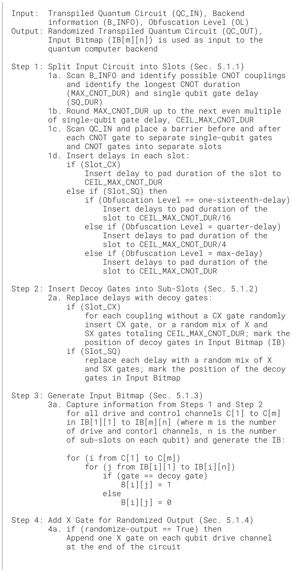
Decoy Pulse Insertion Algorithm. SlotCXis a slot that consists of at least one CNOTgate. SlotSQ is a slot that consists of only single-qubit gates.
5.3 Attenuation switches
One advantage of the superconducting qubit quantum computers leveraged in this study is the dilution refrigerator used to keep the qubits at cryogenic temperatures. The dilution refrigerator creates a natural boundary, where it is difficult to probe inside the refrigerator. This way, the outside of the refrigerator is considered the untrusted environment. This untrusted environment includes the cloud provider who controls the pulse generators and classical control equipment used to send RF pulses need to control superconducting qubits. At the same time, it is infeasible to add arbitrary equipment inside the refrigerator due to the limits on the cooling power. Naive TEE solutions, such as adding a signal generator inside the refrigerator, are not currently practical.
Attenuation switches are used to attenuate the decoy control pulses, which were added to confuse the potential attackers, and are not actually used for computation. The RF switches, each requires 1 bit of input to set if the switch should or should not attenuate the input RF signal during this time period.
Instead of adding excessive and likely unrealistic equipment inside the refrigerator, our proposed design leverages adding simple RF switches inside the refrigerator to attenuate the decoy control pulses sent to the quantum computer. The transpiled quantum program can include additional gates which should not be actually executed, but which are added to confuse the honest-but-curious quantum computer provider, who is observing the operation of the RF pulses. The proposed design can be realized by (1) inserting dummy control and drive pulses into transpiled program when user locally transpiles their quantum program, (2) encrypting classical ‘pulse mask' which is used to indicate which pulses should be executed and which should be attenuated, (3) send the pulse mask to the quantum computer, and (4) inside the boundary of the refrigerator decrypt the pulse mask and activate RF switches to attenuate control pulses according to the pulse mask.
The switches are passive elements, and they do not generate any control pulses themselves. Let us consider an single pole, double throw (SPDT) RF switch, whose single pole is connected to the input line of the fridge to receive the incoming RF signal. On the output side, one of the double throws is connected to the drive line that continues to the qubit device, while the other throw is terminated by a matched impedance. This way, the SPDT RF switch can either pass or isolate the drive pulses they use to operate the quantum processor, with its on–off state controlled by a DC gate voltage. In addition, they choose GaAs-based RF switches (such as CMD196C36) that can function at cryogenic temperatures, with a wide frequency range (DC-18GHz), low insertion loss (1.5dB), high isolation (46dB), and fast switching (2.5ns). Existing work has already tested RF switches capable of routing microwave signals at cryogenic temperatures (Pechal et al., 2016).
The control voltage of the switches is generated, achieved by the hardware security engine and the input bitmap. This “pulse mask” is encrypted by using quantum-safe encryption, and it is only decrypted inside the refrigerator. They propose to mount the switches (power consumption of only 1uW), the encryption and decryption engine (power consumption of only 20mW), as well as the simple control state machine, all on the high-temperature stage (such as the 4K stage) of the fridge, which provides ample cooling power (nearly 1W) to suppress the heating effect of the switch operations. The control logic and switches need to operate at a rate between 1 and 200MHz, which can be easily achieved. This is due to the fact that the single qubit gates in IBM machines each currently take 160dt, where 1dt = 0.222ns, and thus, each gate has to be attenuated (or not to be attenuated) at a rate of 35.5ns (= 160*0.222ns) or equivalently at a frequency of 28.5MHz. Due to the non-idealities of the on-state of the switch (such as the insertion loss or impedance mismatch), recalibrations of the phase and amplitudes of the single- and two-qubit gate pulses are required to optimize the gate infidelities.
5.4 Encryption engine and TRNG
SoteriaQ supports the option to randomize the circuit outputs, and this is achieved by conditionally executing X gates right before measurement operation at the end of the circuit. A TRNG controls which X gates are applied, and this information is also stored in the (encrypted) output bitmap sent to the user; many existing TRNG designs are available (Majzoobi et al., 2011), and design of TRNG is not the focus of this study.
The encryption engine is used if qubit flipping is enabled. The engine encrypts the output bitmap, so that the user can correctly interpret the qubit measurements. The engine uses symmetric-key encryption to encrypt the swapping bits with a randomly generated key and public key encryption to encrypt the symmetric key with the user's public key. Post-quantum secure encryption has to be used for the public key cryptography, while for symmetric key cryptography they use a hardware implementation of an AES-GCM (Koteshwara et al., 2017).
The encryption engine can be a hardware implementation of an AES-GCM (Koteshwara et al., 2017). It uses the same shared secret established as part of the decryption engine (described in Section 5.1) as a symmetric key to encrypt the TRNG output, i.e., the output bitmap, if randomize-output options is used. The client can later decrypt the encrypted output bitmap and conditionally apply logical NOT operations wherever the output bitmap indicates the corresponding bit had been flipped before measurement.
6 SoteriaQ obfuscation algorithm and software
In this section, we describe the algorithms for how control pulses are obfuscated with the addition of decoy pulses (in software, on user's end) and how later the decoy pulses are removed (in hardware, in the trusted fridge of the quantum computer). Our algorithm in software takes any transpiled quantum circuit as input, including circuits with custom gates, and performs a series of operations at the gate level to generate an obfuscated output circuit. The algorithmic description of the steps taken to insert the decoy control pulses is shown in Algorithm 1.
6.1 Circuit preparation
Our algorithm takes the input circuit already transpiled for the target backend and divides it into so-called slots. During processing of the circuit, barriers are inserted before and after CNOT gates to separate portions of the circuit with single qubit gates from ones with CNOT gates. Each barrier, thus, determines a start of a slot. The barriers are later removed and are only used during circuit preparation.
SlotCX is a slot that consists of at least one CNOT gate and optionally any single qubit gates on the other qubits where the CNOT gate is not connected. The duration of SlotCX slots is determined by choosing the longest CNOT gate duration out of all possible couplings on the backend and then rounding it up to be an even integer multiple of the single-gate duration. Having set the SlotCX duration this way, all SlotCX slots are checked and delays are added so that each SlotCX slot has the same length.
SlotSQ is a slot that consists of only single qubit gates and optionally any delays if required. The duration of these slots is determined at compile time and chosen based on the target security level. Currently, three duration periods are suggested: one-sixteenth-delay, quarter-delay, and max-delay. One-sixteenth-delay means the duration of SlotSQ is one sixteenth of the duration of SlotCX. Quarter-delay means the duration of SlotSQ is a quarter of the duration of SlotCX, and recall SlotCX slots are set to be of duration; this is even multiple of single-qubit gate duration. Max-delay means the duration of SlotSQ is equal to the duration of SlotCX.
The output of this circuit preparation step is a circuit that consists of multiple slots. The number of slots is determined by the depth of the circuit in terms of CNOT gates: whichever qubit has the most CNOT gates on it, which determines how many slots the circuit will be divided into. In our experience it is unlikely, but possible, that the number of single-qubit gates between any two CNOT gates can be more than what can fit in a duration of SlotCX. In such corner case, there will be two (or more) SlotSQ between consecutive SlotCX. In the usual case, however, SlotCX and SlotSQ occur in alternating order. Extra SlotCX and SlotSQ can also be added to increase confusion for the attacker, as well as to make it harder to guess the structure of the user's circuit.
6.2 Decoy gate insertion
Each slot is divided into equal-length sub-slots. The length of the sub-slot is equal to the duration of a single-qubit gate, 160dt on IBM quantum computers. Figure 4a earlier in the study shows the input circuit with the slots and sub-slots. Any sub-slots which are not occupied by a gate can be filled with decoy gates.
Figure 4
For each SlotCX in the circuit, on the unused qubits in that slot we either add a CNOT gate if CNOT coupling of the backend allows, or we add a random mix of X and SX gates; addition of other and custom gates is possible as well. Figure 4b shows in red color the addition of a decoy CNOT gate next to user's CNOT gate in a SlotCX. Note that the decoy CNOT gates are later attenuated, and the user's circuit's depth in terms of CNOT gates per qubit does not increase with our architecture.
For each SlotSQ, in addition to the existing single-qubit gates from the original circuit, a random mix of X and SX gates are added in each empty sub-slot; addition of other and custom gates is possible as well. Figure 4b shows in red color the addition of decoy single-qubit gates in a SlotSQ. The Rz gates from the original circuit are added to the slots but are not counted toward a sub-slot because the Rz gates are virtual.
Our design supports dynamical decoupling and the optimizations offered by the target platforms. We support a so-called decoy to identity gate conversion scheme. The output of our obfuscation scheme is a transpiled circuit which includes a number of decoy pulses. However, we observe that during insertion of decoy pulses, there will be one or many sequences of two X decoy gates or four SX decoy gates that are inserted. Two X gates in sequence or four SX gates in sequence each form an identity gate. These identity sequences can be allowed to execute by setting relevant configuration bits in the input bitmap to indicate they should not be attenuated. Furthermore, if any dynamical decoupling is added in software prior to our decoy gate insertion, it is also preserved.
6.3 Input bitmap generation
While constructing the quantum circuit with the added decoy gates, we keep note of each random single-qubit gate that is inserted. In each slot, for each qubit, we divide the slot into sub-slots, and each sub-slot is equal in duration to a single-qubit gate. Since one single-qubit gate fits in one sub-slot, we generate one binary bit per qubit per sub-slot to note if this is an actual gate, i.e., control pulse, or if this is a decoy pulse. The bit value 1 represents the algorithm has inserted a decoy gate as part of obfuscation in the corresponding sub-slot–this gate, i.e., pulse, will have to be later attenuated before it reaches the quantum computer's qubits, and thus, it does not actually perform any operation (Figure 4c). Meanwhile, the bit value 0 represents the gates that are part of the original input circuit from the original input and these should be executed, i.e., not attenuated. These bits are stored as the input bitmap. An example of the input bitmap was shown in Figure 4b earlier in the study.
6.4 Output randomization
An additional layer of X gates can be added at the end of the circuit to randomize the output (shown in Step 4 of Algorithm 1). The randomizing of the output happens inside the dilution refrigerator on the server end. This process is described in Section 7.
6.5 Circuit post-processing
At the end, the barriers are removed from the quantum circuit while the inserted gates remain. The resulting circuit is a valid circuit that can be executed on the target backend. However, unless the decoy gates are removed, i.e., attenuated, the result of the computation will be random. The purpose of SoteriaQ hardware, described later, is to attenuate the decoy gates, i.e., pulses, based on the (encrypted) input bitmap information, before these pulses actually reach qubits.
6.6 Circuit execution
After the algorithm finishes, the input bitmap has to be encrypted and signed by using quantum-safe cryptographic algorithms before transmission to the cloud provider. The encrypted digital input bitmap along with the plaintext circuit (that includes decoy gates) is sent to the cloud provider. The provider then schedules and executes the circuit on the target computer. The provider is untrusted (honest-but-curious) while the quantum computer fridge and hardware is trusted. In particular, the SoteriaQ hardware inside the trusted boundary of the fridge decrypts and validates the input bitmap and uses the information to determine which of the control pulses to attenuate. All the expensive signal generation logic in our design can be kept outside the fridge.
7 SoteriaQ deobfuscation and hardware
The SoteriaQ hardware and state machines effectively implement the inverse of the obfuscation. When the circuit is about to execute, the ciphertext (the encrypted input bitmap) is sent to the decryption engine (described in Section 5.1) inside the fridge. The AES-GCM module which is part of the decryption engine decrypts the ciphertext and re-generates the input bitmap containing information about which control pulses in which sub-slots should be attenuated. As shown in Figure 3, this input bitmap is stored in the input bitmap memory. After this, the hardware security manager and the signal/pulse generator are notified to start generating the RF signals involved in the quantum circuit (including the decoy pulses). The attenuation switches inside the fridge (shown in Figure 3) filter the unwanted random gates based on the control signals generated by the hardware security manager. We propose to achieve the synchronization between the hardware security manager and signal/pulse generator using handshake signals. Since the original quantum circuit is only deobfuscated inside the dilution refrigerator (which we consider a trusted boundary), we achieve the required secrecy between the client and server.
To help hide the output of the circuit, X gates are inserted at the end of the circuit, and during execution, the control logic generates corresponding X control pulses. However, when these X control pulses reach the quantum computer, SoteriaQ will randomly attenuate them; thus, the cloud provide does not actually know which of the pulses were executed, i.e., which output was flipped. In software, only X gates are inserted. The decision to attenuate them is performed randomly at runtime on SoteriaQ hardware by using the TRNG. The random bits used to specify whether to attenuate or not the final X gates are also encrypted and sent back to the user so he or she can know how to interpret the outputs.
8 SoteriaQ evaluation setup
To evaluate the fidelity overhead of SoteriaQ's hardware additions, we use the 7-qubit IBM machine (backend) ibm_perth to test small-scale benchmarks and 27-qubit ibm_algiers to test medium-scale benchmarks. We also use the Aer_Simulator with imported noise model from other different machines.
8.1 Benchmarks used
QASMBench Benchmark Suite version 1.4 (Li et al., 2020) was used in our study to analyze the impact of the SoteriaQ design on different circuits. We transpile each benchmark for the target backend. The transpiled code is then used as input to the obfuscation algorithm, which is described in Section 6. We test small-scale circuits on the free 7 qubit backend, as well as, we use the pay-as-you-27 qubits backend for medium-scale circuits. Overall, we test our design on 22 benchmarks. We keep the number of shots constant at 8, 192. For the simulator, we use the same set of benchmarks.
8.2 Obfuscation levels evaluated
We evaluated different configurations: baseline, one-sixteenth-delay, quarter-delay, max-delay; further for all the levels, except baseline, we analyze results with and without the randomize-output option. The baseline is simply the benchmark transpiled for the target backend without any of our modifications. The one-sixteenth-delay means the duration of SlotSQ is one sixteenth of the duration of SlotCX. The quarter-delay means the duration of SlotSQ is a quarter of the duration of SlotCX, and recall SlotCX slots are set to be of duration, which is even multiple of single-qubit gate duration. The max-delay means the duration of SlotSQ is equal to the duration of SlotCX. The randomize-output includes an additional layer of X gates before measurement to protect the output, and it can be applied to any of the obfuscation levels.
8.3 Variational distance
We measure the impact of our modifications on the circuits by using variational distance (VD). Informally, the variational distance of two output probability distributions is the measure of how one probability distribution is different from the other. In general, the total variation distance between P and Q is defined below. We compute variational distance between the circuit outputs generated without our modifications and the outputs generated for different obfuscation levels.
8.4 Circuit fidelity
We also measure fidelity (F) by performing state fidelity7 computations. The state fidelity computations use the density matrix of each state. Formally, the state fidelity F for density input states ρ1 and ρ2 is given by:
To show the worst possible effects due to SoteriaQ, we compute the fidelity between the best and worst possible configuration, i.e., between baseline (the unmodified benchmark) vs. the max-delay. This evaluation is discussed in greater detail in Section 9.4.
9 Evaluation of SoteriaQ
In this section, we present the evaluation of our design. Since we are not able to modify IBM Quantum computers to insert the RF switches and the SoteriaQ's logic, we focus on the evaluation of the expected impact of the changes on the fidelity of the circuits.
9.1 Impact of increased circuit duration
Our obfuscation technique works by adding decoy pulses and then attenuating them before actual execution. Once the decoy pulses are attenuated, they effectively become delays. In the presence of ideal RF switches, the circuit that is executed is the same as provided by the user but with extra delays (where the decoy pulses were). In the presence of imperfect RF switches, the locations where the pulses should be fully attenuated contain partial pulses, which increase noise and degrade the fidelity.
Manufacturer datasheets indicate that high-isolation RF switches can achieve extremely low leakage rates. For instance, Pasternack specifies that their cryogenic RF switches can achieve isolation levels of up to 90 dB at cryogenic temperatures. This isolation level translates to a leakage of approximately 10−9 of the original signal amplitude. We model imperfect switches as switches that attenuate the decoy pulses to 0.01% of the original amplitude, so they do not fully remove them as ideal switches would. Regardless of the switch attenuation effectiveness, by using our identity gate conversion technique, some of the lost fidelity can be recovered. The variational distance results for the worst case scenario, which is the max-delay obfuscation level, are shown in Table 1. The assumption of 0.01% amplitude transmission is conservative and ensures that our security analysis remains robust. Even if the actual leakage is lower, our security guarantees would still hold, and the fidelity impact would be less significant than anticipated.
Table 1
| Obfuscation level: | Max-delay | |
|---|---|---|
| w/o rand.-out. | w/ rand.-out. | |
| Avg. VD (perfect RF switches) | 0.2099 | 0.2453 |
| Avg. VD (imperfect RF switches) | 0.2652 | 0.2691 |
| Avg. VD (imperfect RF switches w/ identity gate conversion) | 0.1998 | 0.2188 |
Worst case variational distance (VD) for the QASMBench benchmarks considering: perfect RF switches, emulating imperfect RF switches which attenuate the decoy pulses to 0.01% amplitude, and considering our identity gate conversion scheme.
9.2 Sensitivity to quantum volume and noise
As quantum computers improve, we expect the impact of the noise to decrease. Indeed, we explored if and how quantum volume (QV) and noise model may impact the variational distance. Table 2 reports the average VD over the set of the QASMBench benchmarks, and we observe a lower average VD for higher quantum volume machines.
Table 2
| Obfuscation level: | Max-delay | |
|---|---|---|
| w/o rand.-out. | w/ rand.-out. | |
| Real IBM Perth (QV = 32) | 0.2099 | 0.2453 |
| Sim. IBM Perth (QV = 32) | 0.1461 | 0.1481 |
| Sim. IBM Mumbai (QV = 64) | 0.1653 | 0.1705 |
| Sim. IBM Cairo (QV = 128) | 0.1286 | 0.1299 |
Worst case variational distance (VD) for the QASMBench benchmarks for machines with different quantum volume (QV).
The VD is averaged over all the benchmarks and is reported for the max-delay obfuscation level, augmented with the randomize-output option. The data are for ideal RF switches.
9.3 Evaluation of circuit correctness
We evaluated the impact of the inserted decoy gates in the correctness of circuit outputs. In Table 3, we examined and show in detail the correctness of the output for 20 tested small-scale benchmarks and 2 medium-scale benchmarks for the three different configurations, with and without the randomize-output option considering imperfect switches that attenuate decoy gates to 0.01% of the original amplitude. We observe 100% correctness when we apply the one-sixteenth-delay configuration and nearly 90% correctness on average with max-delay. To emphasize, we observe correct output even for benchmarks with high depths, such as dnn and qaoa, which implies that our design can be scalable for circuits with more qubits and higher depths. Please note that for the evaluation of correctness, we compared the output of the baseline benchmark circuits without the addition of the decoy gates, with the output of modified benchmark circuits after inserting the decoy gates. If we are able to observe the true dominant state in both cases, we put a checkmark for this configuration. Although added decoy gates degrade the fidelity of the circuits, in all tested algorithms, we are able to observe correct outputs if the variational distance is less than 0.25.
Table 3
| Benchmark | Qubits | Gates | CX | Depth | Correctness | Fidelity | |||||
|---|---|---|---|---|---|---|---|---|---|---|---|
| One-sixteenth-delay | Quarter-delay | Max-delay | Max-delay | ||||||||
| w/o rand.-out. | w/ rand.-out. | w/o rand.-out. | w/ rand.-out. | w/o rand.-out. | w/ rand.-out. | w/ rand.-out. | |||||
| Deutsch | 2 | 5 | 1 | 5 | ✓ | ✓ | ✓ | ✓ | ✓ | ✓ | 0.978 |
| Iswap | 2 | 9 | 2 | 8 | ✓ | ✓ | ✓ | ✓ | ✓ | ✓ | 0.984 |
| Quantumwalks | 2 | 11 | 3 | 8 | ✓ | ✓ | ✓ | ✓ | ✓ | ✓ | 0.982 |
| Grover | 2 | 16 | 2 | 12 | ✓ | ✓ | ✓ | ✓ | ✓ | ✓ | 0.972 |
| dnn | 2 | 226 | 42 | 155 | ✓ | ✓ | ✓ | ✓ | ✓ | ✓ | 0.998 |
| Teleportation | 3 | 8 | 2 | 7 | ✓ | ✓ | ✓ | ✓ | ✓ | ✓ | 0.995 |
| qaoa | 3 | 15 | 6 | 12 | ✓ | ✓ | ✓ | ✓ | ✓ | ✓ | 0.994 |
| Toffoli | 3 | 18 | 6 | 13 | ✓ | ✓ | ✓ | ✓ | ✓ | ✓ | 0.991 |
| Linearsolver | 3 | 19 | 4 | 12 | ✓ | ✓ | ✓ | ✓ | ✓ | ✓ | 0.931 |
| Fredkin | 3 | 19 | 8 | 12 | ✓ | ✓ | ✓ | ✓ | ✓ | ✓ | 0.906 |
| Basis_change | 3 | 53 | 10 | 22 | ✓ | ✓ | 0.889 | ||||
| Adder | 4 | 23 | 10 | 12 | ✓ | ✓ | ✓ | ✓ | ✓ | ✓ | 0.825 |
| Bell | 4 | 33 | 7 | 14 | ✓ | ✓ | ✓ | ✓ | ✓ | ✓ | 0.987 |
| qft | 4 | 36 | 12 | 9 | ✓ | ✓ | ✓ | ✓ | ✓ | ✓ | 0.994 |
| Variational | 4 | 54 | 16 | 34 | ✓ | ✓ | 0.828 | ||||
| vqe | 4 | 89 | 9 | 28 | ✓ | ✓ | ✓ | ✓ | ✓ | ✓ | 0.995 |
| Basis_trotter | 4 | 1,626 | 582 | 815 | ✓ | ✓ | 0.401 | ||||
| Qec_en | 5 | 25 | 10 | 18 | ✓ | ✓ | ✓ | ✓ | ✓ | ✓ | 0.862 |
| Error_correctiond3 | 5 | 114 | 49 | 78 | ✓ | ✓ | ✓ | ✓ | ✓ | ✓ | 0.764 |
| qaoa | 6 | 270 | 54 | 110 | ✓ | ✓ | ✓ | ✓ | ✓ | ✓ | 0.945 |
| bv | 19 | 56 | 18 | 22 | ✓ | ✓ | ✓ | ✓ | ✓ | ✓ | 0.887 |
| Wstate | 27 | 157 | 52 | 55 | ✓ | ✓ | ✓ | ✓ | ✓ | ✓ | 0.835 |
Evaluation of correctness and fidelity for 22 QASMBench benchmarks (Li et al., 2020), assuming imperfect RF switches as simulated by gates representing decoy gates attenuated to 0.01% of the original amplitude of the gate on IBM ibm_perth quantum computer; number of Gates, CX, and Depth refer to pre-transpilation numbers.
Checkmarks indicate that we are to observe the true, i.e., correct, dominant state. The fidelity experiments are performed on Aer_Simulator with an imported noise model from the 127-qubit IBM Brisbane quantum computer. The evaluation is done for the worst case of max-delay configuration.
9.4 Evaluation of circuit fidelity
We also evaluated the state fidelity between the quantum states of each modified with the inserted delays benchmark, comparatively with the quantum states of the baseline unmodified benchmark, as shown in the last column of Table 3. We only performed experiments for the worst-case scenario (max-delay). We observe that, except one benchmark, the fidelity remains high. We observe basis_trotter to have the worst behavior regarding the fidelity loss. This is understandable, as the circuit uses 4 qubits but is quite deep, challenging the decoherence times of a NISQ device, even if we run it without applying our SoteriaQ scheme.
9.5 Evaluation of power requirements
Since we propose to add additional (minimal) hardware to the fridge, we consider the power consumption of these changes, since the hardware running our algorithms would be inside the dilution refrigerator that has limited cooling and power capabilities. For the public key cryptographic algorithm, we note that the existing work (Tasopoulos et al., 2023) shows that for CRYSTALS-Kyber with the highest security level, the Key Generation, Encapsulation, and Decapsulation consume 157mW, 160mW, and 162mW, respectively, on a Xilinx Artix 7 FPGA. For symmetric key cryptography, AES-GCM (Koteshwara et al., 2017) consumes 19mW for encryption/decryption on Altera Cyclone V FPGA. We note that while we were writing this study, no prior work on running cryptographic algorithms in cryogenic temperatures was documented in the literature to the best of our knowledge. However, we note that other applications, such as (Conway Lamb et al., 2016), have been successfully tested in cryogenic temperatures (4K). Since all cryptographic operations do not need to run at the same time, we estimate a needed budget of 180mW for our added hardware. Today, 1W cooling power at the 4K stage of the fridge should be easily achieved8; thus, our additions require only approximately 20% of the cooling budget, and this will become less with newer and better fridges.
9.6 Evaluation of area overhead
The main overhead of the scheme comes in terms of power, evaluated in above in Section 9.5, as well as physical overhead of the SoteriaQ's logic and RF switches. Considering XLD Blue Fors dilution refrigerator 9, the volume of the refrigerator with height of approximately 1, 481mm and radius of approximately 460mm is π × 4602×1, 481 = 984, 011, 944mm3. Bigger refrigerators will be needed for larger quantum computers, but taking this as a conservative estimate, our analysis shows the percentage of volume is taken by the added hardware for quantum computers with different qubit size. We observed that the overhead in all cases is 0.002% or less.
9.7 Scalability considerations
The proposed SoteriaQ can scale to handle large number of qubits. We note that publicly announced designs for large quantum computers are modular. For example, the forthcoming Flamingo processor (Gambetta, 2020) is projected to support 1,386 qubits, which will be located in three 462-qubit modules or chip. One SoteriaQ can be deployed per module or chip. Our analysis shows that in all cases, the expected power consumption of the SoteriaQ logic for different size quantum computers, from 27 to 1,386 qubits (Gambetta, 2020), will be nearly 180 mW. Note that larger quantum processors, such as Kookaburra, will be built from these smaller modules and would simply require a number of SoteriaQ hardware proportional to the number of the quantum computers.
10 Security analysis of SoteriaQ
To evaluate the security of our proposed scheme, we compute the total number of possible circuits that the obfuscated circuit could represent. This is the attack complexity from the perspective of the honest-but-curious cloud provider or insider attacker. In the computation, we take into account the following aspects: number of qubits (nqubits), number of CNOT gate slots (nSlotCX), number of single qubit gate slots (nSlotSQ), number of gates which fit in a slot SlotSQ on each qubit (nSubSlots), number of CNOT gates on different qubits in a SlotCX (nSubCXInSlotCX), number of single-qubit gates which fit on qubits not consisting CNOT gates in SlotCX (nSubSlotsInSlotCX). The number of combinations (Comb) that the malicious cloud provider must try to find the correct circuit executed inside the fridge is
Figure 5 shows how many circuit combinations an attacker (without any knowledge of the algorithm) needs to guess the circuit, versus the circuit duration increase for different obfuscation levels. In general, we observe the number of possible combinations an attacker would need to guess is significantly beyond 2256 security level, making it nearly impossible for attackers to deduce the true circuit. Based on Figure 5, we also observe that one-sixteenth-delay, the lowest obfuscation level, is sufficient to confuse the quantum cloud provider or insider attacker to be unable to apply brute force search to extract the circuit for most of the benchmarks. For example, for QAOA benchmark, which uses 6 qubits, 270 gates, and 84 CNOT gates (after transpilation), the attack complexity for max-delay is 212, 264; here, we assume nSubSlots = 18, nSlotSQ = 84 (between each CNOT gate slot there is one non-CNOT gate slot), and nqubits = 6; this is representative of the ibm_perth backend.
Figure 5
Our method can be also applied to hide the information of the victim circuits, even if attackers have some knowledge of the victim circuits. For some algorithms, the overall structure of the circuit, i.e., how gates are connected, may be fixed, while the specific configuration parameters of the circuit are encoded into parameters of the gates, e.g., rotational angles for VQE and QAOA. Both the algorithm and the specific configuration parameters need to be known to make them useful for attackers. Knowledge of the algorithm helps to decrease the attack complexity somewhat, but attackers still need to try to find the specific configuration parameters.
As an example, for QAOA, there is typically one rotational gate between each CNOT gate pair. Therefore, if the attacker knows the circuit to be a QAOA circuit, then he or she knows that only one rotational gate should be between each CNOT gate pair, and he or she can use that knowledge to eliminate some circuit combinations from their guesses. Since we break down the circuit into slots, this means for a single-qubit gate slot between two CNOT gate slots, the approximated lower bound of the number of choices for the attacker to guess the correct QAOA configuration is approximately , where ncp is the number of CNOT gate pairs in QAOA and nSubSlots is a number of gates which fit in a slot SlotSQ on each qubit.
We note that how the circuit is transpiled also affects the attack. Since not all qubits are connected on most quantum computers, swap operations may be inserted at transpliation time; swap operations are realized also using CNOT gates. The number of added swap operations is highly dependent on the circuit and the hardware, but an upper bound can be approximated. Suppose that there are nqubitsInBackend qubits in the quantum processor, then nqubitsInBackend−1 swap operations need to be added in the worst case to perform the CNOT gate between the two most far-apart qubits. Then, for ncpCNOT gate pairs, in the worst case in the transpiled circuit, there will be nc_switch = ncp×3 × (nqubitsInBackend−1) CNOT gates since one switch gate consists of three CNOT gates. The approximated upper bound of the number of choices for an attacker to guess the correct QAOA configuration will be .
For instance, the same example of QAOA benchmark uses 6 qubits, 270 gates, and 84 CNOT gates (after transpilation), if attacker knows this is QAOA benchmark, the attack complexity for max-delay is approximately 18798≈23330; here, we assume nc_switch = 42 × 3 × (7 − 1) = 756 for 7-qubit ibm_perth backend, for example, and nSubSlots = 18. Even with some knowledge, the attack complexity for the attacker is significantly beyond 2256 security level.
10.1 Additional possible attacks
If the cloud provider has more knowledge, like a list of possible circuits and their duration in time, they can leverage this information plus the real execution timing to perform a circuit identification attack. To protect from such timing side-channel attacks, the next step is to make the number of slots to be variable and not directly depend on the circuits. For example, a random number of extra SlotCX and SlotSQ can be added into the circuits, where each such slot is full of decoy control pulses. Users can add such random gates in software independently of our architecture.
There can also be power side-channel attacks on quantum computers, which have been proposed in concurrent work in Xu et al. (2023). However, the authors only assume the power can be measured from the drive equipment. If the on and off states of RF switches have an influence on the power and can be measured by malicious providers, then the providers may be able to recover the real circuits. Our work assumes the fridge forms a trust boundary and power attacks on equipment inside the fridge are out of scope.
11 CASQUE main features
In this section, we again consider Threat Model A and leverage the trusted QPU to provide protections from the honest-but-curious untrusted quantum cloud provider or insiders. In this threat model, since the QPU is trusted, additional hardware can again be introduced into the QPU to protect from the cloud providers. The second architecture for protection under this threat model is CASQUE. CASQUE targets superconducting qubit architectures. This section is based on our CASQUE (Trochatos et al., 2024a) paper.
11.1 Pulse switching
The key idea is pulse switching. Today, a cloud provider can directly see which pulses execute on which qubit. However, if new hardware is added to allow to switch any control pulse to any channel, then for each time period, there are , i.e., n choose k, possibilities that k pulses can execute on n qubits. Within limitations discussed later, after a circuit is transpiled, the control pulses can be re-arranged in ways in each time period and the re-arrangement information can be saved so that the pulses can be switched back during execution. The re-arrangement in software is a simple modification of digital data representing the circuit. In the hardware, the re-arrangement can be achieved by use of a Beneš Networks.
11.1.1 Single-qubit gates
Single qubit gates such as X and SX gates can be switched between any qubit channel. The amplitude of the pulses is different for different qubits; thus, if there is any switching, the amplitude has to be adjusted. To simplify the CASQUE design, we assume all single qubit pulses on all channels will be initially sent at maximum amplitude, and then, the trusted hardware attenuates them according to the target qubit. Since each incoming pulse regardless of the channel will have the same initial amplitude, the attenuation hardware does not need to know the initial amplitude or the channel, only the target channel.
11.1.2 Two-qubit gates
Two qubit gates such as CNOT gate cannot be switched between channels, at least in current IBM Quantum computer designs. The reason is that for different qubits and couplings, the exact pulses, not just their amplitudes, are different for different couplings. In base CASQUE, we assume that CNOT gates will not be switched. In CASQUE+, we discuss how to increase attack complexity by adding dummy qubits to the user's programs (as long as the quantum computer backend has sufficient physical qubits to accommodate the original qubits and the dummy qubits). Dummy qubits increase the number of possible locations for switching pulses, increasing n in the number of possible combinations. We further leverage the dummy qubits to enable the addition (and elimination) of dummy single-qubit gates, as well as two-qubit gates, such as CNOT gates. The dummy gates can be switched to the dummy qubits, effectively removing them—while the cloud provider does not know this is happening since they can only see the input circuit which includes the actual and dummy qubits and actual and dummy gates in the transpiled circuit specification.
11.2 Pulse protection map
We propose to save the re-arrangement information in a new data structure called Pulse Protection Map (PPM). The PPM can be viewed as a list containing switching information for each time period. The transpiled circuit can be easily modified to quantize the time into fixed time periods. For example, single-qubit gates on IBM Quantum today execute in 160dt time, while two-qubit gates have variable timing, but can be easily padded so that each two-qubit gate takes a duration that is a fixed multiple of 160dt. As a result, the PPM can be viewed as a list of control bits specifying the switching of pulses at each time period. The PPM needs to be encrypted so that the cloud provider does not access it. Inside the trusted hardware, the PPM can be decrypted. The decrypted control bits can be used directly to control the Beneš Network, and no real-time computation is needed–simply the control bits from PPM can be sent to the RF switches.
11.3 Attenuation and phase map
While control pulses can be easily switched between different channels, the same control pulse on different channels is slightly different. For example, the control pulse specifying X gate executing on qubit 0 may have a different amplitude than the control pulse specifying X gate executing on qubit 1. The phase of the pulses may also have to be adjusted. Furthermore, since we want to enable switching any pulse to any channel, the input pulse should have the maximum amplitude of all the channels. Thus, in the transpiled circuit, all the control pulses are at maximum amplitude. This means, regardless of the circuit, the input pulses going to the quantum computer will be at maximum amplitude, and the attenuation amount does not depend on the circuit. The attenuation amount and any phase change information can be stored in the Attenuation and Phase Map (APM). This is public information since the properties of the quantum computer, such as shapes and amplitudes of control pulses, are known. The APM can be stored on trusted hardware without any protection. The APM is used by our trusted CASQUE logic for amplitude and phase controller (APC) which we introduce into the dilution refrigerator.
11.4 Measurement obfuscation
After all the pulses are switched and the circuit finishes execution, there is a need to protect the measurements. To obfuscate the measurement results, the best approach is to randomly flip qubits before measurement by using X gates at the end of the circuit. However, gates cannot be simply “added” to the circuit in the dilution refrigerator. As an alternative, we assume the user transpiles his or her circuit with a layer of X gates at the end of the circuit, on half of the qubits used by the circuit qubits. During execution of the circuit, each X gate will be randomly switched to a different channel. Half of the qubits will not have X gate applied and their output is not flipped, while the other half will have the X gate applied and the output will be flipped. Assuming there are n qubits used, then there are possibilities for which qubits are flipped and which are not.
The switching of the final gates can be further determined at run-time, so for each shot, different qubits have their output flipped. To support this, TRNG can be used to generate randomness to determine which qubits to flip. This information about which X gates actually, i.e., which qubits were flipped, needs to be encrypted and sent back to the user so he or she can recover the correct outputs. We note that, as a side benefit, the addition of X before measurements may also help to reduce measurement errors (Tannu and Qureshi, 2019).
12 Software overview of CASQUE
We summarize the software steps required by CASQUE below, and we show them schematically in Figure 6.
Pad each CNOT gate with delays such that all CNOT gates with their associated padding take the same amount of time, and the duration including padding should be a fixed multiple of single-qubit gate duration.
Add padding between other gates if necessary to “line up” all the gates so that each gate starts at a time that is a multiple of single-qubit gate duration.
Increase the amplitude of each control pulse to the maximum amplitude needed by any channel.
For each time period, randomly switch the pulses between channels and add a layer of gates for flipping the output.
Save the switching information in the pulse protection map (PPM).
Encrypt PPM with the cryptographic key associated with the trusted CASQUE hardware inside the target.
Figure 6
The transpiled circuit (with all the modifications and with pulses switched between channels) is sent to the cloud provider, along with the encrypted PPM.
13 Hardware architecture of CASQUE
On the hardware end, the pulses need to be switched to the correct channels and possibly have their amplitude or phase adjusted. We assume the control pulses are correctly generated by the cloud provider, based on the user's transpiled circuit that they received. The untrusted cloud provider who we assume can passively try to spy on the information should not learn details of the circuit since they do not know how the pulses are switched and on which qubits they actually execute. The encrypted Pulse Protection Map (PPM) cannot be read by the cloud provider who does not have the decryption keys. However, the encrypted PPM is sent to the hardware before the circuit executes so that the trusted CASQUE Logic hardware can decrypt the PPM and send the control bits to the switches and amplitude and phase control. Compared to an unmodified quantum computer, a number of operations are performed on the control pulses which are input to the dilution refrigerator.
For each time period, based on the control bits from the PPM, the incoming pulses need to be switched to the correct channels; at each time period, the control bits are loaded into the Beneš Network to re-configure the routing of the incoming signals.
After the pulses pass the Beneš Network, they pass through amplitude and phase control; the APM specifies the attenuation and any phase shifting needed.
Finally, the control pulses are now sent to the mixers so that the incoming control signals can be mixed with the carrier signal at the frequency matching the channel.
For the output protection, at runtime, TRNG generates random bits used to determine how the final X gates will be switched, and this information is also encrypted and sent back to the user.
Switching control pulses requires more than just redirecting the control signals to different qubits. We need to consider other features of the control signals, such as the frequency or amplitude of the signals.
13.1 Pulse switching with Beneš network
Swapping of the control pulses between qubits and couplings can be realized by a Beneš network. A Beneš network can be used to switch signals between N inputs and N outputs, where any rearrangement of the inputs can be achieved without blocking. Beneš network of N inputs has 2 × log2(N)−1 stages, each containing N/2 two-by-two crossbar switches, and uses a total of N×log2(N)−N/2 two-by-two crossbar switches. For specifying switching, rather than specify for each qubit or coupling channel its target channel, we can instead directly provide control bits for each switch in the Beneš network at each time period. Recall that all gates in transpiled circuit are padded to that they each start at a time that is multiple of single-qubit duration. In effect, the circuits are quantized into fixed time periods. In each time period, N×log2(N)−N/2 bits are needed (i.e., one bit per switch to determine whether the switch should exchange its inputs, or let them pass unchanged).
The Beneš network's switches can be realized with standard RF switches. For example, the CMD272P310 is a low loss broadband positive control double-pole, double-throw (DPDT) transfer switch. The CMD272P3 covers DC to 10GHz and offers a low insertion loss of 1.6dB and high isolation of 43dB at 5GHz, which is the target frequency for many superconducting qubit quantum computers. The CMD272P3 operates using complementary control voltage logic lines of 0/+5V that can be easily generated by the control logic by converting typical single-ended outputs to differential pair outputs.
13.2 Frequency adjustment
In a superconducting qubit quantum computer, each qubit has a target frequency. Pulses generated for one qubit will not work on another if the frequency is incorrect. Figure 7 shows a schematic of a typical superconducting quantum computer showing arbitrary waveform generators (AWGs) with local oscillators (LOs) and mixers used to mix the I,Q pulses onto the target qubit's or coupling's frequency. The AWGs, LOs, and mixers are located outside the dilution refrigerator.
Figure 7
In CASQUE, the Beneš network can switch pulses but cannot adjust the frequency. Furthermore, we do not want to introduce any high-power equipment, such as signal generators, into the dilution refrigerator. A solution we propose for CASQUE is to move the mixers into the dilution refrigerator. The I and Q pulses are at the same frequency for all qubits, and it is only the frequency of the LO that changes for each qubit. Thus, the I and Q pulses can be sent through the switching network to switch the gates. Once the pulses are switched, they can be mixed with the LO signal.
13.3 Amplitude and phase adjustment
One of the main differences between the control pulses, in addition to the frequency, is the amplitude of the pulse. As discussed before, in CASQUE, all pulses are sent at the highest amplitude and then attenuated. The amplitude adjustment can be achieved with a voltage-controlled attenuator, for example, F2258NLGK8 from Renesas11. The example attenuator works in range up to 6GHz, with 1.4dB insertion loss and the control voltage can be from 0V to 3.6V. To generate the attenuation control voltage from digital information, a digital-to-analog converter is needed. Assuming 10 bits of resolution for the digital-to-analog, we can control the amplitude with resolution of over 0.001%. Detailed analysis of the type of the needed attenuation levels, and any residual impact of the attenuation on the control signals, is left for future work.
The phase of the control pulses also affects their operation. The phase information is stored in I and Q signals. If needed, the phase may have to be modified before the I and Q signals reach the mixers. Phase adjustment can be achieved with a phase shifter, for example, HMC649A from Analog Devices12. The example phase shifter works in 3 GHz to 6 GHz frequency range, with 8 dB insertion loss, and has a resolution of 6 bits, corresponding to phase adjust resolution of 5.625 degrees.
13.4 Combined hardware modifications
Figure 7 shows the combined modifications to the quantum computer hardware that CASQUE introduces. The additions inside the dilution refrigerator include the CASQUE logic, switching network, APC, and mixers. These are the trusted components. Furthermore, the CASQUE logic is made of one or more decryption tiles and engines discussed later to support various sizes of switching networks (and the number of control bits they require). The only modification to the untrusted hardware outside the dilution refrigerator is the removal of the mixers, which are now moved inside the fridge.
13.5 PPM and APM data size and bandwidth
The Beneš network requires N×log2(N)−N/2 control bits for each time period to allow for arbitrary switching of N channels. Furthermore, 10 × N control bits are needed for the amplitude control on N channels, and 6 × N control bits may be needed for phase adjustment.
The control bits for Beneš network are stored in PPM, and at each time period, the Beneš network requires N×log2(N)−N/2 bits need to be provided from the PPM to switch the switches. Meanwhile, control data related to amplitude and phase is stored in the APM. These control bits from APM only need to be provided before the circuit starts to execute. At each time period, for each channel, it is only needed to specify the type of gate, so the appropriate APM data can be used to adjust the amplitudes, for example. In IBM Quantum, there are X, SX, and CX basis gates that use real control pulses; thus, 2 × N = log2(3) × N control bits are needed for each time period, in addition to the switching bits. The time period corresponding to the duration of single-qubit gates is today 160 dt in IBM quantum computers, which is equivalent to 35.5 ns. This corresponds to a frequency of 28.5 MHz which the switching network control bits need to be provided.
13.6 Security-performance tradeoff with tiled switching network design
According to recent IBM roadmaps, large quantum computer systems will be built from smaller quantum computers or quantum computer chips on the order of 1, 000 qubits, such as the 1, 386-qubit Kookaburra quantum processing unit that can be replicated multiple times to build a larger computer. In a basic approach, CASQUE hardware can be instantiated for each quantum processing unit. Multiple CASQUE hardware can work in parallel, each with its associated quantum processing unit. While approximately 75 GB/s bandwidth between each CASQUE logic and its associated switching network is high, it is within reach of today's electronics (e.g., DDR5 can provide 51 GB/s data bandwidth per module, or HBM can provide 256 GB/s data bandwidth). However, so many switches are not needed in practice. From a security perspective, if we consider even circuits with an order of 6 qubits and 100s of gates, our evaluation in Section 9 shows the complexity can be above 2256. Thus, if we only switch a few channels, the attack complexity is huge and there is no need to switch all the channels each time and the 75 GB/s bandwidth is unlikely to be actually needed, order or two smaller bandwidth could be sufficient when only smaller number of qubits are switches—while still having high security level.
13.6.1 Tiling of the switching network
N×N Beneš network is actually built from two N/2 × N/2 networks with added layers. As a result, it is simple to trade off the number of possible permutations vs. the number of control bits (and thus bandwidth) needed. Table 4 shows different sizes of networks and the associated number of permutations, needed control bits, and bandwidth. Based on the different sizes of the network, a different number of control bits are needed. We note that in our design of the decryption engine which decrypts the PPM, discussed next, we use the AES algorithm, which has a block size of 128 bits. Each decryption tile can provide 128 bits in a time period. Depending on the size of the switching network, multiple tiles can be used in parallel.
Table 4
| Size | Perm. | Ctrl. Bits | Bandwidth | Num. Dec. Tiles |
|---|---|---|---|---|
| 2 × 2 | 21 | 1 | 3.5 MB/s | 1 |
| 4 × 4 | ~24.5 | 6 | 21.1 MB/s | 1 |
| 8 × 8 | ~215.3 | 20 | 70.4 MB/s | 1 |
| 16 × 16 | ~244.3 | 56 | 197.2 MB/s | 1 |
| 32 × 32 | ~2117.6 | 144 | 507.0 MB/s | 2 |
| 64 × 64 | ~2296.0 | 352 | 1, 873.0 MB/s | 3 |
Number of control bits, number of possible permutations, and corresponding bandwidth for different sizes of Beneš network.
Bandwidth computation is based on the number of control bits that need to be provided in each 35.5ns time period.
13.7 CASQUE logic and decryption engine design
In this study, we also implement a hardware design for the decryption engine, which is a key part of the CASQUE logic. The decryption engine helps decrypt the encrypted PPM inside the trusted hardware. For our evaluation, we consider AES-GCM algorithm to encrypt the PPM on the user's end. We use an existing AES-GCM module (Käsper and Schwabe, 2009) which can perform both encryption and decryption and implement a wrapper consisting of a controller which helps in loading the encrypted PPM from the BRAM or DRAM, decrypt it, and write it back to the same memory location block by block. We name this module as decrypt_tile (shown in Figure 8). The decrypt_tile has the capability of generating parameterized output width for these decrypted PPM bits. Users can choose the width arbitrarily based on the bandwidth requirement. Furthermore, the decrypt_tile also supports a high-performance mode where multiple decrypt_tile could be stacked together to decrypt large PPMs efficiently. The key required by the AES-GCM module is established using a quantum-safe public key algorithm, e.g., Classic McEliece (Albrecht et al., 2020). In our hardware design, for the public key algorithm, we use the mceliece38864 decapsulation module described in Section 5.4 of (Che, 2022). Other quantum-safe algorithms could be used as well.
Figure 8
In addition to the decryption engine, to protect the output generated from the quantum computer (discussed in Section 11.4), we also implement a True Random Number Generator (TRNG). For the TRNG module, we use an existing SHAKE256 module (Che, 2022) and implement a wrapper around it to feed an arbitrary size seed [we assume that there is a random number generator (RNG) inside the trusted hardware boundary that provides uniformly distributed random bits to our module as an initial seed] and squeeze out the required number (N) of random bits (RB), where N is the number of qubits for the given quantum computer. As discussed in Section 11.4, based on these bits, an X gate is either applied or not on the output of the quantum circuit. The wrapper also facilitates the encryption of RB using the AES-GCM module from the decrypt_tile, which is sent to the user.
The TRNG module uses the SHAKE256 with the smallest performance parameter configuration, i.e., parallel_slices = 1 (described in Che, 2022). The top_module combines all other modules as shown in Figure 8. The hardware utilization of our CASQUE hardware module is as follows: 3,340 LUTs, 1,158 FFs, 10 BRAMs, and it operates at a frequency of 103 MHz when targeted to Xilinx Artix 7 xc7a100t. To handle a 1 MB PPM, our hardware module takes 7.7 ns. These results do not include the resources used for the public-key algorithm. We do not report the BRAM utilization required for the PPM storage. This is because the size of the PPM changes as per the target quantum computer and quantum circuit. For large quantum computers and large circuits, the size of the on-chip BRAM may not be enough for the PPM storage, in which case we could use off-chip storage units such as DRAM. Our CASQUE hardware design supports the usage of either of them. We also note that we chose to target a lightweight hardware implementation for this evaluation. However, the parameterizable capability of our design allows switching to a high-speed parallel implementation easily.
13.7.1 Serializer–deserializer for outputs
Although the operating frequency of the CASQUE hardware module is higher (103 MHz), the frequency at which the pulse switching happens is much slower (i.e., 28.5 MHz, as described in Section 13.5). One possible solution to tackle this is to run the complete design at the (slower) switching frequency, but the bandwidth requirement of the Beneš network may not be met. Consequently, we run our design at the fast frequency and use an asynchronous FIFO (ASYNC_FIFO) to handle the crossing clock domains. Figure 8 shows usage of two sets of ASYNC_FIFOs, one for switching network and the other to control the application of X gate on the output. From the (ASYNC_FIFO), the decrypted PPM output is then loaded into the serializer–deserializer to arrange bits as per required bandwidth. We note that we successfully conducted practical experiments by running our hardware design on Xilinx Artix 7 xc7a100t FPGA and interfacing them with the RF switches (described in Section 13.1). We simulate the quantum computer control pulses, going into the RF switches, using a lab signal generator; an oscilloscope is used to validate that the switches attenuate the pulses when needed.
14 CASQUE evaluation setup
Our evaluation focuses on fidelity evaluation using variational distance (VD), as well as computation of complexity of how many circuit the attacker would have to try based on the obfuscation provided by the switching of the pulses. We use selected QASMBench benchmarks (Li et al., 2022) for the evaluation. Fidelity evaluation is done on the 7-qubits real IBM Perth quantum machine.
15 Fidelity evaluation of CASQUE
Assuming ideal operation of the switches and other added components, we focus on the impact of added delays due to “lining up” of gates done as part of CASQUE software steps. When CNOT gates are padded with delays to have fixed duration, we observe that with more delays, the variational distance increases, i.e., the fidelity decreases. For this reason, we measure the variational distance (VD) between each of the eight selected benchmarks and the unmodified benchmark from the QASMBench benchmarks suite. Informally, the variational distance of two output probability distributions is the measure of how one probability distribution is different from the other. In general, the total variation distance between P and Q is defined as follows: .
The impact of the extended duration of the selected benchmarks is presented in Table 5.
Table 5
| Benchmark | Qubits | Gates | CNOT | VD |
|---|---|---|---|---|
| Wstate | 3 | 30 | 9 | 0.126 |
| Basis_change | 3 | 53 | 10 | 0.116 |
| Variational | 4 | 54 | 16 | 0.080 |
| vqe | 4 | 89 | 9 | 0.195 |
| qec_en | 5 | 25 | 10 | 0.642 |
| Error_correctiond3 | 5 | 114 | 49 | 0.184 |
| Simon | 6 | 44 | 14 | 0.195 |
| qaoa | 6 | 270 | 54 | 0.203 |
Variational distance (VD) metric for selected QASMBench benchmarks (Li et al., 2022).
The Qubits, Gates (single-qubit gates), and CNOT numbers are pre-transpilation.
16 Security analysis of CASQUE
In the computation of the security level and the security analysis, we take into account the following aspects: number of qubits (nqubits), total number of single-qubit slots (p), number of single-qubit gate pulses in each slot (msi), total number of CNOT slots (q), number of single-qubit slots within duration of a CNOT slot (r), number of CNOT gate pulses we have in each CNOT slot (cj), and number of single-qubit gate pulses in each slot within a CNOT slot (mcj, k):
In the above equation, we use notation to represent n choose k computation. In our implementation, each CNOT gate slot is padded with delays such that all CNOT gates within the circuit take the same duration of time (equal to the duration of the longest CNOT gate on any of the coupling in the target quantum computer). The CNOT gate duration of time including padding is set to be a multiple of the single-qubit gate slot duration, currently 160dt. Since all CNOT gate slots are of the same duration, regardless which CNOT slot j is considered, the number of single-qubit gate slots that fit within the CNOT slot is the same and equal to r, as result r depends on the quantum computer backend which determines the duration of CNOT gates. Meanwhile, p, q, msi, mcj, k, and cj depend on the user's circuit, its structure, and the gates used. nqubits depends on the number of qubits used by the user's circuit but clearly cannot be larger than the number of qubits available on the target quantum computer. The approximate attack complexity on selected bencharks is shown in Table 6. The table also shows the complexity for CASQUE+ extended architecture, discussed next.
Table 6
| Benchmark | Qubits | Gates | CNOT | Complexity | |||
|---|---|---|---|---|---|---|---|
| 0 dummy qubits | w/ 2 dummy qubits | w/ 4 dummy qubits | w/ 8 dummy qubits | ||||
| (CASQUE) | (CASQUE+) | (CASQUE+) | (CASQUE+) | ||||
| Wstate | 3 | 30 | 9 | 28 | 215 | 219 | 225 |
| Basis_change | 3 | 53 | 10 | 243 | 266 | 280 | 2100 |
| Variational | 4 | 54 | 16 | 220 | 226 | 230 | 236 |
| vqe | 4 | 89 | 9 | 245 | 264 | 277 | 295 |
| qec_en | 5 | 25 | 10 | 217 | 222 | 226 | 232 |
| Error_correctiond3 | 5 | 114 | 49 | 2103 | 2132 | 2155 | 2191 |
| Simon | 6 | 44 | 14 | 220 | 225 | 228 | 233 |
| qaoa | 6 | 270 | 54 | 2268 | 2324 | 2365 | 2428 |
Approximate attack complexity on selected QASMBench benchmarks (Li et al., 2022).
Complexity calculated for zero, two, four, and eight number of added dummy qubits. The Qubits, Gates (single-qubit gates), and CNOT gates numbers are pre-transpilation.
17 CASQUE+ architecture
Our proposed CASQUE provides very good protection at a very high obfuscation level. However, we observed that a novel application of the switches can be realized if we assume that additional dummy qubits can be added to the user's circuit. Specifically, if dummy qubits (qubits not otherwise used by the original circuit) are added to the design, then it is possible to switch control pulses from the other qubits to the dummy qubits. Pulses switched to the dummy qubits do not affect nor perform any useful computation, and thus, they are effectively eliminated from the circuit. Furthermore, pulses can be added to the dummy qubits, and pulses can be switched among the dummy qubits, which also does not affect the actual computation.
17.1 Increasing obfuscation with added dummy qubits and dummy gates
Adding dummy qubits and dummy gates increases the number of possibilities for switching the gates–increasing the complexity for the attacker. Considering our prior Equation 1, adding dummy qubits increases nqubits. Adding dummy single-qubit gates increases msi and mcj, k. Adding two-qubit gates increases cj. However, the complexity increases further as in Equation 1 and baseline CASQUE design we do not alter the two-qubit CNOT gates. Now, with dummy qubits, we can add dummy two-qubit gates on original qubits and then switch them to the dummy qubits to eliminate them. As a result, the attacker (cloud provider) no longer is certain that a CNOT gate will execute (as it did in CASQUE). Rather, each CNOT could be a real gate that executes or could be a gate that is eliminated (by switching it to a dummy qubit) before execution. The updated complexity for the number of possible circuits that the untrusted cloud provider would have to guess from is
17.2 Preventing dummy qubit detection
Although the attacker does not know which are the dummy qubits from the input circuit, they could use the circuit structure to guess the dummy qubits. First, if the circuit can be partitioned into two disjoint circuits not connected by a two-qubit gate, then the attacker could easily say that one of the two circuits is made up of the dummy qubits. Thus, we must ensure that there is at least one dummy two-qubit gate that connects one of the original qubits with one of the dummy qubits. Second, if there is no measurement on a qubit, it can be identified as an ancillary qubit (actually used by the circuit, but not measured) or as the dummy qubit. Thus, we must ensure there is a measurement gate on all qubits, so that all qubits look like they are part of the circuit, even if the measurement will be discarded by the user.
17.3 Switching of multi-qubit gates
The current design of CASQUE does not switch multi-qubit gates due to the complexity of the waveform of the multi-qubit gates. However, this can also be done with enough knowledge of the waveform of the multi-qubit gates. For example, if the CNOT gates on different qubit pairs have the same waveform, then this can be easily done with the same scheme as in CASQUE. Nevertheless, the current design of the CNOT gate on the IBM cloud introduces different duration and pulse patterns, which may require additional hardware, such as the hardware to change the duration of pulses. The study of switching multi-qubit gates is left for future work, but we acknowledge that switching CNOT gates would further increase attack complexity.
17.4 Operation of CASQUE+
Figure 9 shows schematically the steps of extending the user's circuit with CASQUE+ protections. We assume that the input is the CASQUE protected circuit. The steps are done on top of, or in addition to, the protection applied by CASQUE. The steps to add dummy qubits and dummy gates are as follows:
Add dummy qubits to the circuit.
Randomly add two-qubit gates in CNOT gate slots, ensure that at least in one slot one of the added gates uses both real and dummy qubits.
Randomly add single qubit gates.
Add measurement gates on all qubits.
Update pulse protection map.
Figure 9
17.5 Analysis of increased complexity
Based on Table 6, we can achieve higher complexity by adding additional dummy qubits to the circuits. We tested for two, four, and eight additional dummy qubits for every application. We observe the highest complexity for the 6-qubit benchmark qaoa, as this benchmark has the highest number of gates and CNOT gates among all the tested benchmarks. We acknowledge that in CASQUE+ architecture, some extra qubits for the machine are occupied and prevented from being used by other applications to run in parallel; however, we consider this to be a minor issue in larger quantum machines.
18 Comparison of SoteriaQ and CASQUE
SoteriaQ and CASQUE take fundamentally different approaches to securing quantum computations, each with its own strengths and trade-offs in terms of performance and protection. In general, CASQUE is expected to introduce less delay compared to SoteriaQ. This is primarily because CASQUE avoids extensive use of decoy operations. Instead, it relies on rearranging the quantum channels effectively by permuting the mapping of logical operations onto physical qubits and thus to achieve obfuscation. By not requiring uniform-duration slots or time-padding, CASQUE keeps the circuit shallower and the execution faster. This makes it especially appealing for platforms with tight coherence budgets or when minimizing latency is a priority. SoteriaQ, on the other hand, is designed with a stronger emphasis on security. It introduces a greater number of decoy gates and employs slot equalization to conceal timing information, aiming to neutralize an adversary's ability to infer circuit structure through side-channel analysis. While this approach results in increased latency, fidelity loss, and potentially greater resource usage, it offers a higher level of protection, particularly against adversaries capable of monitoring fine-grained execution characteristics. Please note that both mitigation schemes are application-agnostic. Ultimately, the two architectures represent different points in the design space. CASQUE favors efficiency and is well-suited for scenarios where performance is a key constraint. SoteriaQ accepts additional overhead to provide stronger obfuscation, making it a better fit for threat models where more sophisticated attacks are anticipated.
19 Hardware architecture of a trusted controller
In this mitigation strategy, we aim to analyze what protections a trusted quantum computer controller could give users from honest-but-curious cloud providers who want to learn what quantum programs or data, i.e., quantum circuits or algorithms, are being executed by the user. We assume the cloud provider has access to all the information and electronics, including the interior of the dilution refrigerator (in case of superconducting quantum machines). The threat model can be applied to both superconducting and non-superconducting quantum machines. We assume the honest-but-curious provider can observe any communication (digital and analog) but does not tamper with it (such tampering can be detected by checking the quality of the solution). Thus, the goal is to protect from passive attacks, such as information leakage. Active attacks such as fault injection are orthogonal and future work.
19.1 Abstracted view of a quantum computer controller
We present an abstracted view of the quantum computer controller and make the assumption that the quantum controller, which converts the digital control pulses to analog RF pulses, to be trusted. We develop a simple abstraction of a quantum computer controller: A classical processing unit (CPU/FPGA), which is required to manage and orchestrate the quantum operations and a digital-to-analog and analog-to-digital converter unit (DAC/ADC), converts the digital signals into analog signals suitable for manipulating the qubits, and also converts analog signals back to digital ones that can be processed on the controller. A typical schematic of our proposed controller architecture is shown in Figure 10. Considering the two units: CPU/FPGA and DAC/ADC, there are four possible combinations:
Figure 10
19.2 Untrusted CPU/FPGA and untrusted DAC/ADC
If both the CPU/FPGA and DAC/ADC in a quantum computing system are untrusted, clearly the units cannot be leveraged to provide protection mechanisms. This is equivalent to today's cloud-based quantum computers, where there are no added security features nor trust in the controller.
19.3 Untrusted CPU/FPGA and trusted DAC/ADC
An untrusted CPU/FPGA is not able to provide any security features. However, a trusted DAC/ADC, on the other hand, could be leveraged to protect the circuits during the digital to analog, or analog to digital conversion. As DAC/ADC is involved in conversion of signals, we assume it has no computation power on its own, so it may not be able to add, remove, or modify the quantum circuits. However, in theory, it is possible for a trusted DAC/ADC to manipulate its operation as it generates analog signals (DAC), or when it recovers digital signals from analog inputs (ADC).
Hiding power signatures: The power consumption of electronic devices, including DAC/ADC, can exhibit characteristic patterns during different operations. By intentionally introducing variations in power consumption that are independent of the actual digital data (for DAC) or analog signal (for ADC), the DAC/ADC unit may attempt to make it more difficult for an attacker to analyze the power side-channel and extract sensitive information.
Injecting noise: A trusted DAC/ADC unit could dynamically adjust output signal (for DAC) to create noise in the RF lines and mitigate EM based side channels, or it could manipulate digital data (for ADC) to confuse the cloud provider about what is actually read from the quantum computer signals.
19.4 Trusted CPU/FPGA and untrusted DAC/ADC
A trusted CPU/FPGA can be leveraged to add, remove, or modify the quantum gates in a circuit before it is sent to the quantum computer. It can also manipulate the received measurements before they are passed onto the rest of the cloud computing infrastructure. Importantly, trusted CPU/FPGA can be used to decrypt circuits received from users, and encrypt the results.
Adding circuit and its inverse: The trusted CPU/FPGA could insert quantum gates and their inverses (Saki et al., 2021) into a circuit. The trusted CPU/FPGA could in this way obfuscate the structure of the circuit. The output analog signals observed by the cloud provider would correspond to the obfuscated circuit.
Swapping qubits: Quantum swapping operations allow the rearrangement of qubits (Trochatos et al., 2024a). The trusted CPU/FPGA could dynamically modify quantum circuits to swap qubits or channels. The resulting circuit executed on the quantum computer would have different qubit orders, adding some obfuscation.
Executing dummy shots: The trusted CPU/FPGA could execute dummy or decoy shots. These dummy shots would later have to be discarded. The cloud provider, not knowing which are right and which are wrong shots, would have more difficulty guessing what is the actual computation being done by the user.
19.5 Trusted CPU/FPGA and trusted DAC/ADC
Having both a trusted CPU/FPGA and a trusted DAC/ADC in a quantum computing system combines the benefits of both a trusted CPU/FPGA and a trusted DAC/ADC.
20 Design of QOS support for QTEEs
The deployment of the Quantum Computer Trusted Execution Environments (QC-TEEs) necessitates a Quantum Operating Systems (QOS) that can support QCTEE hardware and operation. In this section, we outline the mechanisms necessary for the secure loading of quantum circuits, the establishment of a trusted environment for their execution, and the return of computation results to users.
20.1 Existing QTEEs
Several QTEEs have already been proposed in the literature, which are briefly introduced below.
20.1.1 QC-TEE
The QC-TEE framework (Trochatos et al., 2023b) introduced the concept of adding obfuscation to quantum circuits. While digital control pulses of quantum circuits can be encrypted, they ultimately need to be converted to analog pulses for execution on quantum hardware, and analog pulses cannot be encrypted digitally. This leaves them vulnerable to potential spying and attacks by untrusted cloud providers. QC-TEE introduced hardware modifications to filter out dummy obfuscation pulses before they reach the qubits. Encrypted metadata allows QTEE hardware to distinguish between genuine and dummy obfuscation pulses.
20.1.2 SoteriaQ
Building on the QC-TEE (Trochatos et al., 2023b), the SoteriaQ framework (Trochatos et al., 2023a) detailed a comprehensive architecture for circuit obfuscation. As with QC-TEE, encrypted metadata helps the QTEE hardware identify dummy obfuscation pulses.
20.1.3 CASQUE
The CASQUE framework (Trochatos et al., 2024a) introduced a novel approach to obfuscation by swapping pulses between different control and drive channels. In the user's circuit, after transpilation, the control pulses are swapped between channels. CASQUE includes hardware modifications that allow these pulses to be redirected back to their correct channels before reaching the qubits. Encrypted metadata enables CASQUE hardware to determine the correct channel mapping.
20.2 Life cycle of quantum circuit in QTEE
Regardless of the QC-TEE type, the lifecycle of a circuit in a QTEE follows three phases: (I) secure loading of quantum circuits, (II) execution on the quantum computing hardware, and (III) transmission of computation results back to the users. Figure 11 outlines the life cycle of a quantum circuit as handled by QOS.
Figure 11
20.2.1 Phase I: secure loading of quantum circuits
On the user end, the quantum circuit is obfuscated according to the target QC-TEE, and encrypted metadata is attached to the circuit. The obfuscated circuit and encrypted metadata are securely sent to the cloud provider, by an encrypted network connection. Upon decryption of the network packets, the circuit and encrypted metadata needs to be safely stored by QOS while awaiting execution. The QOS needs to support classical, secure networking to receive users' circuits and their encrypted metadata. The QOS needs to track of the circuit and encrypted metadata once received. When storing them on the cloud, the circuit and encrypted metadata need to be associated with each other. Since the obfuscation method and encrypted metadata is specific to a particular quantum computer, the QOS scheduling also needs to be augmented to keep track of which quantum computer the circuit can execute on.
20.2.2 Phase II: secure execution of quantum circuits
When the circuit is ready to execute, the transpiled circuit is loaded onto the quantum controller, which, for example, in case of superconducting qubit quantum computer, generates the analog pulses that drive the qubits. In case of QC-TEE (Trochatos et al., 2023b), SoteriaQ (Trochatos et al., 2023a), and CASQUE (Trochatos et al., 2024a), these pulses contain some form of obfuscation. Thus, in parallel the encrypted metadata has to be sent to the quantum computer, so it can decrypt it and operate on the input pluses according to the metadata. For example, for Trochatos et al. (2023a), some pulses are attenuated based on the metadata, while for (Trochatos et al., 2024a), channels on which pulses are supposed to execute are swapped. The QOS needs to ensure that the obfuscated circuits of the user are loaded in parallel to the encrypted metadata on the target quantum computer.
20.2.3 Phase III: transmission of computation results back to the user
For each shot of a circuit, it is measured and results returned to the user. Both QC-TEE (Trochatos et al., 2023b) and SoteriaQ (Trochatos et al., 2023a) proposed to randomly insert X gates at the end of the circuit to randomize the output. In parallel, the modified quantum computer hardware generates (and encrypts) its own metadata that can be used by the users to know which qubits' outputs were flipped by the X, so the users can recover the correct output. To support these operations, the QOS needs to keep track of the (encrypted) output metadata and transmit it back to the user along with circuit outputs. The transmission back to the user should use secure, classical networking. The QOS needs to ensure that the circuit outputs and the output metadata are associated until they are returned to the user. The QOS needs to support classical, secure networking to send back users' results and their encrypted output metadata.
20.3 Analysis of QOS support for QTEE
The QOS modifications to support QTEE are minimal and can be realized with no overhead on the computation (beyond the overheads of the specific QTEE hardware). Scheduling will be impacted by the QTEEs need that the circuit protection is specific to each quantum computer (because of the unique cryptographic keys needed for the encrypted metadata). QOS scheduler cannot move a circuit to a different quantum computer since each circuit targets a specific backend. This is not a problem in the current NISQ era as all circuits are transpiled to a specific back end. But in error corrected quantum computers, where a circuit can execute on different quantum computer backends, this will be a new constraint that the QOS needs to manage.
21 Conclusion
This study has demonstrated a comprehensive approach to establishing Trusted Execution Environments (TEEs) for quantum computers, ensuring secure execution even in potentially untrusted quantum cloud environments. The proposed architectures tailored for superconducting quantum machines, including CASQUE and SoteriaQ, offer robust mechanisms for obfuscating quantum control pulses and measurements, thus significantly mitigating threats from side-channel attacks and malicious insiders. Through layered hardware and software protections, such as decoy pulse insertion, randomized output gates, and encrypted Pulse Protection Maps (PPM), the system effectively conceals sensitive quantum circuits and user data from unauthorized entities. We also explored architectures that minimize the trusted area and cover the non-superconducting quantum machines. In this direction, we proposed a hardware architecture for securing quantum computers with a trusted controller.
The results underscore the feasibility and scalability of the proposed solutions in quantum cloud infrastructure, with minimal performance overhead and security assurances surpassing conventional approaches. The use of trusted controllers opens avenues for extending this framework to diverse quantum architectures beyond superconducting qubits. Future research will aim to adapt these security measures to other quantum computing paradigms and integrate new advancements in TEE technology to support the growing quantum ecosystem.
Statements
Data availability statement
The original contributions presented in the study are included in the article/supplementary material, further inquiries can be directed to the corresponding author.
Author contributions
TT: Conceptualization, Data curation, Formal analysis, Funding acquisition, Investigation, Methodology, Project administration, Resources, Software, Supervision, Validation, Visualization, Writing – original draft, Writing – review & editing. CX: Conceptualization, Data curation, Formal analysis, Funding acquisition, Investigation, Methodology, Project administration, Resources, Software, Supervision, Validation, Visualization, Writing – original draft, Writing – review & editing. SD: Conceptualization, Data curation, Formal analysis, Funding acquisition, Investigation, Methodology, Project administration, Resources, Software, Supervision, Validation, Visualization, Writing – original draft, Writing – review & editing. YL: Conceptualization, Data curation, Formal analysis, Funding acquisition, Investigation, Methodology, Project administration, Resources, Software, Supervision, Validation, Visualization, Writing – original draft, Writing – review & editing. YD: Conceptualization, Data curation, Formal analysis, Funding acquisition, Investigation, Methodology, Project administration, Resources, Software, Supervision, Validation, Visualization, Writing – original draft, Writing – review & editing. JS: Conceptualization, Data curation, Formal analysis, Funding acquisition, Investigation, Methodology, Project administration, Resources, Software, Supervision, Validation, Visualization, Writing – original draft, Writing – review & editing.
Funding
The author(s) declare that financial support was received for the research and/or publication of this article. This study was supported in part through National Science Foundation grant no. 2312754, 2245344, and 2332406.
Conflict of interest
The authors declare that the research was conducted in the absence of any commercial or financial relationships that could be construed as a potential conflict of interest.
Generative AI statement
The author(s) declare that no Gen AI was used in the creation of this manuscript.
Publisher’s note
All claims expressed in this article are solely those of the authors and do not necessarily represent those of their affiliated organizations, or those of the publisher, the editors and the reviewers. Any product that may be evaluated in this article, or claim that may be made by its manufacturer, is not guaranteed or endorsed by the publisher.
Footnotes
1.^IBM'S target: a 4000-qubit processor by 2025. Available online at: https://spectrum.ieee.org/ibm-quantum-computer.
2.^IBM quantum. Available online at: https://quantum-computing.ibm.com/.
3.^Rigetti computing. Available online at: https://www.rigetti.com/.
4.^Quantum circuits. Available online at: https://quantumcircuits.com/.
5.^Amazon braket. Available online at: https://aws.amazon.com/braket/.
6.^Cmd196c3. Available online at: https://www.qorvo.com/products/d/da007444.
7.^https://docs.quantum.ibm.com/api/qiskit/0.19/qiskit.quantum_info.state_fidelity
8.^Oxford Instruments. Principles of dilution refrigeration.
9.^Bluefors. Cryogen-free XLDsl dilution refrigerator measurement system. bluefors.com. Available online at: https://bluefors.com/products/xldsl-dilution-refrigerator/ (accessed August 5, 2023).
10.^Qorvo. Cmd272p3 dpdt transfer switch documentation.
11.^Newark. f2258nlgk8 rf attenuator documentation.
12.^Analog. Hmc649a documentation.
References
1
AharonovD.Ben-OrM.EbanE. (2008). Interactive proofs for quantum computations. arXiv:1704.04487.
2
AlbrechtM. R.BernsteinD. J.ChouT.CidC.GilcherJ.LangeT.et al. (2020). Classic McEliece. Technical report, National Institute of Standards and Technology. Available online at: https://csrc.nist.gov/projects/post-quantum-cryptography/round-3-submissions.
3
ArmknechtF.BoydC.CarrC.GjøsteenK.JäschkeA.ReuterC. A.et al. (2015). A guide to fully homomorphic encryption. Cryptol. ePrint Archive.
4
BiamonteJ.WittekP.PancottiN.RebentrostP.WiebeN.LloydS. (2017). Quantum machine learning. Nature549, 195–202. 10.1038/nature23474
5
BroadbentA.FitzsimonsJ.KashefiE. (2009). “Universal blind quantum computation,” in 2009 50th Annual IEEE Symposium on Foundations of Computer Science, 517–526. 10.1109/FOCS.2009.36
6
ChenP.ChouT.DeshpandeS.LahrN.NiederhagenR.SzeferJ.et al. (2022). Complete and improved FPGA implementation of classic McEliece. Cryptology2022, 71–113. 10.46586/tches.v2022.i3.71-113
7
ChildsA. M. (2001). Secure assisted quantum computation. Quantum Inf. Comput. 5, 456–466. 10.26421/QIC5.6-4
8
ChowJ.DialO.GambettaJ. (2021). IBM quantum breaks the 100-qubit processor barrier. IBM Research Blog 2.
9
Conway LambI. D.CollessJ. I.HornibrookJ. M.PaukaS. J.WaddyS. J.FrechtlingM. K.et al. (2016). An FPGA-based instrumentation platform for use at deep cryogenic temperatures. Rev. Sci. Instr. 87:014701. 10.1063/1.4939094
10
CostanV.DevadasS. (2016). Intel SGX explained. Cryptol. ePrint Archive.
11
DunjkoV.KashefiE.LeverrierA. (2012). Blind quantum computing with weak coherent pulses. Phys. Rev. Lett. 108:200502. 10.1103/PhysRevLett.108.200502
12
FangK.LiuZ.-W. (2020). No-go theorems for quantum resource purification. Phys. Rev. Lett. 125:060405. 10.1103/PhysRevLett.125.060405
13
FitzsimonsJ. F.KashefiE. (2017). Unconditionally verifiable blind quantum computation. Phys. Rev. A96:5217. 10.1103/PhysRevA.96.012303
14
FontaineC.GalandF. (2007). A survey of homomorphic encryption for nonspecialists. EURASIP J. Inf. Secur. 2007, 1–10. 10.1155/2007/13801
15
GambettaJ. (2020). IBM'S roadmap for scaling quantum technology. IBM Research Blog (September 2020).
16
GiovannettiV.MacconeL.MorimaeT.RudolphT. G. (2013). Efficient universal blind quantum computation. Phys. Rev. Lett. 111:230501. 10.1103/PhysRevLett.111.230501
17
HooyberghsJ.HooyberghsJ. (2022). “Azure quantum,” in Introducing Microsoft Quantum Computing for Developers: Using the Quantum Development Kit and Q# (Berkeley, CA: Apress), 307–339. 10.1007/978-1-4842-7246-6_11
18
KäsperE.SchwabeP. (2009). “Faster and timing-attack resistant AES-GCM,” in International Workshop on Cryptographic Hardware and Embedded Systems (Springer), 1–17. 10.1007/978-3-642-04138-9_1
19
KoteshwaraS.DasA.ParhiK. K. (2017). “FPGA implementation and comparison of AES-GCM and deoxys authenticated encryption schemes,” in 2017 IEEE International Symposium on Circuits and Systems (ISCAS), 1–4. 10.1109/ISCAS.2017.8050315
20
LavorC.ManssurL.PortugalR. (2003). Grover's algorithm: quantum database search. arXiv preprint quant-ph/0301079.
21
LiA.SteinS.KrishnamoorthyS.AngJ. (2020). Qasmbench: a low-level QASM benchmark suite for NISQ evaluation and simulation. arXiv preprint arXiv:2005.13018.
22
LiA.SteinS.KrishnamoorthyS.AngJ. (2022). Qasmbench: a low-level quantum benchmark suite for NISQ evaluation and simulation. ACM Trans. Quant. Comput. 4, 1–26. 10.1145/3550488
23
LiuJ.LiQ.QuanJ.WangC.ShiJ.SituH. (2022). Efficient quantum homomorphic encryption scheme with flexible evaluators and its simulation. Designs, Codes Cryptogr. 90, 577–591. 10.1007/s10623-021-00993-2
24
LiuW.-J.ChenZ.-Y.LiuJ.-S.SuZ.-F.ChiL.-H. (2020). Full-blind delegating private quantum computation. arXiv preprint arXiv:2002.00464.
25
MahadevU. (2020). Classical homomorphic encryption for quantum circuits. SIAM J. Comput. 52, FOCS18–189. 10.1137/18M1231055
26
MajzoobiM.KoushanfarF.DevadasS. (2011). “FPGA-based true random number generation using circuit metastability with adaptive feedback control,” in Workshop on Cryptographic Hardware and Embedded Systems. 10.1007/978-3-642-23951-9_2
27
MantriA.Pé rez-DelgadoC. A.FitzsimonsJ. F. (2013). Optimal blind quantum computation. Phys. Rev. Lett. 111:230502. 10.1103/PhysRevLett.111.230502
28
MorimaeT. (2012). Continuous-variable blind quantum computation. Phys. Rev. Lett. 109:230502. 10.1103/PhysRevLett.109.230502
29
MorimaeT. (2014). Verification for measurement-only blind quantum computing. Phys. Rev. A89:060302. 10.1103/PhysRevA.89.060302
30
MorimaeT.DunjkoV.KashefiE. (2011). Ground state blind quantum computation on aklt state. Quant. Inf. Comput. 15, 200–234. 10.26421/QIC15.3-4-2
31
MorimaeT.FujiiK. (2012). Blind topological measurement-based quantum computation. Nat. Commun. 3:1036. 10.1038/ncomms2043
32
MorimaeT.FujiiK. (2013). Blind quantum computation protocol in which alice only makes measurements. Phys. Rev. A87:050301. 10.1103/PhysRevA.87.050301
33
MorimaeT.KoshibaT. (2013). Composable security of measuring-alice blind quantum computation. Available online at: https://arxiv.org/pdf/1306.2113.pdf
34
OhH.NamK.JeonS.ChoY.PaekY. (2021). Meetgo: a trusted execution environment for remote applications on fpga. IEEE Access9, 51313–51324. 10.1109/ACCESS.2021.3069223
35
PechalM.BesseJ.-C.MondalM.OppligerM.GasparinettiS.WallraffA. (2016). Superconducting switch for fast on-chip routing of quantum microwave fields. Phys. Rev. Appl. 6:024009. 10.1103/PhysRevApplied.6.024009
36
PeruzzoA.McCleanJ.ShadboltP.YungM.-H.ZhouX.-Q.LoveP. J.et al. (2014). A variational eigenvalue solver on a photonic quantum processor. Nat. Commun. 5:4213. 10.1038/ncomms5213
37
RivestR. L.AdlemanL.DertouzosM. L. (1978). On data banks and privacy homomorphisms. Found. Secure Comput. 4, 169–180.
38
SakiA. A.SureshA.TopalogluR. O.GhoshS. (2021). “Split compilation for security of quantum circuits,” in 2021 IEEE/ACM International Conference On Computer Aided Design (ICCAD), 1–7. 10.1109/ICCAD51958.2021.9643478
39
ShanR.-T.ChenX.YuanK.-G. (2021). Multi-party blind quantum computation protocol with mutual authentication in network. Sci. China Inf. Sci. 64:162302. 10.1007/s11432-020-2977-x
40
SuekiT.KoshibaT.MorimaeT. (2013). Ancilla-driven universal blind quantum computation. Phys. Rev. A87:060301. 10.1103/PhysRevA.87.060301
41
TanS.-H.KettlewellJ. A.OuyangY.ChenL.FitzsimonsJ. F. (2016). A quantum approach to homomorphic encryption. Sci. Rep. 6:33467. 10.1038/srep33467
42
TannuS. S.QureshiM. K. (2019). “Mitigating measurement errors in quantum computers by exploiting state-dependent bias,” in Proceedings of the 52nd Annual IEEE/ACM International Symposium on Microarchitecture, 279–290. 10.1145/3352460.3358265
43
TasopoulosG.DimopoulosC.FournarisA. P.ZhaoR. K.SakzadA.SteinfeldR. (2023). Energy consumption evaluation of post-quantum tls 1.3 for resource-constrained embedded devices. Cryptology ePrint Archive, Paper 2023/506. 10.1145/3587135.3592821
44
TrochatosT.DeshpandeS.XuC.LuY.DingY.SzeferJ. (2024a). “Dynamic pulse switching for protection of quantum computation on untrusted clouds,” in 2024 IEEE International Symposium on Hardware Oriented Security and Trust (HOST), 404–414. 10.1109/HOST55342.2024.10545385
45
TrochatosT.SzeferJ. (2024). Quantum operating system support for quantum trusted execution environments. arXiv:2410.08486.
46
TrochatosT.XuC.DeshpandeS.LuY.DingY.SzeferJ. (2023a). Hardware architecture for a quantum computer trusted execution environment. arXiv preprint arXiv:2308.03897.
47
TrochatosT.XuC.DeshpandeS.LuY.DingY.SzeferJ. (2023b). A quantum computer trusted execution environment. IEEE Comput. Archit. Lett. 22, 177–180. 10.1109/LCA.2023.3325852
48
TrochatosT.XuC.DeshpandeS.LuY.DingY.SzeferJ. (2024b). “Protecting quantum computers with a trusted controller,” in International Conference on Quantum Computing and Engineering, QCE. 10.1109/QCE60285.2024.00133
49
WilleR.Van MeterR.NavehY. (2019). “IBM'S qiskit tool chain: working with and developing for real quantum computers,” in 2019 Design, Automation &Test in Europe Conference &Exhibition (DATE) (IEEE), 1234–1240. 10.23919/DATE.2019.8715261
50
XiaK.LuoY.XuX.WeiS. (2021). “SGX-FPGA: trusted execution environment for CPU-FPGA heterogeneous architecture,” in 2021 58th ACM/IEEE Design Automation Conference (DAC) (IEEE), 301–306. 10.1109/DAC18074.2021.9586207
51
XuC.ErataF.SzeferJ. (2023). “Exploration of power side-channel vulnerabilities in quantum computer controllers,” in Proceedings of the 2023 ACM SIGSAC Conference on Computer and Communications Security, CCS '23 (New York, NY, USA: Association for Computing Machinery), 579–593. 10.1145/3576915.3623118
52
ZeunerJ.PitsiosI.TanS.-H.SharmaA. N.FitzsimonsJ. F.OsellameR.et al. (2021). Experimental quantum homomorphic encryption. NPJ Quant. Inf. 7:25. 10.1038/s41534-020-00340-8
53
ZhangY.ShangT.LiuJ. (2021). A multi-valued quantum fully homomorphic encryption scheme. Quant. Inf. Proc. 20, 1–25. 10.1007/s11128-021-03051-x
Summary
Keywords
quantum computing, trusted execution environments, hardware security, confidentiality, obfuscation
Citation
Trochatos T, Xu C, Deshpande S, Lu Y, Ding Y and Szefer J (2025) Trusted execution environments for quantum computers. Front. Comput. Sci. 7:1521059. doi: 10.3389/fcomp.2025.1521059
Received
01 November 2024
Accepted
25 March 2025
Published
18 June 2025
Volume
7 - 2025
Edited by
Ed Younis, Berkeley Lab (DOE), United States
Reviewed by
Shuai Xu, Case Western Reserve University, United States
Samah Saeed, City College of New York (CUNY), United States
Updates
Copyright
© 2025 Trochatos, Xu, Deshpande, Lu, Ding and Szefer.
This is an open-access article distributed under the terms of the Creative Commons Attribution License (CC BY). The use, distribution or reproduction in other forums is permitted, provided the original author(s) and the copyright owner(s) are credited and that the original publication in this journal is cited, in accordance with accepted academic practice. No use, distribution or reproduction is permitted which does not comply with these terms.
*Correspondence: Theodoros Trochatos theodoros.trochatos@yale.edu
Disclaimer
All claims expressed in this article are solely those of the authors and do not necessarily represent those of their affiliated organizations, or those of the publisher, the editors and the reviewers. Any product that may be evaluated in this article or claim that may be made by its manufacturer is not guaranteed or endorsed by the publisher.