 S. Castellani
 P. C. Nassini
 A. Andreini
- Department of Industrial Engineering (DIEF), University of Florence, Florence, Italy
In the gas turbine framework, the adoption of carbon capture and storage (CCS) systems coupled with strategies to improve the exhaust CO2 content is a promising technology to abate the carbon footprint of such machines. However, any departure of the oxidant from the air can compromise the accuracy of the conventional models to represent the combustion process. In this work, the effect of the CO2 enrichment of the mixture on an atmospheric premixed swirled flame is investigated by means of large eddy simulation (LES), comparing the numerical predictions with the experimental results. The high-fidelity numerical model features a dedicated global reaction mechanism derived through an in-house optimization procedure presented in this study. The chemical scheme is obtained by optimizing a widely used CH4–air two-step mechanism to improve key flame parameters such as the laminar flame speed and thickness and the resistance of the flame to the stretch with moderate CO2 dilution. The numerical results are analyzed in terms of flame shape, heat losses, and pressure fluctuations, showing a promising agreement with the experimental measurements and demonstrating the capabilities of the numerical model for CO2-diluted combustion.
1 Introduction
The unprecedented high levels of greenhouse gases in the atmosphere impose the adoption of concrete solutions for containing the pollutant emissions of the energy sector. Despite the increasing share of renewable sources, conventional systems based on fossil fuel combustion, such as gas turbines, still require new clean technologies to mitigate CO2 emissions. There are two possible ways to considerably reduce CO2 emissions: first is to use carbon-free fuels (such as H2) and second is to burn carbon-containing fuels by coupling gas turbines with carbon capture and storage (CCS) systems. However, the use of a CCS system can introduce a significant penalty (reduction) in the power plant’s total efficiency (Li et al., 2011), so important technical efforts must be focused on the maximization of the CCS efficiency, strictly linked with the CO2 concentration in the exhaust plumes (Li et al., 2011). The introduction of exhaust gas recirculation (EGR) in gas turbines allows the maximization of the CO2 content in the exhaust gases, significantly increasing the efficiency of the CCS system. Moreover, as pointed out by Burnes et al. (2020), the recirculation of a portion of the exhaust gases decreases the exhaust mass flow for a fixed power output, thus allowing a reduction in the needed CCS system’s size. These aspects make any increase in the portion of recirculating gases convenient for the overall system efficiency, enabling EGR as a very promising combustion strategy when combined with CCS.
On the other hand, there are several limiting aspects when the EGR level is increased; first, upon increasing EGR, the mixture gets depleted of O2, and according to this, the theoretical maximum EGR level ensures complete O2 consumption in the exhaust gases (Li et al., 2011; Burnes et al., 2020). This limit is only theoretical as, in practical combustor operations, emissions and flame stability limits are reached earlier. From the emissions point of view, EGR is found to be beneficial for NOx reduction under gas turbine conditions owing to several different contributions (Hejie et al., 2009). However, CO emissions can be negatively affected by EGR, and the containment of these emissions can be a potential limit to the increase in the EGR level (Burdet et al., 2010; Guethe et al., 2011).
As mentioned previously, in the case of beforehand emissions, the increase in the CO2 content of the fresh mixture strongly affects the reactivity by modifying the stability limits of the combustors. To investigate the thermodynamics and kinetics effect of such CO2 enrichment on the flame speed, several experimental and numerical laminar flame investigations have been performed in the literature (Halter et al., 2009; Galmiche et al., 2011; Chan et al., 2015; Chen et al., 2020; Duva et al., 2020; Xie et al., 2020). Xie et al. (2020) numerically isolated different contributions that compete for such laminar flame speed (LFS) reduction, showing that CO2 is far from being inert from the kinetics perspective. Because of this expected change in the mixture characteristics, to ensure wide combustor operability margins with high EGR levels, modifications in the combustor architecture would be necessary, and the numerical modeling will provide valuable contributions to support such efforts. The effectiveness of the existing numerical models must be validated against experimental measurements for use as a reliable design tool.
Several experimental studies have been conducted in the past years to investigate the effect of CO2 addition on the flame stability and emissions of actual combustor systems. Evulet et al. (2009) successfully operated the 9FB DLN burner up to 35% of the EGR level without any major design modifications, measuring a CO2 volume concentration of 8% in the plumes. They concluded that the admitted EGR level could be further extended with the addition of a small pilot percentage, which would enhance flame stabilization without affecting NOx emissions. The concept of staged combustion uses a completely different machine architecture but with the same effects from the plume composition’s perspective. This technology has been found very effective as well managing high EGR levels while maintaining the stability margin at the same time. Burdet et al. (2010) experimentally operated the DLN SEV single-cup burner under gas turbine-relevant conditions with very low residual O2 in the exhaust gases (2%–5% by volume). Apart from the studies carried out on industrial burners, the effect of CO2 addition on the flame has also been widely investigated in simplified laboratory burners (Kobayashi et al., 2007; Cohé et al., 2009; Erete et al., 2017; Han et al., 2017; Han et al., 2018). Nevertheless, in the literature, few experimental studies can be found on swirled stabilized flames (De Persis et al., 2013; Jourdaine et al., 2017; Vandel et al., 2020). To the best of the authors’ knowledge, the experimental study carried out by De Persis et al. (2013) is the only one that experimentally investigates a CO2-enriched methane–air swirl stabilized flame. In this work, several conditions have been studied to investigate the effect of CO2 enrichment on flame stabilization. Trying to numerically reproduce some of these experimental test points, high-fidelity numerical simulations have been performed to assess the model prediction capacity and investigate the predicted flame characteristics with and without CO2 addition. In a generalized context, the numerical model must be adequate to characterize the combustor behavior near the blow-out limit because it would be very useful to investigate the blow-out mechanism to extend the stability margin of the combustor. The correct prediction of these conditions depends on the ability of the numerical model to correctly reproduce complex behaviors, such as heat loss and stretch effect on the flame front (Nassini et al., 2021).
In this work, the artificially thickened flame model (ATFM) is used for the description of the turbulence chemistry interaction. In this model, the accuracy in the prediction of the stretch and heat loss effects is largely entrusted to the chosen chemical mechanism. In the literature, different approaches can be found to characterize the chemistry. Franzelli (2011)compared different chemical reaction mechanisms to identify the best cost–accuracy compromise. From this perspective, the two-step chemistry is very cost-effective, and this peculiarity motivates the choice of such chemical reaction mechanisms for this study. More recently, Cailler et al. (2020) presented a work on an advanced optimization method for one- and two-step chemistry. They completely redefined the concept of species, considering virtual species optimized for the specific conditions of interest. In this study, the CH4–air BFER* (Franzelli, 2011) reaction mechanism has been taken as a reference reaction mechanism. However, the LFS prediction of this mechanism worsens rapidly outside the operating conditions for which it has been developed and optimized. Therefore, the addition of a non-negligible amount of CO2 to the fresh mixture requires the mechanism to be re-optimized. Moreover, any further change in the mixture composition in terms of CO2 content would require a mechanism readjustment, raising the need to define an automatic procedure to accomplish that task.
In Section 2, the details of the optimization of the chemical kinetics scheme are presented with a description of the automatic procedure adopted. In Section 3, the derived mechanism is applied for the investigation of a turbulent combustion test case. Regarding the test case, the description followed by the results of two high-fidelity simulations are provided, comparing the predictions with experimental data.
2 Chemical kinetics
2.1 Reaction mechanism optimization
The optimization procedure adopted has been developed in Python with a modified version of the Cantera library. This modification is necessary to ensure consistency between how the species transport, and their properties have been computed in the CFD solver and within Cantera. In this customized version of Cantera (adapted version of Cantera form CERFACS, 2017), the mass and thermal diffusion coefficients are computed considering constant Schmidt and Prandtl numbers, and the power law, reported in Eq. 1, is used for the molecular viscosity.
where the constants
The automated optimization procedure used to adapt the BFER* mechanism is schematically presented in Figure 1. First, the variables that control the kinetics and species diffusion, which have to be changed to obtain the target design requirements, must be chosen. In this work, the selected variables are all the Arrhenius constants (Ak, bk, and Eak, with the subscript k referring to the reaction) and the two reaction orders (
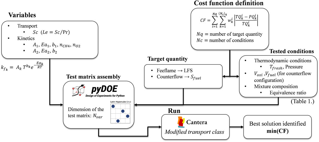
FIGURE 1. Schematic description of the reaction mechanism optimization procedure implemented in Python.
Once the variables have been defined, for a complete definition of the optimization problem, the cost function (CF) must be specified. In this work, CF is evaluated using Eq. 2, where TQ and PQ refer, respectively, to the target quantities and the predicted quantity on the laminar flame, while
The reference quantities chosen in this optimization process are LFS, computed from a 1D freely propagating flame, and the flame consumption speed
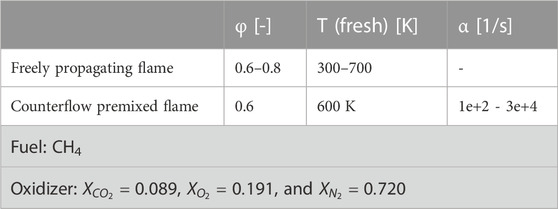
TABLE 1. Conditions considered for the evaluation of CF (Eq. 2).
The optimization problem is now completely defined; thus, in principle, the minimization of CF can be afforded in multiple ways. In this work, because of the simplicity of the reaction mechanism and the low computational cost of each single-flame evaluation, the design of the experiment procedure has been chosen to explore the variable space and find the CF minima. The Latin hypercube sampling (lhs) method has been adopted to assemble the variable test matrix that has the dimension
2.2 Chemical kinetics results
The set of variables for the new reaction mechanism, identified after the optimization process, is presented in Table 2.
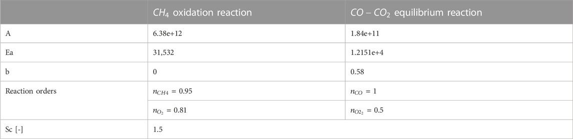
TABLE 2. Summary of the optimized mechanism kinetics and transport parameters. Units: cal, K, mol, cm3, and s.
The performances of the two-step BFER_CO2* reaction mechanism in terms of LFS prediction are shown in Figure 2. This is in accordance with the reference GRI3.0 mechanism in the whole range of conditions included in the optimization. Focusing on the prediction of BFER_CO2*, the accuracy gets better at 600 K and φ = 0.6, which are exactly the fresh mixture conditions for turbulent combustion investigations presented in the next paragraph. This was made possible by the proper choice of the
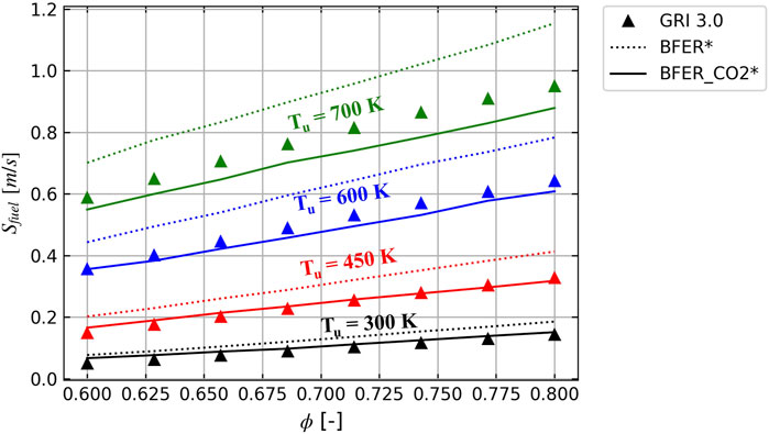
FIGURE 2. Comparison of the atmospheric unstretched LFS predicted by the original (BFER*) and the improved mechanisms (BFER_CO2*) against the reference detailed scheme (GRI30). The colors represent the different unburnt mixture temperatures: 700 K— green, 600 K— blue, 450 K— red, and 300 K— black.
The prediction of the BFER* mechanism always overestimates the reactivity, and this is expected mostly to be due to the kinetic effect of the CO2 dissociation reactions. The BFER* was optimized for conditions in which these dissociation reactions play a marginal role, but as pointed out by Xie et al. (2020), these reactions should gain importance by increasing CO2 enrichment, affecting the global fuel consumption capacity.
However, unlike BFER*, BFER_CO2* does not include any pre-exponential adjustment (PEA). The PEA allows the pre-exponential factor A to be dependent on the local
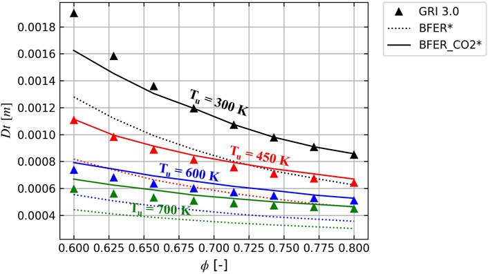
FIGURE 3. Comparison of the atmospheric unstretched laminar flame thickness predicted by the original (BFER*) and the improved mechanisms (BFER_CO2*) against the reference detailed scheme (GRI30). The colors represent the different unburnt mixture temperatures: 700 K— green, 600 K— blue, 450 K— red, and 300 K— black.
As highlighted in Table 1, the reaction mechanism has been optimized considering counterflow premixed flames in the fresh-to-burnt configuration at various strain rate levels. The prediction of the BFER_CO2* mechanism is not accurate in increasing the strain rate level, even though the Schmidt number has been included in the variables for optimization. In any case, the Schmidt number finally chosen allows the best reconstruction of the laminar consumption speed increasing the strain (Figure 4).
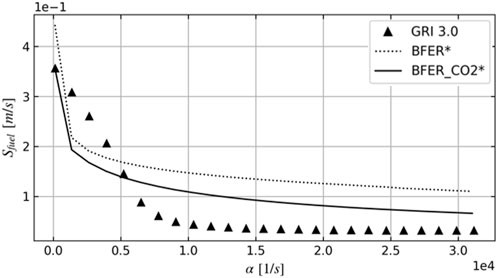
FIGURE 4. Sensitivity of LFS to the strain predicted by the original (BFER*) and improved mechanisms (BFER_CO2*) against the reference detailed scheme (GRI30). The simulations are relative to a fresh-to-burnt counterflow premixed flame at atmospheric pressure.
3 Turbulent combustion test case
An experimental test case has been chosen to assess the prediction of the kinetics scheme in the context of turbulent combustion. In the following section, the experimental facility and the selected test points are described. Afterward, the setup description and the results discussion of the high-fidelity numerical simulations are presented.
3.1 Experimental test rig
The experimental rig is described in De Persis et al. (2013). The facility architecture, shown in Figure 5, consists of an inlet plenum, an axial swirler, and a cylindrical Herasil quartz combustion chamber. The rig is operated at atmospheric pressure under fully premixed conditions. The CO2/air/CH4 mixture is prepared in the mixing volume upstream the swirler so that when it enters the combustion chambers, it can reasonably be assumed perfectly premixed. The fresh mixture can be heated up to 700 K to reproduce the gas turbine combustors’ inlet temperature levels. The objective of the experimental study was to investigate the effect of the CO2 dilution on the flame stability and the corresponding change in the flame topology. The researchers have analyzed a wide range of operating conditions by varying the equivalence ratio and the CO2 content in the fresh mixture. The observed flame shape changed from a lifted anchored condition toward the extinction, increasing the CO2 dilution. It is worth noting that the CO2 dilution adopted in this experimental study is not actually consistent with any EGR level. The relative N2 content in EGR is expected to be higher than that in a pure CO2 dilution.
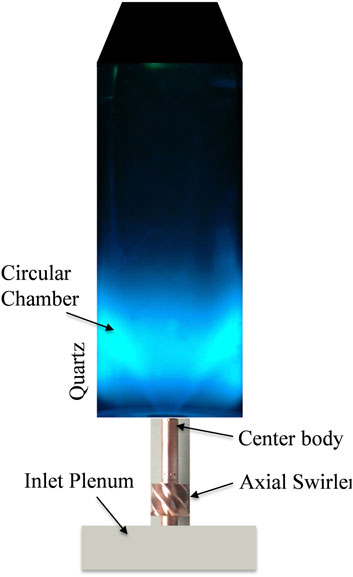
FIGURE 5. Schematic representation of the experimental facility (De Persis et al., 2013).
The experimental apparatus consists of an ICCD camera for detecting CH* chemiluminescence and a gas analyzer for investigating the composition of the exhaust gases.
The details of the two high-temperature test points selected for the numerical models’ validation are reported in Table 3.
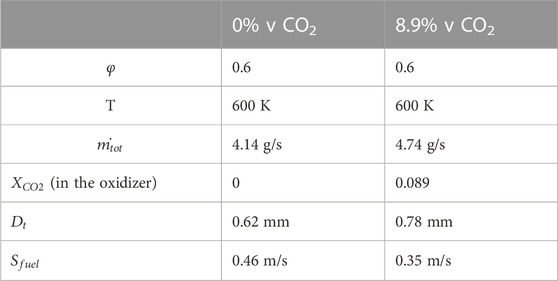
TABLE 3. Selected test point operating conditions and the corresponding unstretched laminar flame characteristics.
3.2 Numerical setup and computational domain
Reactive high-fidelity simulations have been carried out using the fully compressible AVBP code (CERFACS, 2023). The third order in time and space TTGC numerical scheme (Colin and Rudgyard, 2000) has been used to discretize the convective term of the Navier–Stokes equations. The time discretization is explicit, and the timestep is automatically chosen in order to ensure a constant maximum CFL = 0.7. The dynamic Smagorinsky–Lilly formulation (Lilly, 1992) is used to treat the sub-grid fluctuations.
The turbulence chemistry interaction has been modeled using ATFM (Colin et al., 2000) with a constant thickening factor selected to ensure a constant number of grid points in the unstretched laminar flame front equal to 5.
The computational domain is shown in Figure 6. At the inlet plenum, the mass flow condition is specified, whereas in the outlet plenum, the atmospheric pressure is prescribed on the dome and an auxiliary co-flow inlet has been assigned to the plenum ring. All the inlet and outlet boundaries are modeled with partially non-reflecting Navier–Stokes characteristic boundary conditions (NSCBCs) (Poinsot and Lelef, 1992). All the walls are modeled via the wall function approach. A fixed temperature has been imposed on the wall boundaries in the combustion chamber, and the estimated temperatures for the quartz, backplate, and the center body are 1000, 900, and 900 K, respectively. In terms of inlet temperature, mixture composition, and mass flow, the numerical boundary conditions are the same as described in Table 3 for the experimental test point.

FIGURE 6. Computational domain and mesh detail in the flame stabilization region.
3.3 Numerical results
The results discussion is organized as follows: first, the assessment of the flame prediction is focused with respect to the experimental measurements. Afterward, the impact of the heat loss on the flame shape is discussed, and finally a brief characterization of the numerically predicted flame dynamics is provided.
3.3.1 Flame prediction assessment
In Figure 7, the line of sight (LOS) of the time-averaged heat release rate (HR) is compared to the experimental CH* chemiluminescence for the two investigated cases. The numerical prediction of the flame for the case without CO2 addition shows an M-shaped flame, which is stabilized near the swirler exit. However, only a weak trace of HR can be identified near the center body of the swirler and the backplate, where the wall heat loss plays a key role in the inhibition of flame stabilization, which will be pointed out later. Upon increasing the CO2 content, the predicted flame topology changes, and the anchoring on the external shear layer gets completely lost. Moreover, in this CO2-enriched case, a certain axial shift of the HR peak can be observed, indicating that the flame is globally approaching the blow-off due to the increase in both the CO2 content and the mass flow. From this perspective, the simulations have been found capable of predicting the global change in the flame shape as well as the change in the stabilization mechanism observed experimentally, which is the main objective of this model validation experiment. Some discrepancies exist between the experimental and prediction results; there exist differences between the experimental CH* and the numerical heat-released map. An explanation for these discrepancies is that different quantities are considered for the comparison of the numerical and experimental data. The CH* is not necessarily fully representative of the heat release rate. In particular, for a very thick flame front and nearly distributed reaction zone (CO2 diluted case), the comparison would not be so straightforward. The thick flame front would amplify the differences in the production region of the CH* with respect to the heat released, resulting in a mismatch between the two fields. Lauer et al. (2011) developed a procedure to correct the CH* and OH* chemiluminescence fields to retrieve the heat-released field. From the experimental data that are considered in this study, there is no possibility to perform such correction on the CH* field due to the lack of information about the flow field. A second possible reason for the observed difference is that when CO2 is added, the flame approaches the blowout and its luminosity is expected to decrease significantly with the increasing noise. Eventually, the experimental investigation was not conducted aiming at validating numerical models, so there is a lack of data, such as the thermal boundary conditions and the flow field. On the other hand, this test case is the only study in the literature that characterizes an open geometry with optical measurements.
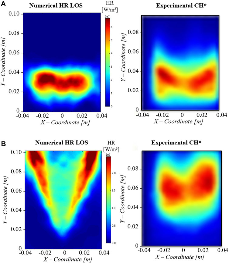
FIGURE 7. Comparison between the numerical time-averaged heat release rate (left) and the experimental CH* chemiluminescence (right) for the (A) CH4–air case and (B) CH4/CO2/air case. All the maps are line-of-sight integrated.
From the numerical side, the uncertainty of the wall thermal boundary partially precludes the accuracy of the solution in some regions. To highlight the role of the heat loss, the following section is dedicated to the investigation of the enthalpy defect effect on the local flame reactivity.
3.3.2 Impact of heat loss on the flame
To investigate the role of wall heat loss (HL) in affecting the combustion process, the enthalpy
Here,
Figure 8 shows the
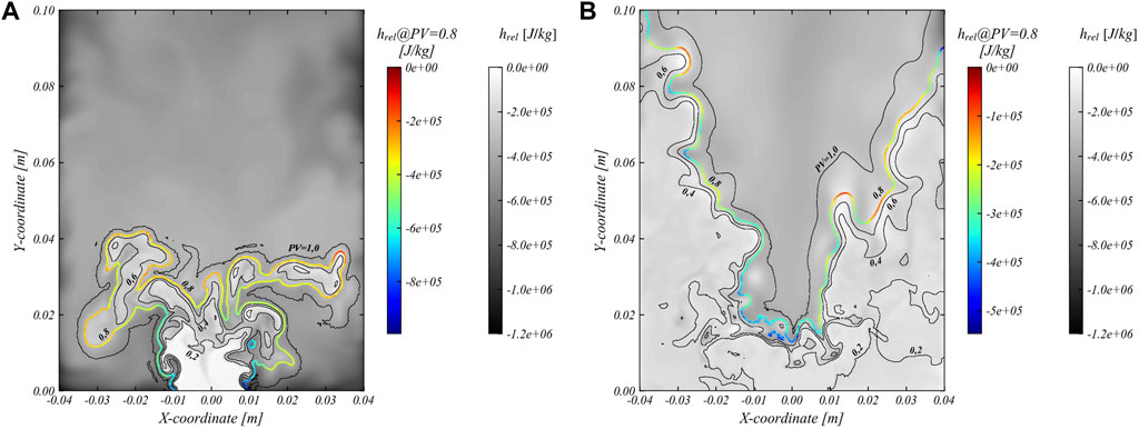
FIGURE 8. Instantaneous relative enthalpy contour. The isolines represent the progress variable computed according to Equation 7, with the PV = 0.8 isoline colored with the local relative enthalpy. (A) CH4–air case; (B) CH4/CO2/air case.
Here,
Defining the flame stretch as the sum of the strain and curvature contribution (Poinsot and Veynante, 2005), the role of the flame front curvature on the local HL can be identified on the PV = 0.8 isoline (Figure 8B); the negative flame curvature regions are characterized by higher
Investigating the stability characteristics of the flame is particularly interesting due to the effect of HL on the flame speed and, analogously, on the related HR. For this purpose, in Figure 9 the scatterplot of HR and PV has been reported with respect to the local
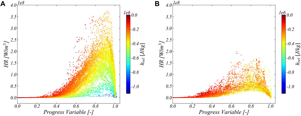
FIGURE 9. Instantaneous heat release rate dependence on the local progress variable on the chamber midplane colored by the level of relative enthalpy. (A) CH4–air case; (B) CH4/CO2/air case.
3.3.3 Flame dynamics
The increase in the CO2 content of the fresh gas mixture has been found to significantly cause changes in the flame dynamics in the simulations. In Figure 10, the pressure oscillations in the plenum and combustion chamber (CC) have been reported together with the mean instantaneous HR of the two cases. In the CH4–air case (Figure 10A), high-amplitude-pressure oscillations of the order of 5 kPa have been observed in CC, whereas the pressure oscillations appear strongly dumped in the inlet plenum, where the fluctuations are 100 Pa. Similar high-amplitude and low-frequency fluctuations are also observed in the mean HR signal for the CH4–air case. With the addition of CO2 in the mixture (Figure 10B), the pressure oscillations in the combustion chamber decrease in terms of amplitude and are comparable to the oscillations observed in the inlet plenum (200–500 Pa). In Figure 11, the similar signals in the frequency domain have been reported, and the aligned peaks in all the signals at the frequency of 356 Hz (Figure 11A) suggest the presence of a certain thermoacoustic coupling between the heat release rate and pressure fluctuations. On the contrary, for the CO2-enriched case (Figure 11B), the pressure fluctuations appear decoupled from HR, and the two high-frequency peaks observed (Figure 11B) are completely out of the frequency range that could trigger any thermoacoustic coupling.
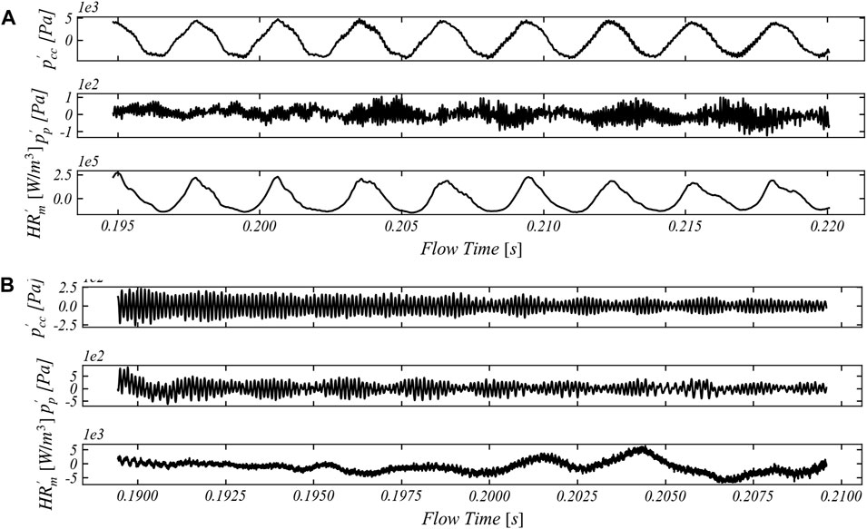
FIGURE 10. Predicted fluctuations of pressure in the combustion chamber
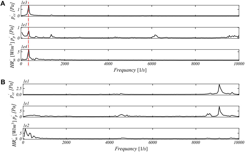
FIGURE 11. FFT of the signal of pressure in the combustion chamber
A visualization of the periodic flame dynamics for the CH4–air case is shown in Figure 12. In the first snapshot (Figure 12A), the combustion chamber’s instantaneous pressure is near its minimum, and the flame is very compact near the swirler exit, resulting in a global low heat release rate. The temporary lower pressure of the chamber with respect to the plenum enhances the fresh mixture entering the combustion chamber with a higher velocity. This is confirmed by the vector plot superimposed on the HR contour, which shows the high-velocity region near the CC inlet. The rapid fresh mixture refill enhances the increase in HR in the next phase, which in turn makes the pressure increase consistent, decreasing the pressure drop across the swirler feeding channel. The consequent slowdown of the inlet fresh mixture enhances the rapid fuel consumption (Figure 12C) until the flame once again becomes more compact (with lower HR), allowing the pressure to decrease again (Figure 12D).
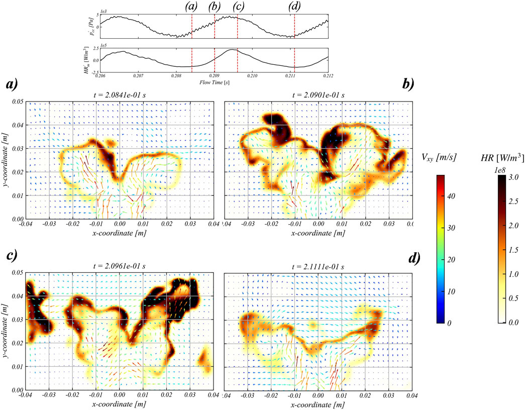
FIGURE 12. Instantaneous snapshots of the heat release rate and velocity vector on the midplane during a cycle of the flame dynamics for the CH4–air case. (A) Low CC pressure, high fresh mixture inlet velocity, low HR; (B) Pressure and HR increase with inlet velocity decrease; (C) Highest HR and pressure with lowest fresh mixture inlet velocity; (D) Lowest pressure and HR with Highest fresh mixture inlet velocity.
These differences in the thermoacoustic responses observed in the two investigated cases can be due to the change in the flame shape, which in turn affects the temperature field and, thus, the speed of sound. In general, as mentioned previously, the increase in the CO2 content of the mixture decreases the power density, and this has been found to be a beneficial effect in the mitigation of thermoacoustic coupling (ElKady et al., 2008; Evulet et al., 2009).
4 Conclusion
The impact of CO2 addition on a swirled stabilized CH4–air flame was numerically investigated. First, an automatic procedure for global reaction mechanism optimization has been presented and subsequently used to retrieve an optimized version of the BFER* two-step kinetics scheme for the CO2-enriched environment. The optimization has been carried out considering several parameters in order to improve the prediction of different flame configurations, thermodynamic conditions, and mixture compositions. The novel BFER_CO2* kinetics scheme shows that the level of accordance with the reference reaction mechanism is better for the freely propagating flames, whereas its response to the strain level of the premixed counterflow configuration could still be improved.
The BFER* and BFER_CO2* mechanisms have been used to perform high-fidelity CFD simulations trying to numerically reproduce two flames experimentally investigated by De Persis et al. (2013): first without CO2 dilution and second with 8.9% CO2 (by volume in the oxidized state). The numerical prediction has been found capable of qualitatively reproducing the change in the flame topology, which moves from a lifted M-shaped flame in the CH4–air case to a V-shaped flame with CO2 addition. The effect of HL has been found to be the discriminating factor which, through the reactivity slowing down near the backplate, induces the flame lift-off in the CH4–air case. With the CO2 addition and the change in the flame shape, the effect of HL on the reactivity is mitigated. The lower HR rates prove the essential role of CO2 in decreasing the speed capacity of the local flame consumption. This would have contributed to the change in flame shape and the stabilization mechanism observed in the two cases. Numerically, CO2 dilution leads to a strong mitigation of the pressure oscillations that are observed in the methane–air case. Overall, the model has shown a satisfactory level of agreement with the experimental data, paving the way for the setup application for the study of real EGR cases.
Data availability statement
The raw data supporting the conclusion of this article will be made available by the authors, without undue reservation.
Author contributions
SC: Python script writing, numerical simulation running, and post-processing results. PN and AA: revision and support. All authors contributed to the article and approved the submitted version.
Acknowledgments
The authors would like to thank Professor G. Cabot for sharing the experimental data and CERFACS for the grant to use the AVBP code and the customized Cantera build.
Conflict of interest
The authors declare that the research was conducted in the absence of any commercial or financial relationships that could be construed as a potential conflict of interest.
Publisher’s note
All claims expressed in this article are solely those of the authors and do not necessarily represent those of their affiliated organizations, or those of the publisher, the editors, and the reviewers. Any product that may be evaluated in this article, or claim that may be made by its manufacturer, is not guaranteed or endorsed by the publisher.
References
Adapted version of Cantera form CERFACS (2017). Adapted version of Cantera form CERFACS. Available at: https://www.cerfacs.fr/cantera/.
Burdet, A., Lachaux, T., De La Cruz García, M., and Winkler, D. (2010). “Combustion under flue gas recirculation conditions in a gas turbine lean premix burner,” in Proc. ASME Turbo Expo, Power for Land, 1083–1091. doi:10.1115/GT2010-23396
Burnes, D., Saxena, P., and Dunn, P. (2020). Study of using exhaust gas recirculation on a gas turbine for carbon capture. Proc. ASME Turbo Expo. doi:10.1115/GT2020-16080
Cailler, M., Darabiha, N., and Fiorina, B. (2020). Development of a virtual optimized chemistry method. Application to hydrocarbon/air combustion. Combust. Flame 211, 281–302. doi:10.1016/j.combustflame.2019.09.013
CERFACS (2023). THIS IS the website of the AVBP code of CERFACS AVBP. Available at: https://www.cerfacs.fr/avbp7x/.
Chan, Y. L., Zhu, M., Zhang, Z., Liu, P., and Zhang, D. (2015). The effect of CO2 dilution on the laminar burning velocity of premixed methane/air flames. Energy Procedia 75, 3048–3053. Elsevier B.V. doi:10.1016/j.egypro.2015.07.621
Chen, Y., Wang, J., and Zhang, X. (2020). Experimental and numerical study of the effect of CO2 replacing part of N2 present in air on CH4 premixed flame characteristics using a reduced mechanism. ACS Omega 5 (46), 30130–30138. doi:10.1021/acsomega.0c04537
Cohé, C., Chauveau, C., Gökalp, I., and Kurtuluş, D. F. (2009). CO2 addition and pressure effects on laminar and turbulent lean premixed CH4 air flames. Proc. Combust. Inst. 32, 1803–1810. II. doi:10.1016/j.proci.2008.06.181
Colin, O., Ducros, F., Veynante, D., and Poinsot, T. (2000). A thickened flame model for large eddy simulations of turbulent premixed combustion. Phys. Fluids 12 (7), 1843–1863. doi:10.1063/1.870436
Colin, O., and Rudgyard, M. (2000). Development of high-order taylor-galerkin schemes for LES. J. Comput. Phys. 162 (2), 338–371. doi:10.1006/jcph.2000.6538
De Persis, S., Cabot, G., Pillier, L., Gökalp, I., and Boukhalfa, A. M. (2013). Study of lean premixed methane combustion with CO2 dilution under gas turbine conditions. Energy Fuels 27 (2), 1093–1103. doi:10.1021/ef3016365
Duva, B. C., Chance, L. E., and Toulson, E. (2020). Dilution effect of different combustion residuals on laminar burning velocities and burned gas Markstein lengths of premixed methane/air mixtures at elevated temperature. Fuel 267 (1), 117153. Elsevier. doi:10.1016/j.fuel.2020.117153
ElKady, A. M., Evulet, A., Brand, A., Ursin, T. P., and Lynghjem, A. (2008). “Exhaust gas recirculation in dln f-class gas turbines for post-combustion C02 capture,” in Proc. ASME Turbo Expo, 847–854. doi:10.1115/GT2008-51152
Erete, J. I., Hughes, K. J., Ma, L., Fairweather, M., Pourkashanian, M., and Williams, A. (2017). Effect of CO2 dilution on the structure and emissions from turbulent, non-premixed methane–air jet flames. J. Energy Inst. 90 (2), 191–200. Elsevier Ltd. doi:10.1016/j.joei.2016.02.004
Evulet, A. T., Elkady, A. M., Branda, A. R., and Chinn, D. (2009). On the performance and operability of GE’s dry low NO combustors utilizing exhaust gas recirculation for PostCombustion carbon capture. Energy Procedia 1, 3809–3816. doi:10.1016/j.egypro.2009.02.182
Franzelli, B. G. (2011). Impact of the chemical description on direct numerical simulations and large eddy simulations of turbulent combustion in industrial aero-engines, 270. PhD.
Galmiche, B., Halter, F., Foucher, F., and Dagaut, P. (2011). Effects of diluents addition on laminar burning velocity of premixed methane/air flames. Energy and Fuels 39, 1557–1562. doi:10.3969/j.issn.0253-374x.2011.10.027
Guethe, F., Stankovic, D., Genin, F., Syed, K., and Winkler, D. (2011). “Flue gas recirculation of the Alstom sequential gas turbine combustor tested at high pressure,” in Proc. ASME Turbo Expo, 399–408. doi:10.1115/GT2011-45379
Halter, F., Foucher, F., Landry, L., and Mounaïm-Rousselle, C. (2009). Effect of dilution by nitrogen and/or carbon dioxide on methane and iso-octane air flames. Combust. Sci. Technol. 181 (6), 813–827. doi:10.1080/00102200902864662
Han, D., Satija, A., Gore, J. P., and Lucht, R. P. (2018). Experimental study of CO2 diluted, piloted, turbulent CH4/air premixed flames using high-repetition-rate OH PLIF. Combust. Flame 193, 145–156. Elsevier Inc. doi:10.1016/j.combustflame.2018.03.012
Han, D., Satija, A., Kim, J., Weng, Y., Gore, J. P., and Lucht, R. P. (2017). Dual-pump vibrational CARS measurements of temperature and species concentrations in turbulent premixed flames with CO2 addition. Combust. Flame 181, 239–250. Elsevier Inc. doi:10.1016/j.combustflame.2017.03.027
Hejie, L., Ahmed, E., and Andrei, E. (2009). “Effect of exhaust gas recirculation on NOx formation in premixed combustion system,” in 47th AIAA Aerospace Sciences Meeting including The New Horizons Forum and Aerospace Exposition, Orlando, Florida, 05 January 2009 - 08 January 2009, 1–12. doi:10.2514/6.2009-226
Jourdaine, P., Mirat, C., Caudal, J., Lo, A., and Schuller, T. (2017). A comparison between the stabilization of premixed swirling CO2-diluted methane oxy-flames and methane/air flames. Fuel 201, 156–164. Elsevier Ltd. doi:10.1016/j.fuel.2016.11.017
Kobayashi, H., Hagiwara, H., Kaneko, H., and Ogami, Y. (2007). Effects of CO2 dilution on turbulent premixed flames at high pressure and high temperature. Proc. Combust. Inst. 31 (1), 1451–1458. I. doi:10.1016/j.proci.2006.07.159
Lauer, M., Zellhuber, M., Sattelmayer, T., and Aul, C. J. (2011). Determination of the heat release distribution in turbulent flames by a model based correction of OH* chemiluminescence. J. Eng. Gas Turbines Power 133 (12), 1–9. doi:10.1115/1.4004124
Li, H., Ditaranto, M., and Berstad, D. (2011). Technologies for increasing CO2 concentration in exhaust gas from natural gas-fired power production with post-combustion, amine-based CO2 capture. Energy 36 (2), 1124–1133. Elsevier Ltd. doi:10.1016/j.energy.2010.11.037
Lilly, D. K. (1992). A proposed modification of the Germano subgrid-scale closure method. Phys. Fluids 4 (3), 633–635. doi:10.1063/1.858280
Nassini, P. C., Pampaloni, D., Meloni, R., and Andreini, A. (2021). Lean blow-out prediction in an industrial gas turbine combustor through a LES-based CFD analysis. Combust. Flame 229, 111391. Elsevier Inc. doi:10.1016/j.combustflame.2021.02.037
Poinsot, T. J., and Lelef, S. K. (1992). Boundary conditions for direct simulations of compressible viscous flows. J. Comput. Phys. 101 (1), 104–129. doi:10.1016/0021-9991(92)90046-2
Poinsot, T., and Veynante, D. (2005). Theoretical and numerical combustion. 2. Morningside, Australia: R.T. Edwards Commercial.
Smith, G. P., Golden, D. M., Frenklach, M., Moriarty, N. W., Eiteneer, B., Goldenberg, M., et al. (2000). gri3.0. Available at: http://combustion.berkeley.edu/gri-mech/.
Vandel, A., Chica Cano, J., de Persis, S., and Cabot, G. (2020). Study of the influence of water vapour and carbon dioxide dilution on flame structure of swirled methane/oxygen-enriched air flames. Exp. Therm. Fluid Sci. 113, 110010. Elsevier. doi:10.1016/j.expthermflusci.2019.110010
Xie, M., Fu, J., Zhang, Y., Shu, J., Ma, Y., Liu, J., et al. (2020). Numerical analysis on the effects of CO2 dilution on the laminar burning velocity of premixed methane/air flame with elevated initial temperature and pressure. Fuel 264, 116858. Elsevier. doi:10.1016/j.fuel.2019.116858
Nomenclature
Keywords: exhaust gas recirculation, artificially thickened flame model, high-fidelity simulation, reaction mechanism calibration, large eddy simulation
Citation: Castellani S, Nassini PC and Andreini A (2023) Optimization of a two-step CH4/air reaction mechanism in a CO2-enriched environment for high-fidelity combustion simulations. Front. Mech. Eng 9:1240761. doi: 10.3389/fmech.2023.1240761
Received: 15 June 2023; Accepted: 25 September 2023;
Published: 13 October 2023.
Edited by:
Tanvir I. Farouk, University of South Carolina, United StatesCopyright © 2023 Castellani, Nassini and Andreini. This is an open-access article distributed under the terms of the Creative Commons Attribution License (CC BY). The use, distribution or reproduction in other forums is permitted, provided the original author(s) and the copyright owner(s) are credited and that the original publication in this journal is cited, in accordance with accepted academic practice. No use, distribution or reproduction is permitted which does not comply with these terms.
*Correspondence: S. Castellani, c2ltb25lLmNhc3RlbGxhbmlAdW5pZmkuaXQ=