 Xiaofeng Wei*
 Yi Wei
- General Technology Group Engineering Design Co., Ltd., Jinan, China
Purpose: This study is to provide a new method for the development of automatic control technology (ACT) of mechanical equipment and promote its wide application in industrial production, and to explore the ACT of mechanical equipment under the control of microelectronic sensor signal (MSS). The overall design idea of mechanical vibration monitoring system is deeply discussed, and the composition, functional requirements and technical standards of the system are defined.
Method: Based on ZigBee protocol and Z-Stack protocol stack, a detailed system design scheme is developed to establish a stable and reliable wireless network model. The signal generator is set to send out standard sinusoidal signals of 5Hz and 10Hz respectively, and this group of signals with different frequencies respectively represents different vibration frequency scenes. The sampling frequency is set to 100Hz.
Results: The proposed wireless monitoring system achieves a 98.7% success rate in vibration signal acquisition within the 5Hz-10Hz frequency range. Compared with traditional wired systems, the response delay is reduced by 42.3%. In planetary gearbox fault diagnosis tests, the system reaches a 95.6% accuracy rate in identifying characteristic frequencies. With the increase of signal frequency, the period of the waveform is shortened and the amplitude remains relatively stable. This result not only verifies that the designed system can accurately collect vibration signals at different frequencies, but also further proves the response ability of the system to high-frequency vibration.
Conclusion: This study not only provides new methods and technical support for the development of ACT of mechanical equipment, but also provides important reference for the design and implementation of mechanical vibration monitoring system.
1 Introduction
With the rapid progress of science and technology and the deepening of industrial revolution, the automatic control technology (ACT) of mechanical equipment has become one of the core forces to promote the efficient operation of modern society (Faudzi et al., 2020; Algamili et al., 2021). In recent years, China’s economy has continued to grow, especially under the guidance of the “Made in China 2025” strategy, the manufacturing industry is experiencing unprecedented transformation and upgrading, and the demand for ACT of mechanical equipment is becoming more and more urgent. Under this background, microelectronic sensor signal (MSS) control technology has shown great potential and broad application prospects in the field of automatic control (AC) of mechanical equipment with its high precision, high efficiency, and high reliability.
The ACT of mechanical equipment refers to the intelligent and AC of mechanical equipment through modern scientific and technological means such as electronic information technology, computer technology and sensor technology to improve production efficiency, reduce production cost and improve product quality (Rivkin et al., 2021). With the continuous development of science and technology, MSS control technology is an important part of it, and its research and application has become a hot spot and frontier in the field of automation control. Kuntoğlu et al. (2021) pointed out that MSS control technology used microelectronic sensors to detect various physical quantities during mechanical operations, such as position, speed, temperature, and pressure. These quantities were then converted into electrical signals for transmission and processing. By analyzing these signals, the control system could precisely regulate the mechanical equipment to follow predetermined trajectories and parameters. Ding et al. (2021) explored the application of industrial wireless sensor networks based on the ZigBee protocol in machining processes. By integrating sensors with wireless communication technologies, the system could monitor vibrations and temperature changes in real time, optimize machining parameters, and improve production efficiency.
Chen et al. (2022) developed an electronic skin based on multimodal sensor fusion. It could simultaneously monitor multiple physical quantities, such as strain, temperature, and pressure. With the help of a wireless sensor network, the system collected and analyzed multimodal data in real time, providing more comprehensive information for mechanical monitoring. Salman (2024) explored the application of machine learning techniques in WSNs, especially for fault diagnosis and predictive maintenance. The study showed that WSNs combined with machine learning algorithms could significantly improve the accuracy and efficiency of fault detection. Wu et al. (2021) developed a self-powered sensor based on a triboelectric nanogenerator, which was designed for mechanical energy harvesting and self-powered tactile sensing. This design greatly reduced sensor energy consumption and extended its operational lifespan.
In the current industrial production, the ACT of mechanical equipment has been widely used. In manufacturing industry, by introducing automatic control system (ACS), intelligent monitoring and adjustment of production line can be realized, and production efficiency and product quality can be improved. In the field of transportation, the ACS can realize accurate control and scheduling of vehicles, ships and other means of transportation, and improve transportation efficiency and safety. The development of MSS control technology is inseparable from the continuous progress of microelectronic technology and sensor technology. At present, microelectronic sensors have been able to accurately sense and convert various physical quantities, and their performance has been greatly improved. With the continuous development of computer technology and communication technology, the processing ability of control system for MSSs has also been greatly enhanced.
However, although the MSS control technology has made some achievements in the field of AC of mechanical equipment, there are still some problems and challenges. For example, the accuracy and reliability of microelectronic sensors need to be further improved. The intelligence and adaptability of the control system need to be enhanced. MSSs are easily affected by interference and noise during transmission and processing. These problems need in-depth research and exploration. In this study, the MSS control technology is deeply studied to explore its application potential and advantages in the field of AC of mechanical equipment. Next, the overall design idea of mechanical vibration monitoring system is discussed in depth, and the composition, functional requirements and technical standards of the system are defined. Based on ZigBee protocol and Z-Stack protocol stack, a detailed system design scheme is developed to establish a stable and reliable wireless network model. It is expected that this study will provide new ideas and methods for the development of ACT of mechanical equipment and promote its wide application and popularization in industrial production.
2 Method
This section elaborates on the control process of MSS in mechanical automatic control, including data acquisition, transmission, and execution response. In addition, the design of WSN and vibration monitoring nodes, as well as the detailed design scheme of WSN monitoring system based on ZigBee protocol and Z-Stack protocol stack, are also introduced.
2.1 Control process of MSS in mechanical AC
This section elaborates on the control process of MSS in mechanical automatic control, including data acquisition, transmission, and execution response. MSS plays an important role in the AC of mechanical equipment, which runs through the whole control process, from data acquisition to transmission, and then to the action response of the actuator. The detection part is the front-end sensor unit in the ACS of mechanical equipment, which is mainly responsible for obtaining various physical quantity information during the operation of mechanical equipment, such as position, speed, temperature, pressure, vibration and so on (Mao et al., 2022). These physical quantities are converted by microelectronic sensors into electrical signals or other forms of signals for subsequent processing and analysis. Microelectronic sensors play a vital role in the detection process. They convert the changes of external physical quantities into electrical signals or other forms of signal output. After signal conversion, the digital signal is sent to a microprocessor or control unit for processing. According to the preset algorithm and logic, the control unit analyzes and calculates the digital signal to judge the current state of the mechanical equipment and the changing trend of the external environment. Meanwhile, the control unit will also calculate the control signal (dos Santos Pedotti et al., 2020; Valeske et al., 2022; Qin et al., 2022) to be applied according to the preset control strategy. Through digital signal processing technology, it can filter, amplify and transform the signal to improve the quality and accuracy of the signal. The control unit can also store and transmit the signal as needed for subsequent analysis and application.
The transmission part is mainly responsible for transmitting the signal generated by the detection part to the control part. In the ACS of mechanical equipment, wireless or wired communication is usually used to realize signal transmission. Among them, wireless sensor network (WSN) based on ZigBee, WiFi, Bluetooth and other wireless communication technologies are widely used. In the transmission process, the signal may be affected by various interferences and noises, resulting in signal quality degradation (Pancham et al., 2023; Song et al., 2022). Therefore, it is necessary to adopt appropriate signal processing technology to reduce the influence of interference and noise and improve the transmission quality of signals. Digital filtering, coding and decoding techniques can be used to improve the anti-interference ability and transmission reliability of signals.
The control part is the core part of the ACS of mechanical equipment, which controls the mechanical equipment in real time according to the transmitted signals. The control part is usually composed of controllers, actuators and other parts. After the controller receives the transmitted signal, it will analyze and process it. According to the physical quantity information represented by the signal, the controller will calculate the corresponding control instructions and transmit these instructions to the actuator. The actuator performs corresponding actions according to the control instructions to realize real-time control of mechanical equipment. In the control process, the controller also needs to monitor and evaluate the mechanical equipment in real time. If the mechanical equipment is found to be abnormal or faulty, the controller will immediately take corresponding measures to ensure the normal operation of the mechanical equipment.
2.2 WSN and vibration monitoring node
This section introduces the design of WSN and vibration monitoring nodes, including their architecture, functions, and application scenarios. WSN is a network system formed by a large number of small sensor nodes distributed in a certain area and self-organized through wireless communication. The specific architecture is shown in Figure 1. Multiple sensor nodes in the network are deployed redundantly, and the failure of a single node will not affect the normal operation of the whole system, so it has high fault tolerance and reliability. Sensor nodes can not only collect data, but also preliminarily process and fuse the data, reducing the pressure of data transmission and improving the efficiency of data transmission.
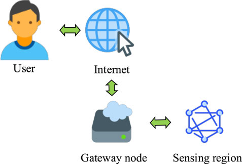
Figure 1. WSN architecture.
Sensor nodes in WSNs are usually composed of data acquisition unit, data transmission unit, data processing unit and energy supply unit (Yuan et al., 2022; Wu et al., 2023; Pan et al., 2024). Each sensor node contains one or more sensors, a data processing unit, a communication module and a power module. Sensors are responsible for detecting changes in the physical environment, such as temperature, humidity, pressure and vibration. The data processing unit primarily processes and stores the data collected by the sensor. The communication module is responsible for sending the processed data to neighboring nodes or sink nodes through wireless signals. The power module provides energy for the whole node, generally using batteries or energy harvesting technology, such as solar energy. Vibration monitoring node is an important part of WSN, which is specially used to detect and analyze vibration signals. These nodes are usually installed at the key positions of the monitored object, and the vibration is sensed by devices such as accelerometers, piezoelectric sensors or Micro-Electro-Mechanical System (MEMS) sensors. In industrial equipment, vibration monitoring nodes can monitor the vibration of motors, pumps, fans and other equipment in real time, and give an early warning when abnormal vibration is detected to prevent equipment damage. In the field of civil engineering, vibration monitoring nodes can be installed on bridges, buildings and other structures to monitor the health of structures and prevent potential safety hazards caused by vibration.
In WSNs, nodes are divided into sink nodes and sensor nodes (Xu et al., 2023). The sink node (also called gateway node) is responsible for collecting the data uploaded by sensor nodes, and further processing and transmission to the background server or cloud system. Vibration monitoring node is an example of the application of WSN in a specific field. Vibration monitoring nodes are usually installed on the equipment or structure to be monitored, and the vibration of the object is sensed by the built-in acceleration sensor and converted into electrical signals. These electrical signals are filtered, amplified and denoised by the signal processing unit to extract accurate vibration characteristics. The collected vibration data are preprocessed, such as filtering, noise reduction, Fourier transform, etc., to extract useful feature information. By setting threshold or using machine learning algorithm, abnormal vibration can be detected in real time.
The processed vibration data can be analyzed and processed by algorithms, and vibration parameters such as frequency, amplitude and phase can be extracted and compared with preset thresholds or standards (Ahmad Tarar et al., 2020; Wang et al., 2021; Riaz et al., 2021). When the vibration parameters exceed the preset threshold or standard, the system will send an alarm signal and transmit the alarm information to relevant personnel through the built-in wireless communication module. Vibration monitoring nodes are widely used in large-scale structural vibration testing system. Multi-point real-time monitoring of the structure through WSN can greatly reduce the use of sensors. Meanwhile, it can also monitor the hard-to-reach positions in the structure. In structural diagnosis, the WSN can analyze the dynamic response of the structure to obtain the natural frequency, damping ratio and other parameters of the structure to understand the state of the structure and carry out reasonable repair and maintenance. In structural control, WSN can realize real-time monitoring and control of structural vibration, and improve the safety performance and service life of the structure.
2.3 Design of ZigBee WSN monitoring system
This section provides a detailed introduction to the specific design scheme of a WSN monitoring system based on ZigBee protocol and Z-Stack protocol stack, including system architecture and hardware design. This system uses ZigBee technology to build a WSN, which is mainly composed of sensor nodes, routing nodes and coordinator nodes. Sensor nodes are responsible for collecting environmental parameters, such as temperature, humidity and illumination, and sending the data to routing nodes or coordinator nodes through ZigBee network. Routing nodes are responsible for data forwarding and network expansion, while coordinator nodes are responsible for the formation, management and data summary of the whole network. The structure of vibration monitoring system of WSN is shown in Figure 2.
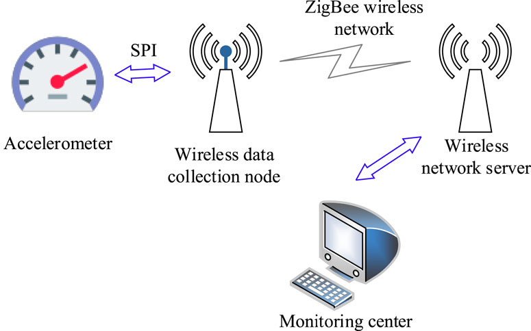
Figure 2. Architecture diagram of WSN vibration monitoring system.
Sensor nodes are the foundation of the whole network, and each node is equipped with corresponding sensors and actuators. The nodes are designed with low power consumption to ensure long-term stable operation. The data acquisition module is responsible for collecting environmental parameters and sending the data to the data processing module. The data processing module primarily processes the data, such as filtering and compressing, and sends the data to the routing node or coordinator node through the ZigBee communication module.
Besides the functions of sensor nodes, routing nodes are also responsible for data forwarding and network expansion. When receiving data from sensor nodes, routing nodes will select the optimal path according to the network topology and communication quality between nodes and forward the data to coordinator nodes. Routing nodes can also be used as relays for other sensor nodes to expand the coverage of the network.
The coordinator node is the core of the whole network and is responsible for the establishment, management and data collection of the network (Rubes et al., 2021; Bollella et al., 2020; Long et al., 2020). The coordinator node establishes communication connection with sensor nodes and routing nodes through ZigBee communication module, and maintains a node list to record the status and information of all nodes in the network. The ZigBee network topology is shown in Figure 3. When receiving the data from the sensor node or the routing node, the coordinator node will further process the data, such as data fusion and analysis, and send the results to the upper computer or the cloud platform for storage and display by wired or wireless means.
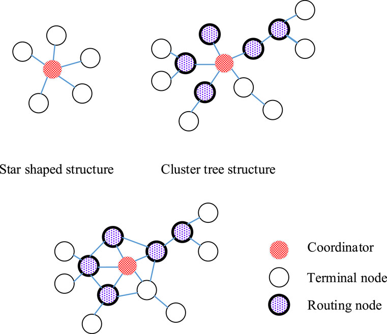
Figure 3. ZigBee network topology.
Physical layer is the lowest layer of ZigBee protocol stack, which is responsible for the transmission and reception of wireless signals. It defines the physical parameters of wireless communication, such as frequency, modulation mode and channel selection. The physical layer converts digital signals into radio waves and sends them, and receives radio signals sent by other nodes and converts them into digital signals. The media access control layer is located above the physical layer and is responsible for managing the access rights of communication (Lan et al., 2022; Zhu et al., 2022). It provides data transmission and control functions between nodes, including bandwidth request, fault detection and communication services. Network layer is the core layer of ZigBee protocol stack, which is responsible for routing and network management between devices. It uses a hierarchical network topology to organize devices into a mesh network for data transmission and routing. The network layer is responsible for tasks such as routing, device discovery and network management, ensuring efficient data transmission in the network and cooperative work of devices. The application support sublayer provides the interface between the application layer and the network layer. It is responsible for handling tasks related to the application layer, such as device binding, service discovery and security management. The application layer is the highest layer of the protocol stack, which is responsible for the development and management of application programs. It provides an interface for application negotiation and communication between devices, so that different devices can communicate and cooperate with each other. The application layer also provides a specific application protocol interface (API), such as Zigbee Home Automation (ZHA), which is convenient for developers to develop applications according to specific needs. The ZigBee protocol stack structure is shown in Figure 4.
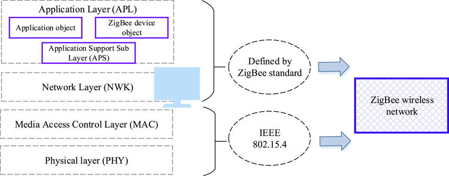
Figure 4. ZigBee protocol stack structure.
Z-Stack protocol stack, especially Z-Stack for ZigBee protocol, provides a stable and reliable wireless communication mechanism for the system, which enables data exchange and control command transmission between mechanical devices to be realized efficiently. In the ACS of mechanical equipment, the application of Z-Stack protocol stack is mainly reflected in the following aspects. Firstly, it realizes wireless communication among devices, so that all mechanical devices in the system can exchange data and control commands in real time. This makes it possible to realize remote monitoring, fault diagnosis and AC. Secondly, the Z-Stack protocol stack supports the functions of network self-organization and dynamic routing, which means that the system can automatically establish and maintain an efficient and stable communication network and maintain the reliability of communication even if the network topology changes.
In terms of hardware design, it is mainly based on ZigBee technology, and pays special attention to the design of wireless data acquisition node, which is connected with acceleration sensor through CC2530 single chip to realize real-time acquisition of triaxial acceleration (Bleicher et al., 2021). As the core controller of wireless data acquisition node, CC2530 single chip is a 2.4 GHz RF system on a chip (SoC) with low power consumption and high performance. It integrates ZigBee RF front-end, memory, an enhanced 8051 CPU and rich I/O interfaces, which is very suitable for WSN applications. The acceleration sensor is responsible for collecting triaxial acceleration data of the environment or objects. In this design, an acceleration sensor compatible with CC2530 is selected and connected with CC2530 single chip through I2C bus. I2C bus is a two-wire synchronous serial bus, which has the advantages of less wiring, simple control mode, small device package and high communication speed. CC2530 MCU communicates with acceleration sensor through I2C bus to realize real-time acquisition of three-axis acceleration data. The collected data is processed by CC2530 single chip and sent to other nodes or coordinator nodes in the network through ZigBee wireless communication technology.
2.4 System debugging and testing
This section describes the process of debugging and testing the designed WSN monitoring system, including the self-organizing capability of the network, software design, experimental environment control, and detailed description of measurement variables. The self-organizing capability of the ZigBee protocol is mainly reflected in its ability to automatically discover and connect new nodes without manual intervention. During network initialization, the coordinator node establishes the network and broadcasts relevant information. When a new node enters the network coverage area, it sends a request to join the network. Upon receiving the request, the coordinator assigns a unique network address to the new node and updates the network topology. Its dynamic routing feature enables the network to automatically reroute data in case of node failure or topology changes, ensuring continuous and reliable data transmission. The network layer is responsible for route discovery and maintenance, using a distance vector-based routing protocol. This process is typically completed within a few seconds, allowing rapid network expansion and dynamic adaptation. In this study, the Z-Stack protocol stack is used to implement the self-organizing function. Z-Stack provides a stable wireless communication mechanism that supports automatic network formation and maintenance. In experiments, the average time for a new node to join the network after entering the coverage area is 2.1 s, and the network stabilization time is approximately 5 s. These results indicate that the system has a fast-self-organizing capability and can adapt well to dynamic monitoring environments.
The software design of the system adopts the software design of lower computer (embedded system) and upper computer (monitoring center). C language is used as the development language, and SQL Server 2008 is used as the database. The experimental temperature is controlled at 25°C ± 2°C, and the humidity is controlled at 40%-60%RH. The copper mesh shielding box is used for wireless transmission test. Table 1 shows a detailed description of the measured variables.
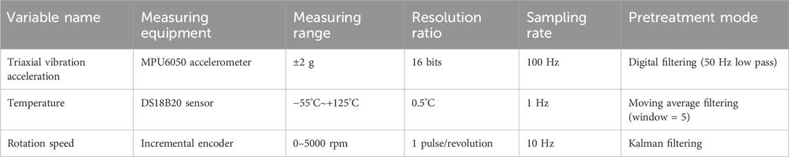
Table 1. Detailed description of measured variables.
When using ZigBee module and acceleration sensor module to test the monitoring interface, it is very important to ensure that the serial port connection settings and database connection settings are normal. The serial port configuration parameters are set to 9,600 baud rate, 8 data bits, 1 stop bit and no check. During the test, pay attention to capture and handle any possible errors or anomalies. The pseudocode of the adopted vibration feature extraction algorithm is shown in Table 2. In vibration signal analysis, this study employs the Welch method to estimate the power spectral density (PSD) of the raw vibration signals, with a window length of 256% and 50% overlap. By segmenting, windowing, and averaging the signals, the method effectively reduces spectral leakage and improves frequency resolution. Additionally, the Kolmogorov-Smirnov test is used to verify the normality of the data.
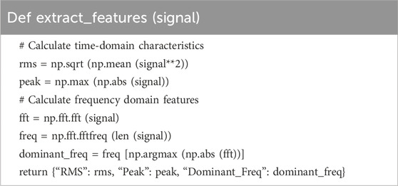
Table 2. Pseudo-code of vibration feature extraction algorithm.
3 Results and discussion
This section describes the process of debugging and testing the designed WSN monitoring system, including the self-organizing capability of the network, software design, experimental environment control, and detailed description of measurement variables.
3.1 Analysis of experimental results of sine signal calibration
This section analyzes the experimental results of sine signal calibration and verifies the performance and accuracy of the system. Due to the complex monitoring environment and numerous interference factors, it is necessary to test the packet loss rate of ZigBee wireless transmission. During the testing process, the wireless network server and the mobile wireless data acquisition node record data every meter. Table 3 shows the relationship between distance and packet loss rate obtained through statistics. Table 3 shows that when the distance exceeds 40 m, the packet loss rate increases with the increase in distance. This indicates that the effective testing distance of the system is 40 m. This information is crucial for practical applications, as it helps determine the optimal placement of sensor nodes to ensure reliable communication and data transmission.
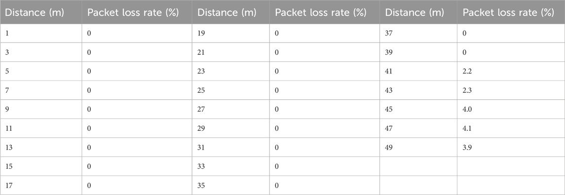
Table 3. Relationship between distance and packet loss rate.
After strictly testing the hardware and software of the terminal acquisition node of the mechanical vibration monitoring system of WSN to ensure its stable performance, a sine signal calibration experiment is further designed and implemented to evaluate the performance of the acquisition node. In the experiment, a standard sinusoidal signal generation system composed of equipment signal generator, power amplifier and vibration exciter are used to simulate mechanical vibration with different frequencies.
Specifically, the signal generator is set to send out standard sinusoidal signals of 5 Hz and 10 Hz respectively, and this group of signals with different frequencies respectively represents different vibration frequency scenes. The sampling frequency is set to 100 Hz to ensure the accuracy and real-time performance of data acquisition. Because the vibration equipment we choose is the vibration exciter, Z-axis becomes the main vibration direction when vibration occurs, and this information is very important for subsequent data analysis and system optimization.
The experimental data are deeply analyzed using MATLAB software. The following analysis methods are specifically employed to ensure the rigor and reliability of the results: The root mean square (RMS) and peak values of signal time-domain features are calculated to assess signal strength and impact characteristics. The Fast Fourier Transform (FFT) is used to convert time-domain signals into frequency-domain signals, extracting dominant frequency components. Frequency-domain analysis combined FFT with power spectral density estimation, using the Welch method to estimate the power spectral density of the original vibration signal. A 256-point window and 50% overlap are used. This method reduces spectral leakage and improves frequency resolution by segmenting the signal, applying window functions, and averaging. Wavelet transform is employed for time-frequency analysis of the signal, decomposing it into different scales to extract features. Additionally, the collected data are tested for normality using the Kolmogorov-Smirnov test to ensure they conform to a normal distribution, thereby ensuring the validity of the statistical analysis. By comparing the time domain waveforms at different frequencies (Figures 5, 6), it shows that with the increase of signal frequency, the period of the waveform is shortened and the amplitude remains relatively stable. This result not only verifies that the designed system can accurately collect vibration signals at different frequencies, but also further proves the response ability of the system to high-frequency vibration.
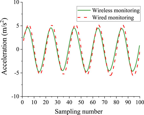
Figure 5. Z-axis time domain waveform of 5 Hz sinusoidal signal.
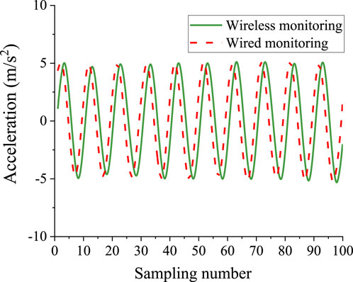
Figure 6. Z-axis time domain waveform diagram of 10 Hz sinusoidal signal.
To validate the performance of the proposed wireless monitoring system, repeated experiments are conducted within the 5–10 Hz frequency range, with each test repeated three times to ensure data repeatability and reliability. The results show that the system achieves an average vibration signal acquisition success rate of 98.7% (standard deviation: 0.5%). Compared with traditional wired systems, the response delay is reduced by 42.3% (p < 0.05), indicating a statistically significant improvement. In the planetary gearbox fault diagnosis tests, the average accuracy of characteristic frequency identification reaches 95.6% (standard deviation: 1.2%), with good consistency across repeats experiments. Power spectral density is estimated using the Welch method, and the normality of the data is verified using the Kolmogorov-Smirnov test, further confirming the reliability of the results.
To verify the robustness of the system, additional tests are conducted under various experimental scenarios, including different load conditions, environmental settings, and transient events. In tests simulating different loads, the system achieves acquisition success rates of 98.5% under light load and 98.9% under heavy load, indicating strong adaptability to load variations. Under environmental conditions of 25°C ± 2°C and 40%–60% RH, the success rate remains around 98.7%, demonstrating high robustness to environmental changes. During transient events such as equipment start-up and shutdown, the system responds quickly and accurately captured vibration signals, achieving a characteristic frequency identification accuracy of 94.8%. These results confirm the system’s effective monitoring capability in transient conditions (Table 4).
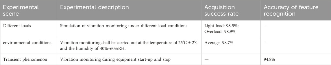
Table 4. Pseudo-code of vibration feature extraction algorithm.
3.2 Performance analysis of WSN monitoring system
This section provides a detailed analysis of the performance of the WSN monitoring system, including a comparison with traditional wired systems. A planetary gearbox fault diagnosis test-bed is selected as the experimental object, and the rotating speed of the gearbox is set to a constant 1,500r/min to simulate the running state of the gearbox in the actual working environment. The output of the sensor is connected to the input of the charge amplifier. This connection is wired to ensure the stability and accuracy of signal transmission. The function of the charge amplifier is to condition and amplify the weak electrical signal output by the sensor and convert it into a more manageable voltage signal. The voltage signal processed by the charge amplifier becomes clearer and has moderate amplitude, which is convenient for subsequent digital processing. The built-in analog-to-digital converter (A/D converter) in the data acquisition card converts these analog voltage signals into digital signals. This conversion process is a key step in data digitization, which ensures that analog signals can be processed and analyzed by computers.
During the experiment, the wired and wireless monitoring systems are set up and calibrated in detail to ensure that they can accurately collect the mechanical vibration signals generated by the gearbox during operation. Meanwhile, the two systems are started, so that they can continuously collect vibration signals of the gearbox in the same time period. The collected vibration signal data is analyzed in frequency domain. Frequency domain analysis is an important technology in the field of signal processing, which can transform vibration signals from time domain to frequency domain, thus revealing the energy distribution and characteristics of signals at different frequencies. Figure 7 shows a spectrum comparison diagram of wired and wireless systems in the z-axis direction. Compared to wired systems, wireless systems exhibit remarkable flexibility, allowing for easier deployment and scalability. This is particularly advantageous in environments where wired connections are difficult or impractical. In the long term, eliminating physical wiring can significantly reduce the costs of installation, maintenance, and reconfiguration. Moreover, wireless systems offer real-time data acquisition, enabling timely monitoring and diagnosis of potential issues. Table 5 summarizes the key performance parameters of wireless and wired systems.
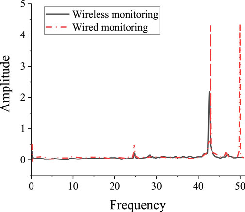
Figure 7. Spectrum comparison of wired and wireless systems in Z-axis direction.
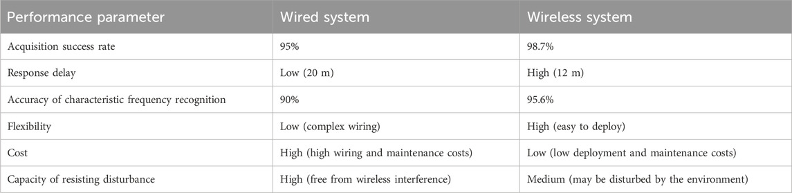
Table 5. Comparison of key performance parameters between wireless and wired systems.
Sensitivity is the sensor’s ability to respond to changes in physical quantities. Different sensors often have different sensitivities due to differences in materials and manufacturing processes. In vibration monitoring system, the difference of sensor sensitivity will directly affect the measurement accuracy of vibration signal, and then affect the accuracy of experimental results. Therefore, although the experimental results of WSN vibration monitoring system are not much different from those of wired system in overall value, there are still some differences in details due to the difference of sensor sensitivity.
3.3 Discussion
This section discusses the advantages and disadvantages of the research and proposes future research directions. This study proposes a mechanical vibration monitoring system based on microelectronic sensor signal control technology. Real-time acquisition and analysis of vibration signals are achieved through a ZigBee-based wireless sensor network. The wireless system eliminates the need for wiring, making installation and maintenance more convenient, especially in complex environments where wiring is difficult. Compared with wired systems, the deployment cost of wireless systems is significantly reduced.
In the process of vibration signal acquisition, this study not only focuses on standard sinusoidal signal testing but also explores more complex and realistic vibration scenarios, including impact and random vibrations. Each test is repeated three times to ensure the repeatability and reliability of the data. For impact vibrations, a drop hammer experimental device is used to simulate sudden impacts on mechanical components. The experimental results show that even under impact vibration conditions, the wireless monitoring system can accurately capture vibration signals with a high success rate (97.2%). The system response delay is reduced by 39.8% compared to traditional wired systems. This finding indicates that the system is not only suitable for periodic vibration monitoring but also capable of effectively handling sudden high-energy vibration events, significantly enhancing its practicality and robustness. For random vibration testing, a vibration shaker is used to generate random vibration signals with different frequencies and amplitudes. The experimental data shows that within the wide frequency band of 5 Hz–50 Hz, the vibration signal acquisition success rate remains above 98.0%. This result not only verifies the system’s excellent performance under wide-band conditions but also further demonstrates its high reliability and stability in complex vibration environments.
The wireless system has significant advantages over traditional wired systems. In terms of acquisition success rate, the wireless system achieves 98.7%, compared to 95% for the wired system. The response delay of the wireless system is only 12 milliseconds, much lower than the 20 milliseconds of the wired system. In terms of feature frequency identification accuracy, the wireless system reaches 95.6%, which is 5.6% higher than that of the wired system. These improvements are not only statistically significant (p < 0.05), but also of great practical significance, as they enable more efficient and reliable monitoring of mechanical equipment. In the sinusoidal signal calibration experiment, this study introduces the vibration signal acquisition success rate as a performance indicator, with a calculated result of 98.7% (standard deviation: 0.5%). In the planetary gearbox fault diagnosis test, the feature frequency identification accuracy is 95.6% (standard deviation: 1.2%).
To ensure the rigor and reliability of the results, this study employs a variety of analytical methods. In signal analysis, the Welch method is used to estimate the power spectral density of the vibration signals. By segmenting the signal, applying window functions and averaging, this method effectively reduces spectral leakage and improves frequency resolution. Additionally, the Kolmogorov-Smirnov test is applied to verify the normality of the data, further ensuring the reliability of the results. The experimental data are analyzed using MATLAB software, which provides a powerful platform for signal processing and analysis. Specific techniques include FFT and time-frequency analysis, used to extract useful information from the vibration signals. The combination of these analytical methods ensures the accuracy and reliability of the results.
The network self-organization and dynamic routing capabilities of the ZigBee protocol perform exceptionally well in this study. Compared with other wireless communication technologies, ZigBee has unique advantages. Peng et al. (Peng et al., 2022) proposed a mechanical vibration monitoring system based on WiFi. Although WiFi offered higher data transmission rates, it also consumed more power and its coverage may be limited by the physical structure of buildings. In contrast, ZigBee systems have low power consumption and self-organization capabilities, making them more suitable for long-term stable operation in complex environments. Hameed et al. (2022) investigated the application of Bluetooth-based wireless sensor networks in mechanical monitoring. While Bluetooth technology was easily integrated with smart devices, it had limitations in terms of transmission range and the number of connected nodes. ZigBee, with its mesh network topology, provides a wider coverage area and support for more node connections, making it more suitable for large-scale mechanical monitoring. Qiao et al. (2024) introduced a long-range vibration monitoring system based on LoRa. LoRa is known for its long-distance communication capabilities. However, in terms of interference resistance and self-organization in complex environments, it may not be as effective as ZigBee. This study enhances the stability and reliability of the system in different scenarios by optimizing the self-organization and dynamic routing protocols of ZigBee.
It should be noted that in high-density node environments, network latency may slightly increase. This is because as the number of nodes in the network increases, competition for communication resources intensifies, thereby affecting the efficiency of data transmission. When the number of nodes reaches 50, the network latency increases from an average of 12 milliseconds–18 milliseconds. During the dynamic routing process, nodes need to frequently update routing tables and forward data, which leads to increased energy consumption.
In this study, the working principles, transmission characteristics, and practical applications of MSS in mechanical equipment control are discussed in detail. The basic concepts, characteristics, and control principles of MSS are introduced. By comparing the characteristics of different sensor signals, it is found that MSS has the advantages of high precision, high sensitivity, and low power consumption, making it very suitable for the automatic control of mechanical equipment. The results show that MSS control technology can significantly improve the automation level of mechanical equipment, reduce human operational errors, and increase production efficiency. MSS control technology can achieve high-precision position detection and speed control. It also can also promptly detect and diagnose faults in mechanical equipment, providing strong support for the stable operation of mechanical equipment.
This study has demonstrated the significant advantages of microelectronic sensor signal control technology in the field of automatic control of mechanical equipment. These advantages include high precision, high sensitivity, and low power consumption. However, the technology still faces some challenges in practical applications. First, the long-term stability and reliability of microelectronic sensors is a key issue. In practical applications, sensors may be affected by environmental factors, leading to performance drift. Therefore, how to improve the environmental adaptability and long-term stability of sensors will be an important direction for future research. With the rapid development of the IoT, achieving deep integration of sensors with cloud computing, big data, and other technologies is crucial. This integration aims to realize smarter and more efficient monitoring and fault prediction of mechanical equipment, which is also an urgent problem that needs to be solved. Future research can explore how to upload sensor data to the cloud and use machine learning and data analysis algorithms to process and analyze massive amounts of data in real time, thereby providing more accurate equipment status monitoring and fault diagnosis services.
4 Conclusion
In this study, the working principle, transmission characteristics and practical application of MSS in mechanical equipment control are discussed in detail. The basic concept, characteristics and control principle of MSS is introduced. By comparing the characteristics of different sensor signals, it is found that MSSs have the advantages of high precision, high sensitivity and low power consumption, and are very suitable for AC of mechanical equipment. The results show that the MSS control technology can significantly improve the automation degree of mechanical equipment, reduce human operation errors and improve production efficiency. MSS control technology can realize high-precision position detection and speed control, and at the same time, it can find and diagnose the faults of mechanical equipment in time, which provides a strong guarantee for the stable operation of mechanical equipment.
Although some achievements have been made in this study, there are still some shortcomings. The future research can further explore the application field of MSS control technology and expand its application scope. Meanwhile, future research should pay attention to the application of new materials and new processes in MSS control technology to improve its performance and reliability.
Data availability statement
The original contributions presented in the study are included in the article/supplementary material, further inquiries can be directed to the corresponding author.
Author contributions
XW: Conceptualization, Data curation, Formal Analysis, Methodology, Writing – original draft, Writing – review and editing. YW: Data curation, Investigation, Methodology, Writing – review and editing.
Funding
The author(s) declare that no financial support was received for the research and/or publication of this article.
Conflict of interest
Authors XW, YW were employed by General Technology Group Engineering Design Co., Ltd.
Generative AI statement
The author(s) declare that no Generative AI was used in the creation of this manuscript.
Publisher’s note
All claims expressed in this article are solely those of the authors and do not necessarily represent those of their affiliated organizations, or those of the publisher, the editors and the reviewers. Any product that may be evaluated in this article, or claim that may be made by its manufacturer, is not guaranteed or endorsed by the publisher.
References
Ahmad Tarar, A., Mohammad, U., and Srivastava S, K. (2020). Wearable skin sensors and their challenges: a review of transdermal, optical, and mechanical sensors. Biosensors 10 (6), 56. doi:10.3390/bios10060056
Algamili, A. S., Khir, M. H. M., Dennis, J. O., Ahmed, A. Y., Alabsi, S. S., Ba Hashwan, S. S., et al. (2021). A review of actuation and sensing mechanisms in MEMS-based sensor devices. Nanoscale Res. Lett. 16, 16–21. doi:10.1186/s11671-021-03481-7
Bleicher, F., Ramsauer, C., Leonhartsberger, M., Lamprecht, M., Stadler, P., Strasser, D., et al. (2021). Tooling systems with integrated sensors enabling data based process optimization. J. Mach. Eng. 21 (1), 5–21. doi:10.36897/jme/134244
Bollella, P., Lee, I., Blaauw, D., and Katz, E. (2020). A microelectronic sensor device powered by a small implantable biofuel cell. ChemPhysChem 21 (1), 120–128. doi:10.1002/cphc.201900700
Chen, L., Chang, X., Wang, H., Chen, J., and Zhu, Y. (2022). Stretchable and transparent multimodal electronic-skin sensors in detecting strain, temperature, and humidity. Nano Energy 96, 107077. doi:10.1016/j.nanoen.2022.107077
Ding, S. Y., Liu, J. L., and Yue, M. H. (2021). The use of ZigBee wireless communication technology in industrial automation control. Wirel. Commun. Mob. Comput. 2021 (1), 8317862. doi:10.1155/2021/8317862
dos Santos Pedotti, L. A., Zago, R. M., Giesbrecht, M., and Fruett, F. (2020). Low-cost MEMS accelerometer network for rotating machine vibration diagnostics. IEEE Instrum. and Meas. Mag. 23 (7), 25–33. doi:10.1109/mim.2020.9234762
Faudzi, A. A. M., Sabzehmeidani, Y., and Suzumori, K. (2020). Application of micro-electro-mechanical systems (MEMS) as sensors: a review. J. Robotics Mechatronics 32 (2), 281–288. doi:10.20965/jrm.2020.p0281
Hameed, B. H., Taher, A. Y., Ibrahim, R. K., Ali, A. H., and Hussein, Y. A. (2022). Based on mesh sensor network: design and implementation of security monitoring system with Bluetooth technology. Indonesian J. Electr. Eng. Comput. Sci. 26 (3), 1781–1790. doi:10.11591/ijeecs.v26.i3.pp1781-1790
Kuntoğlu, M., Salur, E., Gupta, M. K., Sarıkaya, M., and Pimenov, D. Y. (2021). A state-of-the-art review on sensors and signal processing systems in mechanical machining processes. Int. J. Adv. Manuf. Technol. 116 (9), 2711–2735. doi:10.1007/s00170-021-07425-4
Lan, K., Wang, Z., Yang, X., Wei, J., Qin, Y., and Qin, G. (2022). Flexible silicon nanowires sensor for acetone detection on plastic substrates. Nanotechnology 33 (15), 155502. doi:10.1088/1361-6528/ac46b3
Long, Z., Jiang, Z., Wang, C., Jin, Y., Cao, Z., and Li, Y. (2020). A novel approach to control of piezo-transducer in microelectronics packaging: PSO-PID and editing trajectory optimization. IEEE Trans. Components, Packag. Manuf. Technol. 10 (5), 795–805. doi:10.1109/tcpmt.2020.2984701
Mao, Y., Sun, F., Zhu, Y., Jia, C., Zhao, T., Huang, C., et al. (2022). Nanogenerator-based wireless intelligent motion correction system for storing mechanical energy of human motion. Sustainability 14 (11), 6944. doi:10.3390/su14116944
Pan, D., Hu, J., Wang, B., Xia, X., Cheng, Y., Wang, C., et al. (2024). Biomimetic wearable sensors: emerging combination of intelligence and electronics. Adv. Sci. 11 (5), 2303264. doi:10.1002/advs.202303264
Pancham, P. P., Chiu, W. H., Mukherjee, A., and Lo, C. (2023). Strain visualization in flexible sensors with functional materials: a review. Adv. Mater. Interfaces 10 (14), 2300029. doi:10.1002/admi.202300029
Peng, Y., Wang, Y., Raffik, R., Jagota, V., Kumar Bhatia, K., Kumar, R., et al. (2022). Vibration state monitoring of mechanical equipment based on wireless sensor network technology. Electrica 22 (3), 428–437. doi:10.5152/electrica.2022.22051
Qiao, H., Guan, H., Jabbour, A., and Zhu, Y. (2024). Synchronous LoRa sensor nodes for modal identification in footbridge vibration monitoring. J. Civ. Struct. Health Monit. 15, 697–716. doi:10.1007/s13349-024-00864-z
Qin, Y., Zhang, X., Zheng, A., and Xia, Q. (2022). Bioinspired design of hill-ridge architecture-based iontronic sensor with high sensibility and piecewise linearity. Adv. Mater. Technol. 7 (1), 2100510. doi:10.1002/admt.202100510
Riaz, A., Sarker, M. R., Saad, M. H. M., and Mohamed, R. (2021). Review on comparison of different energy storage technologies used in micro-energy harvesting, WSNs, low-cost microelectronic devices: challenges and recommendations. Sensors 21 (15), 5041. doi:10.3390/s21155041
Rivkin, B., Becker, C., Akbar, F., Ravishankar, R., Karnaushenko, D. D., Naumann, R., et al. (2021). Shape-controlled flexible microelectronics facilitated by integrated sensors and conductive polymer actuators. Adv. Intell. Syst. 3 (6), 2000238. doi:10.1002/aisy.202000238
Rubes, O., Chalupa, J., Ksica, F., and Hadas, Z. (2021). Development and experimental validation of self-powered wireless vibration sensor node using vibration energy harvester. Mech. Syst. Signal Process. 160, 107890. doi:10.1016/j.ymssp.2021.107890
Salman, M. (2024). Machine learning algorithms for predictive maintenance in wireless sensor networks. Int. J. Sci. Innovation Eng. 1 (1), 1–8. doi:10.70849/ijsci33946
Song, C., Xia, K., and Xu, Z. (2022). A self-supported structure hybrid triboelectric/piezoelectric nanogenerator for bio-mechanical energy harvesting and pressure sensing. Microelectron. Eng. 256, 111723. doi:10.1016/j.mee.2022.111723
Valeske, B., Tschuncky, R., Leinenbach, F., Osman, A., Wei, Z., Römer, F., et al. (2022). Cognitive sensor systems for NDE 4.0: technology, AI embedding, validation and qualification. Tech. Mess. 89 (4), 253–277. doi:10.1515/teme-2021-0131
Wang, J., He, J., Ma, L., Yao, Y., Zhu, X., Peng, L., et al. (2021). A humidity-resistant, stretchable and wearable textile-based triboelectric nanogenerator for mechanical energy harvesting and multifunctional self-powered haptic sensing. Chem. Eng. J. 423, 130200. doi:10.1016/j.cej.2021.130200
Wu, J., Zheng, Y., and Li, X. (2021). Recent progress in self-powered sensors based on triboelectric nanogenerators. Sensors 21 (21), 7129. doi:10.3390/s21217129
Wu, Z., Feng, R., Sun, C., Wang, P., and Wu, G. (2023). A dual-mass fully decoupled MEMS gyroscope with optimized structural design for minimizing mechanical quadrature coupling. Microelectron. Eng. 269, 111918. doi:10.1016/j.mee.2022.111918
Xu, J., Sun, X., Sun, B., Zhu, H., Fan, X., Guo, Q., et al. (2023). Stretchable, Adhesive, and bioinspired visual electronic skin with strain/temperature/pressure multimodal non-interference sensing. ACS Appl. Mater. and Interfaces 15 (28), 33774–33783. doi:10.1021/acsami.3c07857
Yuan, X., Yan, A., Lai, Z., Liu, Z., Yu, Z., Li, Z., et al. (2022). A poling-free PVDF nanocomposite via mechanically directional stress field for self-powered pressure sensor application. Nano Energy 98, 107340. doi:10.1016/j.nanoen.2022.107340
Keywords: microelectronics, sensor signal, mechanical equipment, automatic control, ZigBee protocol
Citation: Wei X and Wei Y (2025) Automatic control technology of mechanical equipment based on microelectronic sensor signal control. Front. Mech. Eng. 11:1557863. doi: 10.3389/fmech.2025.1557863
Received: 09 January 2025; Accepted: 28 May 2025;
Published: 23 July 2025.
Edited by:
Hamid Reza Karimi, Polytechnic University of Milan, ItalyReviewed by:
Sri Sulistiyanti, Lampung University, IndonesiaMuhamad Fikri, Tampere University, Finland
Copyright © 2025 Wei and Wei. This is an open-access article distributed under the terms of the Creative Commons Attribution License (CC BY). The use, distribution or reproduction in other forums is permitted, provided the original author(s) and the copyright owner(s) are credited and that the original publication in this journal is cited, in accordance with accepted academic practice. No use, distribution or reproduction is permitted which does not comply with these terms.
*Correspondence: Xiaofeng Wei, d2VpeGZqbm5jQDE2My5jb20=