 Iqbal Ahmed Moujdin1,2
 Hani Abulkhair
- 1Department of Mechanical Engineering, Faculty of Engineering, King Abdulaziz University, Jeddah, Saudi Arabia
- 2Center of Excellence in Desalination Technology, King Abdulaziz University, Jeddah, Saudi Arabia
- 3College of Engineering and Technology, American University of the Middle East, Egaila, Kuwait
The global water crisis is growing so severe that there is a need for innovative technologies for effective desalination. The utilization of cutting-edge techniques for the treatment of seawater and saline water using membrane distillation (MD) has several advantages that are significant benefits. This study investigates how swirling flow configurations can improve the performance of Direct Contact Membrane Distillation (DCMD) modules. Swirling flow can be used to create turbulence, which lowers temperature polarization (TP) and concentration polarization (CP). This makes it easier for heat and mass to move through the system. An experimental DCMD system has been set up to study the effect of varying permeate flow rates and temperature differences on permeate flux. The results reveal that higher flow rates and temperature differences significantly enhance the overall performance, up to a limit. This study highlights the potential of swirling flow techniques to improve the efficiency and scalability of MD systems in a bid to enhance the desalination or treatment of water.
1 Introduction
The increasing population growth is leading to a daily rise in the demand for potable water. The limited availability of drinking water has emerged as a worldwide issue, driving the exploration and advancement of various desalination technologies aimed at processing seawater. The researchers employed multiple desalination techniques to enhance freshwater recovery. The techniques are primarily classified as thermal and membrane methods, with thermal desalination techniques being predominant due to their consistent steady-state recovery. Recent advancements in membrane fabrication have resulted in the growing significance of these techniques. In comparison to thermal desalination, reverse osmosis (RO) is the predominant membrane-based technology employed in both seawater reverse osmosis (SWRO) and brackish water reverse osmosis (BWRO) (Stillwell and Webber, 2016). This is due to its effectiveness in recovering freshwater. The recent trend in freshwater recovery has led to significant physical and chemical challenges for RO membranes, particularly concerning the polarization of internal and external salt ions (Tayeh et al., 2025; Wang et al., 2021; Shen et al., 2025). Both membrane and thermal desalination techniques utilize seawater to obtain pure water, while the residual brine is released back into the ocean. Before releasing the brine water into the sea, it is standard procedure to conduct chemical treatment on high-salinity brine (Mariam Khan and Al-Ghouti, 2021); however, the discharge of brine into the sea presents considerable environmental concerns (Panagopoulos and Haralambous, 2020). The high salt content and the chemicals added to the brine may be detrimental to marine biodiversity (Panagopoulos and Haralambous, 2020; Omerspahic et al., 2022). As a consequence of this, there is a growing demand for the development of purifying techniques that are both green and efficient in terms of energy use (Wang et al., 2021; Shen et al., 2025). The membrane distillation (MD) technique is a promising method in this context because it makes use of hydrophobic membranes to extract water vapor from salty or contaminated solutions (Olatunji and Camacho, 2018; Suleman et al., 2021). This technique has the potential to enable the harvesting of pure water under conditions that are less harsh on the environment (Ashoor et al., 2016). However, there remain considerable challenges in the areas of design, operation, and optimization of MD systems, despite its advantages (Moujdin, 2021; Ahmed et al., 2012).
Therefore, in order to get results that can be relied upon, it is essential that the fluid dynamics that occur within the MD testing cells are comparable to those that are observed in larger commercial membrane modules (Abulkhair, 2022). This makes it possible to obtain results that can be relied upon. Membrane performance is influenced by the material properties and stability, particularly in the context of membrane distillation, which is relevant to both membrane synthesis and the associated processing techniques (Moujdin, 2021; Ahmed et al., 2012; Abulkhair, 2022). The production of a complete hollow fiber or, more preferably, a spiral-wound membrane element, along with testing on a full-size treatment system, incurs significant costs, especially in the case of membrane distillation (MD) (Abulkhair, 2022). Therefore, the membranes are initially fabricated in small, flat shapes (Moujdin, 2021; Ahmed et al., 2012). Considering that the cells being tested possess this essential and useful trait, it is for this reason that they are being examined. If the flow pattern within the cell is different from what was initially anticipated, it is probable that the product recovery and solute rejections from the membranes will be projected wrongly. This also applies to the rejection of solutes from the membranes. Consequently, suitable test cell designs are essential to mitigate the effects of the hydrodynamic conditions that differ between membrane modules and test cells (Moujdin, 2021). Some issues remain, despite a lot of work to overcome the current difficulties in the DCMD procedures, particularly with regard to temperature polarization. It is possible that very few studies have looked into the fluid dynamics flow patterns in these kinds of devices. For example, Moujdin (2021); Ahmed et al. (2012) recently revealed a new fluid phenomenon known as perpetual hydrodynamics. Earlier, Ahmed et al. (2012) conducted another study in which they investigated the behavior of fluid flow in a new membrane testing cell that is carried out through the use of computational fluid dynamics (CFD) modeling. The modeling results show that the majority of fluid movements in the device near the membrane surface occurs in the direction of cross flow.
The flow in modified cells that contained a diffuser disk was compared to the flow in conventional cells that did not contain a disk in the study that was conducted by Kawachale et al. (2009); Kawachale et al. (2010). The research’s CFD analysis revealed a better flow distribution in the redesigned cells. In another piece of work, the same authors conducted a comparison of the gas flow through identical testing cells (Tarabara and Wiesner, 2003; Bertelsen and Olsen, 1989). In typical designs, it was determined that the entrance port was placed in an inappropriate location within the cell, which led to inadequate gas flows. GE Osmonics manufactures the Sepa Cf Membrane Cell, which features a feed channel. Tarabara and Wiesner (2003) conducted research on the velocity and shear stress conditions. It was noticed that the flow throughout the cell was parallel and unilateral, with the exception of the dead zones that were located at the corners of the channel (Cortés-Juan et al., 2011). An enhancement in the design of a nanofiltration cell was proposed by the research carried out by Cortés-Juan et al. (2011). As a consequence of the modification to the design, the velocity and wall shear stress both experienced significant increases, but the size of the recirculation zones significantly decreased. CFD modeling in membrane spacers is one of the many studies that have been published, and there are a significant number of other research works (Schwinge et al., 2002; Geraldes et al., 2002; Fimbres-Weihs and Wiley, 2007; Li et al., 2002; Hasani et al., 2009; Shakaib et al., 2012) that have been published to date.
This investigation, on the other hand, did not take into account the fluid movement that took place within the test cells. Research centers and institutes regularly use these test units to conduct membrane-related research. In order to overcome the problems that are related with the MD cells that are currently being utilized, a filtration testing apparatus that is used for evaluating membranes was developed. Some problems with the MD cells that are currently being used are that the fluid flow can be cut off, the pressure is not always the same, and the feed and draw solution can flow on the membrane’s surface. These limitations pose a number of challenges and number of studies has been reported to overcome these challenges (Schwinge et al., 2002; Geraldes et al., 2002; Fimbres-Weihs and Wiley, 2007; Li et al., 2002; Hasani et al., 2009; Shakaib et al., 2012). Furthermore, the membrane is glued to the cassette in a manner that is permanent; hefty components such as the cell body and holder are required, and an external pressure source is necessary to clamp the components contained within the cell (Moujdin, 2021; Geraldes et al., 2002; Fimbres-Weihs and Wiley, 2007; Li et al., 2002; Hasani et al., 2009; Shakaib et al., 2012; Hejazi et al., 2019). The design of the flow configuration that is contained within the MD modules is also an essential component in the process of enhancing the overall performance of the system as well as its energy efficiency. This paper presents a preliminary experimental study on the performance of a membrane distillation module operating within a swirling flow configuration. As a spiral motion or helical flow in fluid, that has also been found to improve heat and mass transfer in many industries (Moujdin, 2021). It is our conviction that incorporating this flow configuration within an MD module will improve permeate flux, reduce fouling, and increase the efficiency of the system more than the conventional flow patterns do.
2 Methodology
2.1 Materials
Poly (vinylidene fluoride-co-hexafluoropropylene) PVDF 6020 (ultra high molecular weight PVDF homopolymer, molecular weight 670–700 kDa) was provided by Solvay Specialty Polymers, Bollate, Italy. Prior to making the dope solution the polymer was dried for about 90 min at 60°C before use to remove any moisture. Analytical grade N-·Methyl-2 pyrrolidone (NMP) were used as solvent, and were procured from Sigma Aldrich, Germany. Deionized water (DIW) was used as an additive. The desired diameter of commercial grade Teflon rod with purity ∼99.9% were purchased from local market. The swirling cell was constructed in mechanical engineering lab, King Abdulaziz University, Jeddah using computerized CNC machine.
2.2 Membranes preparations
In order to achieve the desired structure, characteristics, and stability of the PVDF DCMD membrane, it is essential to take into consideration the molecular weight of the polymer, as well as the choice of solvents and additives while designing the membrane. The relationship between molecular weight and the strength and stability of the polymer is generally direct; as molecular weight increases, so does the strength and stability of the polymer in the context of DCMD membrane applications. Thus, in this study, higher molecular weight PVDF membranes were fabricated, and DIW is used as a pore-forming agent. The PVDF dope was cast with a fixed composition using an automatic casting machine (Erichsen Unicoater 409, Erichsen: Hemer, Germany) on a glass plate measuring, maintaining a knife thickness of 400 µm.
Following the casting process, the glass plate initially allowed the thin membrane to interact with air for a duration of 30 s, subsequently placing it in a coagulation bath for a period of 30 minutes to induce phase inversion. DIW water was utilized as a nonsolvent as well. The membranes underwent a washing process using a solution composed of 5 gm acetone and 95 gm DIW in a closed heating bath, maintained at 60°C for approximately 60 min. Finally, the membranes endured a drying process in an oven for 1 h at 70°C to eliminate any residual solvent or non-solvent.
2.3 Membrane characterizations
The structural properties of the membrane were analyzed, emphasizing thickness, porosity, contact angle, and tensile strength to verify the membranes’ suitability for water treatment applications. Table 1 presents the desired characteristics of resultant PVDF membranes Table 2 and Figure 1, respectively, summarize the mechanical strength results of the PVDF membranes used in this study.
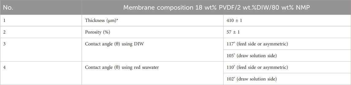
Table 1. A desire characterization of PVDF membranes used in this study.
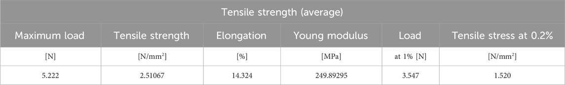
Table 2. Tensile strength of PVDF membrane.
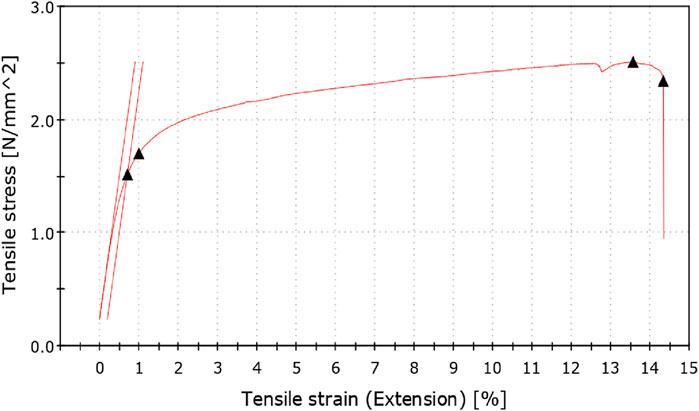
Figure 1. Tensile stress vs. tensile strain of higher molecular weight PVDF membrane.
2.3.1 Experimental setup
The bench-scale unit used in this experiment was fabricated in the Center of Excellence in Desalination Technology (CEDT) and is shown in Figure 2. A comprehensive protocol of the aforementioned bench scale and the uncertainty variables has been published in our earlier studies, and it can be found elsewhere (Hejazi et al., 2019). Figure 3 shows the exploded view photograph of the swirling flow module, and Figures 3, 4 present the comprehensive process configuration of the DCMD swirling flow unit which has been patented (Tarabara and Wiesner, 2003). On the permeate side, the tank was filled with Deionized water (DIW) obtained from Ultrapure Millipore Simplicity water systems. The resistivity of DIW was 18.2 ΜΩ cm at 25°C.
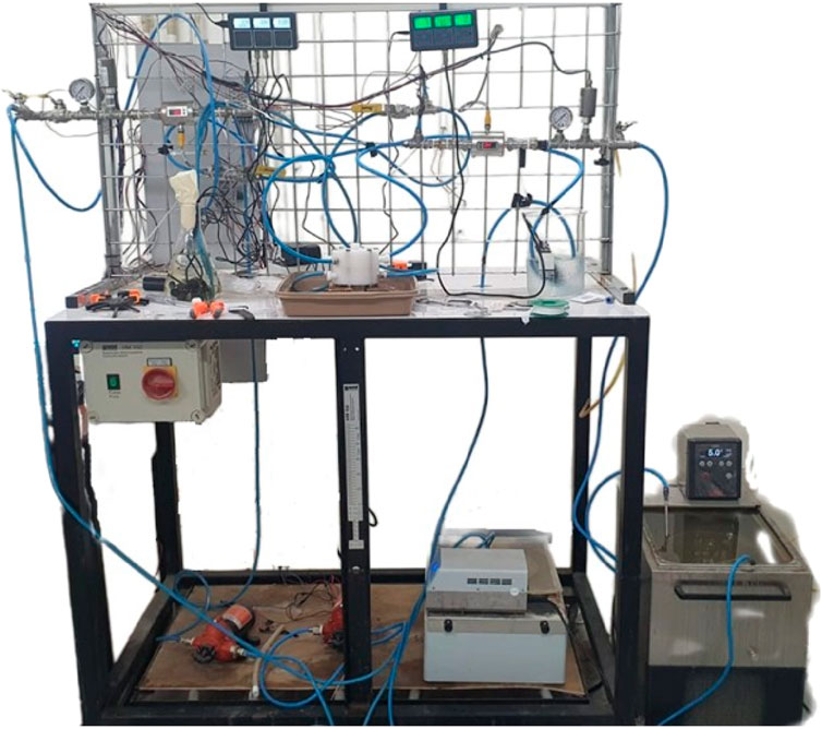
Figure 2. The bench-scale DCMD unit.
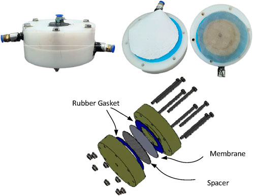
Figure 3. The test module configuration (Abulkhair, 2022).
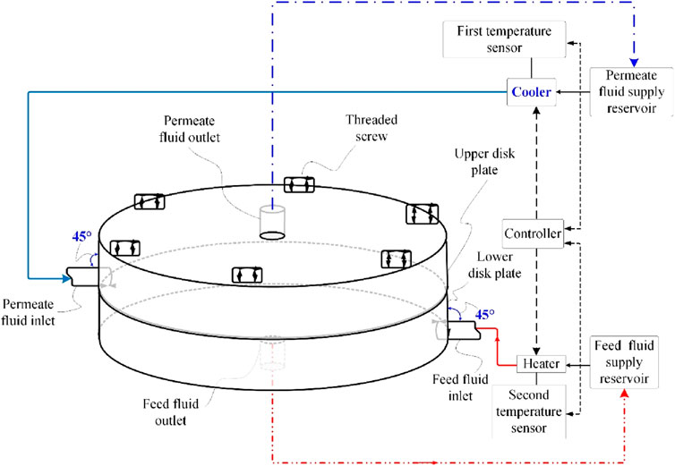
Figure 4. Schematic diagram of process configuration of DCMD swirling flow unit (Abulkhair, 2022).
2.3.2 Experimental procedure
There were two cycles in the experiment: the first cycle consisted of feeding water (a hot stream), and the second cycle consisted of pouring water through (a cool stream). Both cycles were performed using the same apparatus. The hot side received water from the faucet, while the cold side received fresh water that had been properly distilled. Both sides were fed water separately. Before beginning the experiment, the feed and permeate tanks were weighed and recorded. After that, the experiment was brought to a start. A controlled heating bath is used to heat the feedwater before it is introduced into the MD module (Abulkhair, 2022). On the other hand, a controlled cooling bath is used to prevent the permeate water from becoming cold. Additionally, we make use of the water pumps in order to build a link between the MD module and the feed and permeate pumps. This connection is made possible by the water pumps. The electronic balance was utilized to keep a continuous record of the weight of the permeate tank, commencing with the beginning and going all the way through to the ultimate conclusion. Following the distribution of the cold water to the permeate bath, the hot water was transferred back to the feed bath. All of the water that was discharged from the module was brought back to the baths that were designated for it. For the purpose of controlling the flow of water on both sides, two manual flow meters are utilized. In addition, four temperature sensors and four pressure transducers were utilized in order to keep track of the parameters of the process. Each instrument was connected to a data collecting system that was capable of recording data on a minute-by-minute basis. In each of the setups, the experiment was carried out for a duration of 1 hour.
3 Results and dissection
3.1 Characteristics of specified PVDF membrane
To generate the swirling fluid flow pattern, the distance between the feed and draw solution channel and the membrane sandwich was extended by around 7.52 ± 0.1 mm. For this reason, the thickness of a membrane as well as its mechanical strength is an essential parameter to take into consideration when dealing with whirling flow. A micrometer was used to measure the thickness of the PVDF membrane that was specified. This measurement was performed at four different sites on the constructed membrane, and the results were reported according to an average value. In the earlier experiment that we conducted, we employed a PVDF membrane that had a thickness of 200 μm. There is no difference in the membrane’s composition, as illustrated in Table 1. After being subjected to increasing flow rates for both feed and draw solution flows, the membrane broke due to the increased pressure. When considering membrane diffusion from both a technological and economic standpoint, it is generally agreed that membranes with a thickness that falls within the range of 100–200 μm are the most suited. It is possible that decreasing the thickness of the membrane will result in an increase in water recovery; nevertheless, it is essential to retain the membrane’s stability, particularly its thermal stability, in order to guarantee that it will continue to function for an extended period of time. While conducting this investigation, we found that membrane thickness, around 400 μm, significantly impacts swirling flow implementation. Regardless of the flow rate that we utilized during the DCMD application, this scenario is always the case. Table 1 and Figure 1 provide a comprehensive review of the mechanical parameters of the PVDF membranes with a greater molecular weight. These properties include thickness, tensile stress at maximum load, tensile stress at break, modulus, and elongation at break.
In addition, the results of the porosity test are shown in Table 1, which provides an indication of the values that are considered desirable for the composition of the membrane. On the other hand, the fact that there was 2% DIW in NMP made it very clear that the MD membrane had the right amount of porosity. This might be because of the considerable diffusivity of NMP that occurs during the phase inversion process. There is a high probability that the presence of DIW as an additive is responsible for the increased diffusivity of NMP.
A comparison of the relative hydrophobicity values of the PVDF membrane in two distinct fluids is shown in Table 1 and Table shows a tensile strength of higher molecular weight PVDF membrane. These values are ordered according to the different contact angles that are presented. It has been determined that the asymmetric layer of the PVDF membrane that was specified in the feed channel is responsible for the greater contact angle of 117° that was seen in the results. The backside of the membrane, which is also known as the draw solution channel, exhibits a contact angle that is somewhat lower than the contact angle on the other side of the membrane. This contact angle is critical for MD applications. However, when testing the membrane in red seawater, the membrane’s contact angle decreases. The presence of salt in the water is extremely likely to be the source of this phenomenon.
3.2 Evaluation of swirling flow
The purpose of this experimental approach is to evaluate the effectiveness of the direct contact membrane distillation (DCMD) process, with a particular emphasis on the volume of permeation (freshwater) that is produced during a predetermined period of time. In Figure 5, the findings for three distinct fluid rates are presented, and the swirling flow testing cell is used to illustrate the arrangement of two different temperature fluids. The membrane sandwich’s gap measures 0.75 cm from the membrane to the center exit channel of the cell. The 45° curve to 90° vector may be observed, and Figure 5 demonstrates that in both fluids, after traversing the upper opening, it impacts the whole membrane active surface area with consistent velocity. Subsequently, it proceeds to expand, establishing a uniform distribution and continuing to flow in a pattern that is reminiscent of a swirl across the surface of the membrane. Additionally, there is a clear indication of robust fluid circulation on both sides of the fluids respectively. The water permeation and feed concentrate that are created eventually leave the cell through the aperture in the center of the cell. Within the vicinity of the membrane, it is possible to expect that the fluid velocity profiles at the base will improve one’s understanding of the water vapors that are created.
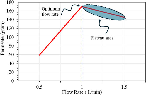
Figure 5. The influence of various flow rates of swirling flow on MD permeation rate.
Nevertheless, From Figure 5, it is clear that increasing the flow rate leads to increases in the amount of permeation produced. This phenomenon is likely due to the enhanced heat transfer that comes with a higher flow rate, which helps to maintain the temperature gradient across the membrane and accelerates the distillation process. Moreover, it has been revealed that the flow direction in both streams is parallel to one another and seems to be perpendicular to the surface of the membrane, respectively. The fluid velocity is seen to be moderate near the cell’s outer surface, which indicates that an upswing zone is present at this particular place. However, at a flow rate of 1.5 L/min, the increase in permeate production becomes less than linear as shown in Figure 5, suggesting that the system may be approaching an optimal flow rate. Beyond this point, the efficiency of heat transfer may begin to plateau. When flow rates are increased, there is a greater degree of concordance between the vortex phenomena and the departure region in both streams. In the event that the flow rate is increased, it has the ability to generate a vacuum on both sides, which may result in a stagnation zone between the two stream flows as a consequence of poor vapor diffusion in the membrane. Shen et al. (2025) were also reported that the tangential flow phenomenon at the membrane surface indicated that the fluid velocity is reduced near the outer wall of the cell, demonstrating the presence of a stagnation zone in the aperture area.
Figure 6 illustrates the penetration rates, which vary depending on the temperature. According to the findings, the temperature difference (∆T) between the feed and permeate sides, in addition to the flow rate, has a significant impact in influencing the quantity of permeate that is produced. A greater temperature difference enhances the vaporization of the feed, subsequently leading to increased permeate production. In considering the data, it appears that bigger temperature variations, such as 40°C and 45°C, produce more favorable circumstances for distillation. On the other hand, the generation of permeate reduces directly in proportion to the decrease in the temperature differential (∆T). This decrease can be due to decreased evaporation rates, which in turn diminish the driving power for the diffusion of vapor through the membrane. During the experiment, we noted specific uncertainties; for instance, at low flow rate, the acceleration of permeate recovery was notably low. The observed phenomenon may be attributed to environmental stability; after approximately 35 min, the permeate recovery exhibited an acceleration of around 30% compared to the initial phase of the experiment. However, at higher flow rates, the acceleration of permeate recoveries demonstrates a significant area of investigation. This demonstrates a favorable alignment in addressing the issue of temperature polarization. The elevated flow rates likely generated a substantial vortex at the feed side, which may enhance the affinity for latent heat of vaporization. Shakaib et al. (2012) has reported that spacer direction influences temperature polarization and heat transmission rates, according to CFD models. Spacer filaments cause limited heat transfer rates due to excessive temperature polarization when they come into contact with the membrane’s top or bottom surfaces. There is less temperature polarization when these filaments are peeled off the membrane.
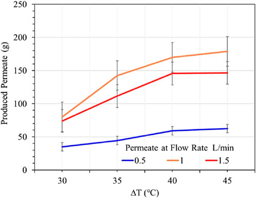
Figure 6. Permeate flux results at various temperatures.
Therefore, the ideal values required for a combination of flow rate and ∆T are contingent upon the particular condition that is being considered. Generally speaking, larger flow rates and higher ∆T values are likely to result in improved performance. However, when the flow rate is increased to greater levels (for example, 1.5 L/min), the rise in permeate becomes less substantial. This suggests that there may be a range that is considered optimal for both variables (flow rate and ∆T).
4 Conclusion
This study evaluates the performance enhancement of direct DCMD modules by utilizing swirling flow configurations at various levels. Turbulence can be generated by employing swirling flow, leading to an increased affinity for latent heat of vaporization, a decrease in temperature polarization (TP), and a reduction in concentration polarization (CP). This process facilitates enhanced heat and mass transfer efficiency. A preliminary experimental DCMD system has been carried out in order to examine the influence that varying permeate flow rates and temperature shifts have on the permeate flux. This decision was made in order to fulfill both of these objectives. The results of the study reveal that, up to a certain point, greater flow rates and temperature differences significantly improve the overall performance of the system that is being considered. The purpose of this study is to emphasize the potential of swirling flow techniques to improve the efficiency and scalability of MD systems. This is done with the intention of enhancing the desalination or treatment of water applications. In an effort to boost the efficiency of the water treatment process, these steps are taken. In spite of this, it is necessary to do a thorough investigation in order to analyze all aspects, notably the relevance of the whirling flow phenomenon at higher temperatures (about 80°C–90°C) and flow levels that are higher than the work that has been provided. In the future, there will also be a computational fluid dynamics (CFD) investigation.
Data availability statement
The raw data supporting the conclusion of this article will be made available by the authors, without undue reservation.
Author contributions
IM: Formal Analysis, Writing – original draft, Writing – review and editing. HT: Data curation, Writing – original draft. IA: Writing – original draft. HA: Funding acquisition, Methodology, Project administration, Supervision, Writing – review and editing. MF: Formal Analysis, Investigation, Resources, Writing – review and editing.
Funding
The author(s) declare that financial support was received for the research and/or publication of this article.
Acknowledgments
This Project was funded by KAU Endowment (WAQF) at King Abdulaziz University, Jeddah, The authors, therefore, acknowledge with thanks WAQF and the Deanship of Scientific Research (DSR) for technical and financial support.
Conflict of interest
The authors declare that the research was conducted in the absence of any commercial or financial relationships that could be construed as a potential conflict of interest.
Generative AI statement
The author(s) declare that no Generative AI was used in the creation of this manuscript.
Publisher’s note
All claims expressed in this article are solely those of the authors and do not necessarily represent those of their affiliated organizations, or those of the publisher, the editors and the reviewers. Any product that may be evaluated in this article, or claim that may be made by its manufacturer, is not guaranteed or endorsed by the publisher.
References
Abulkhair, H. A. (2022). Swirling flow generator for membrane distillation. Publication of US11247177B1.
Ahmed, I., Hussain, A., Hasani, S., Shakaib, M., and Yunus, R. M. (2012). Computational modeling for visualization of flow patterns in a membrane testing device. Sep. Purif. Technol. 90, 1–9. doi:10.1016/j.seppur.2012.02.004
Ashoor, B., Mansour, S., Giwa, A., Dufour, V., and Hasan, S. (2016). Principles and applications of direct contact membrane distillation (DCMD): a comprehensive review. Desalination 398, 222–246. doi:10.1016/j.desal.2016.07.043
Bertelsen, R. A., and Olsen, D. L. (1989). Cross-flow filtration membrane test unit. Publication of US4846970A.
Cortés-Juan, F., Balannec, B., and Renouard, T. (2011). CFD-assisted design improvement of a bench-scale nanofiltration cell. Sep. Purif. Technol. 82, 177–184. doi:10.1016/j.seppur.2011.09.010
Fimbres-Weihs, G., and Wiley, D. (2007). Numerical study of mass transfer in three-dimensional spacer-filled narrow channels with steady flow. J. Membr. Sci. 306 (1–2), 228–243. doi:10.1016/j.memsci.2007.08.043
Geraldes, V., Semião, V., and de Pinho, M. N. (2002). The effect of the ladder-type spacers configuration in NF spiral-wound modules on the concentration boundary layers disruption. Desalination 146 (1–3), 187–194. doi:10.1016/s0011-9164(02)00467-8
Hasani, S., Shakaib, M., and Mahmood, M. (2009). CFD modeling of unsteady fluid flow and mass transfer in spacer-filled membrane modules. Desalination Water Treat. 9 (1–3), 211–220. doi:10.5004/dwt.2009.778
Hejazi, M.-A. A., Bamaga, O. A., Al-Beirutty, M. H., Gzara, L., and Abulkhair, H. (2019). Effect of intermittent operation on performance of a solar-powered membrane distillation system. Sep. Purif. Technol. 220, 300–308. doi:10.1016/j.seppur.2019.03.055
Kawachale, N., Kirpalani, D. M., and Kumar, A. (2010). A mass transport and hydrodynamic evaluation of membrane separation cell. Chem. Eng. Process. Process Intensif. 49 (7), 680–688. doi:10.1016/j.cep.2009.08.001
Kawachale, N., Kumar, A., and Kirpalani, D. M. (2009). A flow distribution study of laboratory scale membrane gas separation cells. J. Membr. Sci. 332 (1–2), 81–88. doi:10.1016/j.memsci.2009.01.042
Li, F., Meindersma, W., De Haan, A., and Reith, T. (2002). Optimization of commercial net spacers in spiral wound membrane modules. J. Membr. Sci. 208 (1–2), 289–302. doi:10.1016/s0376-7388(02)00307-1
Mariam Khan, I., and Al-Ghouti, M. A. (2021). DPSIR framework and sustainable approaches of brine management from seawater desalination plants in Qatar. J. Clean. Prod. 319, 128485. doi:10.1016/j.jclepro.2021.128485
Olatunji, S. O., and Camacho, L. M. (2018). Heat and mass transport in modeling membrane distillation configurations: a review. Front. Energy Res. 6, 130. doi:10.3389/fenrg.2018.00130
Omerspahic, M., Al-Jabri, H., Siddiqui, S. A., and Saadaoui, I. (2022). Characteristics of desalination brine and its impacts on marine chemistry and health, with emphasis on the Persian/arabian gulf: a review. Front. Mar. Sci. 9, 845113. doi:10.3389/fmars.2022.845113
Panagopoulos, A., and Haralambous, K.-J. (2020). Environmental impacts of desalination and brine treatment - challenges and mitigation measures. Mar. Pollut. Bull. 161 (Part B), 111773. doi:10.1016/j.marpolbul.2020.111773
Schwinge, J., Wiley, D., and Fletcher, D. (2002). A CFD study of unsteady flow in narrow spacer-filled channels for spiral-wound membrane modules. Desalination 146 (1–3), 195–201. doi:10.1016/s0011-9164(02)00470-8
Shakaib, M., Hasani, S., Ahmed, I., and Yunus, R. M. (2012). A CFD study on the effect of spacer orientation on temperature polarization in membrane distillation modules. Desalination 284, 332–340. doi:10.1016/j.desal.2011.09.020
Shen, J., Wang, X., Zhu, X., Tang, B., Liu, C., Li, W., et al. (2025). Scaling in reverse osmosis seawater desalination: mechanism and prevention—a literature review. Can. J. Chem. Eng. 103 (2), 503–523. doi:10.1002/cjce.25427
Stillwell, A. S., and Webber, M. E. (2016). Predicting the specific energy consumption of reverse osmosis desalination. Water 8 (12), 601. doi:10.3390/w8120601
Suleman, M., Asif, M., and Asad Jamal, S. (2021). Temperature and concentration polarization in membrane distillation: a technical review. Desalination Water Treat. 229, 52–68. doi:10.5004/dwt.2021.27398
Tarabara, V. V., and Wiesner, M. R. (2003). Computational fluid dynamics modeling of the flow in a laboratory membrane filtration cell operated at low recoveries. Chem. Eng. Sci. 58 (1), 239–246. doi:10.1016/s0009-2509(02)00436-0
Tayeh, Y. A., Alazaiza, M. Y. D., Alzghoul, T. M., and Bashir, M. J. K. (2025). A comprehensive review of RO membrane fouling: mechanisms, categories, cleaning methods and pretreatment technologies. J. Hazard. Mater. Adv. 18, 100684. doi:10.1016/j.hazadv.2025.100684
Keywords: membrane distillation, configurations, DCMD, swirling flow, TP
Citation: Moujdin IA, Totah HS, Allaf I, Abulkhair H and Fayed M (2025) Evaluation of swirling flow phenomenon in direct contact membrane distillation. Front. Mech. Eng. 11:1569918. doi: 10.3389/fmech.2025.1569918
Received: 02 February 2025; Accepted: 31 March 2025;
Published: 28 April 2025.
Edited by:
Eswaramoorthy Muthusamy, Shri Mata Vaishno Devi University, IndiaReviewed by:
Cetin Canpolat, Çukurova University, TürkiyeSeyed Borhan Mousavi, Texas A and M University, United States
Copyright © 2025 Moujdin, Totah, Allaf, Abulkhair and Fayed. This is an open-access article distributed under the terms of the Creative Commons Attribution License (CC BY). The use, distribution or reproduction in other forums is permitted, provided the original author(s) and the copyright owner(s) are credited and that the original publication in this journal is cited, in accordance with accepted academic practice. No use, distribution or reproduction is permitted which does not comply with these terms.
*Correspondence: Hani Abulkhair, aGFib2Fsa2hhaXJAa2F1LmVkdS5zYQ==