 Lis Corral-Gómez1
 Octavio Armas1*
 Francisco Moya-Fernández1
 José A. Soriano1
 Francisco J. Martos2
 José Nogueira1
- 1Universidad de Castilla-La Mancha, Campus de Excelencia Internacional en Energía y Medioambiente, Escuela de Ingeniería Industrial y Aeroespacial, Instituto de Investigación Aplicada a la Industria Aeronáutica, Toledo, Spain
- 2Universidad de Málaga, Escuela de Ingenierías Industriales, Málaga, Spain
The evolution of the main macroscopic parameters that characterize spray formation for three different fuels is studied by means of the Schlieren visualization technique. The annalized fuels comprise a fossil diesel fuel, used as reference, and two neat low carbon liquid 100% paraffinic fuels: a gas-to-liquid (GtL) and a hydrotreated vegetable oil (HVO). Additionally, the paper exposes the behavior of fuels autoignition for different injection pressures and start of energizing (SoE), for prescribed thermodynamic variables inside the engine cylinder. The experimental results obtained at the beginning of the injection process are compared with results from known models of penetration and cone angle of the fuel spray under non-evaporative conditions. These conditions are chosen to match those of the diesel engines used in surveillance light aircraft such as small helicopters. This work presents two important novelties: (i) the application of an automatic image analysis procedure (previously published) to the fuel injection process and (ii) the comparison of different fuels, regarding their effect on the injection process and the start of combustion. This is done under complete replacement of fossil fuel by two 100% paraffinic fuels. The most important results are the following: i) Compared to GtL and Diesel fuels, the HVO fuel has shorter ignition delay. This result could be attributed to its higher cetane number. ii) However, in most of the tested cases, in addition to a slightly longer spray penetration of the HVO fuel, its cone angle is also slightly wider than that of the other two fuels. This result would be collaborating in the development of a wider spray surface during the evolution of the spray lift off and beyond. This leads to a better air entrainment, and, in consequence, to produce an additional shortening of the ignition delay compared to the other two fuels. These findings would facilitate the fine tuning of modern engine technology for a progressive introduction of mentioned low carbon fuels in light aircraft such as unmanned helicopters for surveillance.
1 Introduction
Along the last years, small and medium size helicopters, used as surveillance unmanned aerial vehicles, have been powered by reciprocating internal combustion engines, i.e., aviation piston engines (Ning et al., 2020). In military applications, UAV engines have required not only high-power performance, but also high levels of stability and safety for tasks such as of intelligence, surveillance, and reconnaissance (ISR) missions (Schihl et al., 2015; Jing et al., 2015). Aviation piston engines have two modes of combustion: compression ignition (CI) and spark ignition (SI). These engines are undergoing a transition from gasoline to heavier fuels such as diesel due to its low volatility, high viscosity, and greater safety in storage and transportation; shifting from SI to CI (Chen et al., 2017; Ning et al., 2019).
Since the early 2000s diesel piston engines have been introduced in the aeronautical market. Their main advantage being the possibility to use aviation kerosene like Jet A1 instead of Avgas (aviation gasoline, like 100LL) and an smaller specific fuel consumption. This means double economical savings using less expensive fuel and at smaller quantities. Soon the flying schools accepted these engines to power their light aircrafts like the Cessna 172. Although helicopter stationary flight demands higher power than airplanes, these engines have evolved increasing their power to weight ratio and start to be an option for light helicopters. This interest triggered the study presented in this paper. Additionally, in the near future, the possibility of using diesel engines for small helicopters is going to meet further requirements. The European aeronautical regulations are forcing a shift from fossil fuel to SAF (Sustainable Aviation Fuels), carbon neutral. EASA (European Union Aviation Safety Agency) has imposed on European airlines to include a minimum content of 2% of SAF in their fuel for 2025, 6% in 2030 and 70% in 2050. This means that engines conceived for using aviation kerosene should also foresee the possibility of using SAFs like the HVO or Power to Liquid fuels. In this paper GtL is tested as an available precursor of Power to Liquid and HVO as a SAF by itself.
When diesel fuel is burned inside compression ignition engines, substances are generated that are harmful to the environment and to people’s health (Dinc and Otkur, 2021; Arkoudeas et al., 2003; Gowdagiri et al., 2014). Nitrogen oxides (
HVO is a sustainable renewable fuel obtained through the hydrotreatment and isomerization of fatty organic waste. This fuel is made up of a group of paraffinic hydrocarbons with no sulfur or aromatic content. This leads to a reduction of
GtL is a fuel synthesized from natural gas through the Fisher-Tropsch process (Amhamed et al., 2024). This fuel is sulfur free, its amount of aromatic compounds is negligible and the proportion of carbon to hydrogen is lower, leading to a decrease in the formation of soot (Schaberg et al., 2005). Like HVO fuel, GtL fuel has less ignition delay than diesel due to a lower density and a higher CN. These particular properties mean that the generation of CO,
To successfully employ sustainable paraffinic fuels in current and future thermal engines, it is essential to study the development of the fuel spray under conditions as close as possible to those of the combustion chamber where it will be injected. From a macroscopic perspective, the development of the spray cone angle and its penetration into the combustion chamber are parameters that define the air entrainment process during spray lift off. This affects the air-fuel mixing process and, consequently, the combustion process. Finally, the effectiveness of the combustion process simultaneously determines the engine’s performance level and the regulated pollutant emissions generation. This reality is a fundamental factor for studying the fuel sprays and for contributing to determine the viability of using new fuels, Gopinath et al. (2020).
The fuel spray characteristics of different fuels differ from each other because the physical properties of the fuels are different (Hulkkonen et al., 2011; Geng et al., 2021). Kook and Pickett (2012) studied spray macroscopic parameters such as spray penetration and cone angle for diesel and GtL fuels in a constant volume chamber. The experimental tests were carried out under similar operating conditions to those found in a compression ignition engine. As a result, the authors obtained a lower spray penetration for the GtL fuel compared to the diesel fuel. This could be due to the faster evaporation characteristics of the GtL fuel. Choi et al. (2015) also studied the spray macroscopic parameters of GtL and diesel fuels in a compression ignition engine and determined that the cone angle of GtL fuel was larger than that of diesel fuel. Bohl et al. (2017) determined the macroscopic parameters of the HVO fuel spray and compared it with diesel fuel. During experimental tests, the authors heated the fuels to 80
The objective of this work is to contribute to determining the spray macroscopic parameters and the ignition delay of HVO, GtL and diesel fuels. It is also important to evaluate the spray surface interface with the surrounding air inside the combustion chamber. To achieve this, an experimental facility based on a CI engine with optical accesses is used. It allows visualizing the injection and combustion process. The Schlieren optical technique is used to acquire images of the fuel injection event and its subsequent combustion. The experimental tests are carried out at different injection pressures and different injector starts of energization (SoE), to determine their influence (i) on the macroscopic parameters, (ii) on the ignition delay and (iii) on the spray surface.
2 Materials and methods
2.1 Experimental facility
This work is part of a larger research project. Figure 1 presents the complete methodological statement of the whole project, highlighting the particular objective of the part published in this manuscript. The relevant parts of experimental installation used in this manuscript are described along the following text.
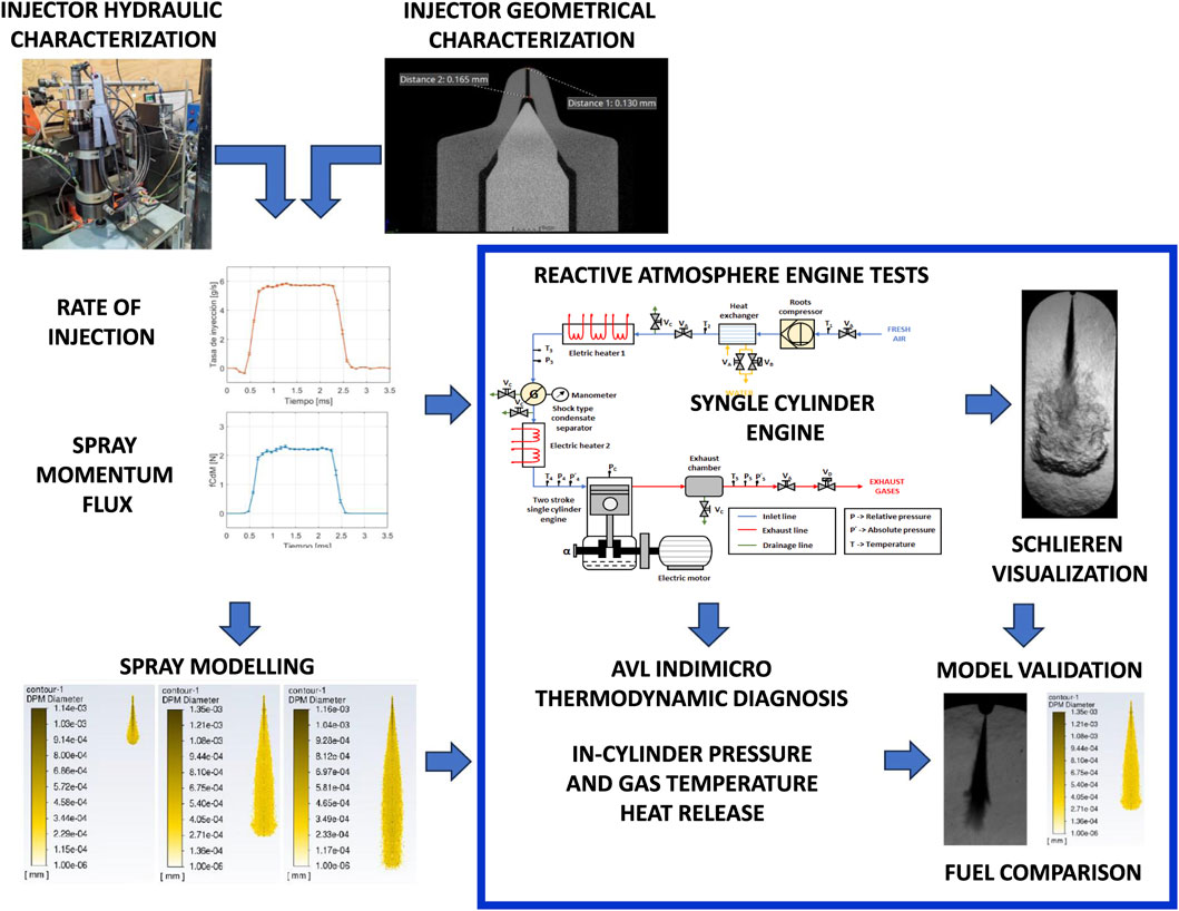
Figure 1. Scheme of the spray visualization study approach with different fuels (framed in red color) and the fuel spray evolution comparison, objective of the present work (framed in blue color).
In an actual CI engine, the length of the diesel spray is determined by either (i) the diameter of the pre-combustion chamber (in an indirect injection combustion engine) or (ii) the piston bowl (in the case of direct injection combustion engines). This length, for an automotive engine, can measure between 18 and 50 mm before hitting the wall. However, in most cases, the spray hits the bowl wall before the atomization process is complete. This is the reason why it is important to study the jet lengths up to 100 mm, a length long enough for the jet to complete its atomization.
The engine used in this work is an adapted version of a Jenbach JW-50 two-stroke, single-cylinder diesel engine with 3 L displacement, with cylinder diameter of 150 mm; geometrical stroke of 170 mm; effective stroke of 108 mm, total original geometric compression ratio of 26.3
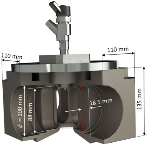
Figure 2. Modified engine cylinder head for fuel spray visualization (selected dimensions indicated).
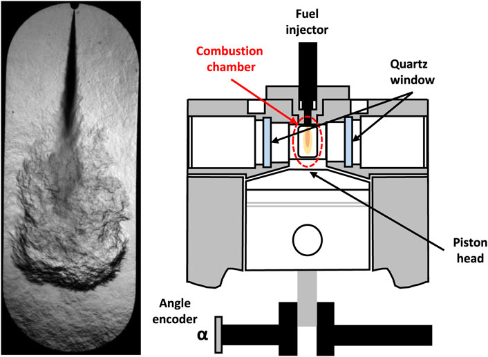
Figure 3. Left
The operating conditions have been chosen to be representative of the ones related to aeronautical diesel engine. A usual matching is made by assuring just the same air density, as this matchs many processes (e.g., Equation 1). But, in this study, the parameters involving spray formation and evolution force the matching of the whole thermodynamical state (i.e., Temperature and Pressure). The conditions selected span from one extreme case (a) corresponding to 2.82 MPa and 778 K for SOE at 4° before TDC; down to the other limit case (b) of 1.88 MPa and 693 K for SOE at 18° before TDC. Regarding these conditions, a basic comparison can be made with those meet in a typical aeronautical Diesel engine like CD-135 (based on the Mercedes-Benz OM640), that powers aircrafts up to a service ceiling of 24,000 feet (7,315 m). This engine is characterized by SOE around 15.7° before TDC, geometrical compression ratio of 18:1 and supercharger pressure ratio of 2:1. Measurements of the indicated cycle (Mihyar et al., 2023) indicate that the effective compression ratio from the environment to the SOE event is: 47.8. Thus, the commented case (a) corresponds to the operation of this engine at an altitude of 13,900 ft (4,236 m) and ISA -6 (6° below the International Standard Atmosphere). This is a common condition for flying over USA or Middle Europe. While the commented case (b) corresponds to an altitude of 23,700 ft (7,223 m) and ISA – 33. An extreme condition, usual if flying over Canada or North Europe in winter. Cold cases have been selected as they compromise engine functioning to a higher degree than hot ones.
During the experimental tests the engine speed
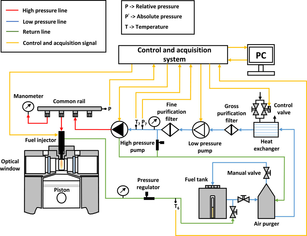
Figure 4. Scheme of the independent fuel injection system.
Thermodynamic diagnosis was carried out using an AVL IndiMicro 602 (which includes an in-cylinder pressure sensor GH14P and its glow plug adaptor) and an AVL IndiCOM 2013 (2.5) system for combustion analysis. Crankshaft rotational speed and instantaneous piston position were determined by means of an angle encoder (Kistler 2614CK) with a resolution of 720 pulses per revolution (0.5 crank angle degree), (Martos et al., 2023).
2.2 Visualization system and image processing
The visualization system used in the experimental facility is the Schlieren optical technique. This technique allows the detection of the variation of the density gradients of an in-homogeneous and transparent medium (Settles, 2001). The Schlieren system setup, presented in Figure 5, is divided into two sections: lighting and collection. The lighting section comprises a 150 W lamp, a focusing lens of f = 50.3 mm and a parabolic mirror of f = 1,000 mm. The light source (lamp and focusing lens) is located at the focal point of the parabolic mirror, forming an array or parallel light beams. The collection section comprises another parabolic mirror of f = 1,000 mm and a Fastcam nova S6 high-speed camera. The parabolic mirror colects the light and focuses it on the high-speed camera.
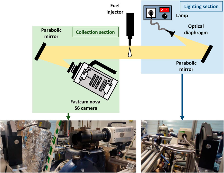
Figure 5. Scheme of the used Schlieren system and views of the mounting on the engine.
The control software allows to synchronize the acquisition of the images of the fuel spray and the injection event. To do this, based on the crankshaft angle, the software sends a trigger signal to the high-speed camera and the fuel injector. In each experimental test, 100 images are taken, of which 10 of them are taken before the injection and 90 of them afterwards. 5 repetitions were made for each experimental test to reduce the uncertainty due to the natural engine cyclic dispersion. The images taken have a depth of 12 bits, so 0 is represented as black color and 4,095 as white color. Table 1 shows the configuration of the parameters of the high-speed camera used for the experimental tests.
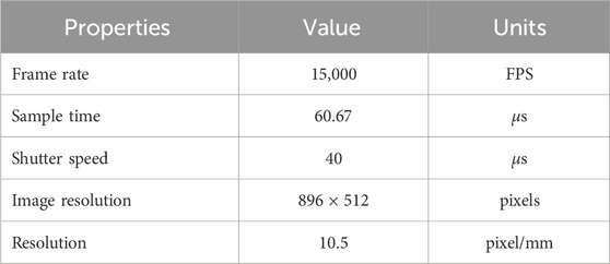
Table 1. Configuration of the parameters of the high-speed camera used for the experimental tests.
The image processing technique used, is suitable for studying the macroscopic parameters of the fuel spray (Soid and Zainal, 2011). It has been applied with the help of an algorithm developed in
Figure 6 shows a schematic example of the procedure followed for determination of the main macroscopic parameters such as: spray penetration, cone angle and estimated spray surface using the automatic procedure previously published in Corral-Gómez et al. (2023b) and commented in Section 3 of the present work. In addition, the mentioned procedure also helps to automatically determine the start of injection and the ignition delay from the image analysis. The present work constitutes a direct application of the above cited methodology.
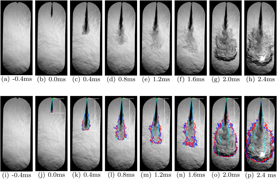
Figure 6. Schematic example of the procedure followed for determination of the main macroscopic parameters presented in subsections 3.1, 3.2, and 3.3. Spray contour (blue), position of the injector (green), estimated symmetrical spray contour (red), limits of the spray cone angle (cyan) and spray penetration (white). (a) −0.4 ms (b) 0.0 ms (c) 0.4 ms (d) 0.8 ms (e) 1.2 ms (f) 1.6 ms (g) 2.0 ms (h) 2.4 ms (i) −0.4 ms (j) 0.0 ms (k) 0.4 ms (1) 0.8 ms (m) 1.2 ms (n) 1.6 ms (0) 2.0 ms (p) 2.4 ms.
2.3 Spray penetration and cone angle models
The spray atomisation process depends on variables of the conditions in the combustion chamber, the injection conditions (Corral-Gómez et al., 2023c) and the fuel (Martos et al., 2022). The thermophysical properties of the fuel, such as density and viscosity, significantly affect the flow of the fluid in the injector and consequently the formation of the spray (Martos et al., 2022).
As it is commented in the results section, the first instants of the experimental evolution of the penetration and cone angle of the sprays for the different studied fuels are compared with the evolution predicted by known models proposed under non-evaporative conditions. The models used for the aforementioned comparison are described below.
Desantes et al. (2006) proposed a model to determine the transient spray penetration in a non-evaporative and quiescent environment as a function of the momentum flux,
From an experimental fitting, Desantes et al. (2006) proposed a value of the proportionality constant
In Corral-Gómez et al. (2023c) a correlation of the discharge coefficient as a function of injection pressure,
Considering phenomena such as cavitation or velocity profile, the fuel velocity at the nozzle exit can be a function of the theoretical velocity,
Substituting Equations 3, 4 into Equation 1 and grouping all constants and coefficients into
In Equation 5, the discharge coefficient defined in Equation 3 is used. Additionaly, both the pressure and the density of the gas inside the combustion chamber have been considered to be transient, using their variation to calculate the corresponding increments of
Siebers (2009) proposed a model to determine the spray cone angle,
In Equation 6 the constant
The constant
The validation of the models used in this work, usually employed with fossil diesel fuel, are described in detail in Desantes et al. (2006). However, to be able to use these models with HVO and GtL fuels, parameters such as fuel bulk modulus, fuel injection rate, and/or spray momentum flux have been experimentally validated in previous works (Armas et al., 2016; Payri et al., 2020; Corral-Gómez et al., 2023a) respectively. Also, they have been previously applied to modeling works such as Martos et al. (2022), Corral-Gómez et al. (2023c).
2.4 Fuels
As commented in the introduction, in this study, three fuels have been considered to carry out the experimental tests. The fuels are a HVO fuel supplied by Repsol (Spain), a GtL fuel supplied by SASOL (South Africa) and obtained through a Fischer-Tropsch process, and a conventional fossil diesel fuel without any biodiesel addition, supplied by Repsol (Spain). The last one is used as reference fuel in this work. The main physicochemical properties of fuels are detailed in Table 2. The tested fuels can be used in Diesel engines with application in propulsive systems for land transport, Soriano et al. (2019).
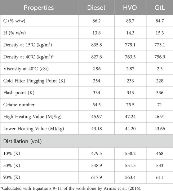
Table 2. Main properties of the tested fuels.
2.5 Test matrix
Table 3 shows the general experimental conditions for the engine used along the test matrix, to obtain the spray macroscopic parameters, the estimation the spray surface and volume, and the ignition delay (ID) and the injector opening delay (IOD). Table 4 shows the experimental conditions for the fuel injection system. The three fuels were operated under four injection pressures, one injection duration and one temperature. The intake air temperature and pressure during all the experimental tests were kept constant. The start of energization (SoE) is set to −4, −6, −8, −10, −12, −14, −16 and −18° from top dead center (TDC).
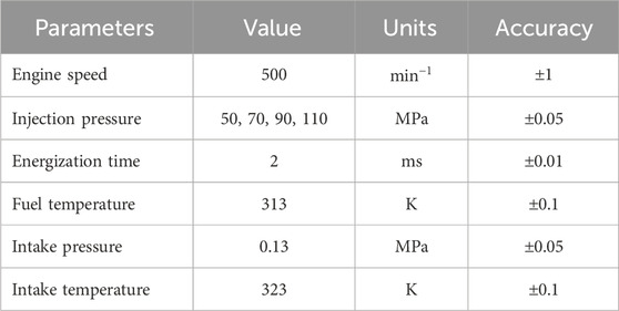
Table 3. Test conditions of the experimental facility.
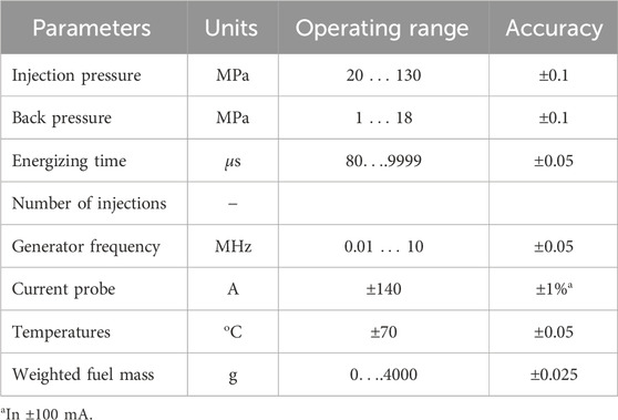
Table 4. Accuracy and uncertainty of measured parameters during the fuel injection tests.
The injector used for the experimental tests is a Bosch solenoid injector with serial number 89909/0445110239, with a single-hole axial nozzle of 0.115 mm and a K-factor of 3.5. All the parameters of the experimental conditions are modified through the control system of the experimental facility.
3 Results and discussion
This section is divided into four subsections. Subsection 3.1 exhibits the results of the spray macroscopic parameters: spray penetration and cone angle of fuels. Subsequently, subsection 3.2 shows the results of the estimation of the spray surface determined for each of the experimental tests. Subsection 3.3 exposes the results for the ignition delay. As commented before, for all fuels, the results shown were calculated as the average all fuels and for the five injection events of each experimental test. The standard deviation of the individual measurements is also displayed for each calculated value and is shaded in the same color. After these results have been exposed, subsection 3.4 indicates de coherence between existing models and the experiments.
3.1 Experimental spray macroscopic parameters: spray penetration and cone angle
Figure 7 shows the spray penetration as a function of crank angle for each fuel. The results shown correspond to injection pressures of 50 and 110 MPa and to a start of energization (SoE) of −4 and −18°.
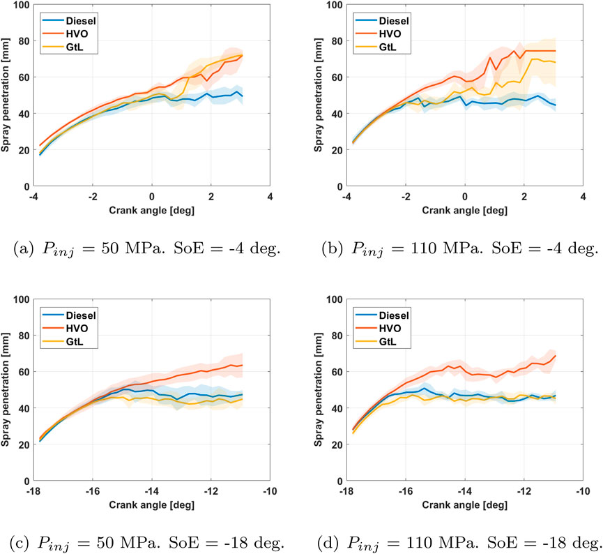
Figure 7. Spray penetration as a function of crank angle for each fuel.
Figure 7 shows that increasing the injection pressure produces a greater impulse of the fuel spray and results in a reduction of the stabilization time for the spray penetration. This behavior is similar to that reported in the literature by Han et al. (2017), Algayyim and Wandel (2021) and ul Haq et al. (2023). On the other hand, an earlier start of energization (SoE) results in the GtL fuel penetration being sharply reduced and behaving the same as diesel fuel. This is due to the low density and surface tension of the GtL fuel and the reduction in the ambient density inside the cylinder as the start of energization (SoE) advances. A greater ambient density, a lower density and surface tension of the fuel favors better atomization of the fuel, and therefore greater penetration of the vapor phase of the spray. Besides, the distillation curve of GtL fuel is lower than that of diesel fuel and HVO fuel, so its evaporation is greater than that of these two fuels at the same temperature. This conclusion is consistent with the study carried out by Mancaruso et al. (2011). Finally, the penetration of diesel fuel and HVO fuel is hardly influenced by the modification of the start of energization (SoE).
Figure 8 shows the spray cone angle as a function of crank angle for each fuel. The results shown correspond to the injection pressures of 50 and 110 MPa and to a start of energization (SoE) of −4 and −18°.
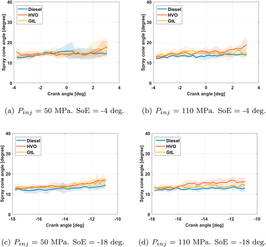
Figure 8. Spray cone angle as a function of crank angle for each fuel.
Figure 8 shows that the spray cone angle is not influenced by the injection pressure, nor by the start of energization (SoE), nor by the properties of the fuel. In all experimental tests, a constant and very similar spray cone angle is obtained between the three fuels. This is because the spray cone angle is influenced by the injector geometry and not by the injection parameters and fuel properties as determined in the work done by Fajri et al. (2023).
The differences in fuel properties obtained, while suggesting that the engine setup can be improved by fine-tuning, would not imply changing its original technology as has occurred in other studies but with other objectives, (Milojević et al., 2024).
The database obtained constitutes a novel contribution to the development, introduction and fine-tuning of new paraffinic fuels in the current propulsion systems used in different means of land, sea and even air transport. Indeed, experimental studies such as the one presented here generate a large amount of data. To make the most of this information, future work will employ statistical analysis techniques such as TOPSIS or Taguchi. These have already been used in the optimization of tribology studies of thermal engines, (Gajević et al., 2024).
Likewise, the management of the experimental information obtained in this work would allow the development of prediction models using techniques such as artificial intelligence or machine learning, (Marinković et al., 2024).
3.2 Estimation of spray surface
Air-fuel mixture performance is usually evaluated with the macroscopic parameters of the spray: the spray penetration and the cone angle of the fuel (Agarwal et al., 2013). With these two parameters the area of the spray is obtained. If a 180° rotation vertical of the spray area is made around the injection axis, the estimate of the spray volume is obtained. This volume has an external surface that is in direct contact with the air in the combustion chamber (Corral-Gómez et al., 2023b). Therefore, the larger the spray surface, the greater the contact with the air, and therefore, the greater the air-fuel mixture, the better the combustion will be and the fewer emissions will be emitted (Hansen et al., 2005). Figure 9 shows the estimation of the spray surface as a function of crank angle for each fuel. The results shown correspond to the injection pressures of 50 and 110 MPa and to a start of energization (SoE) of −4 and −18°.
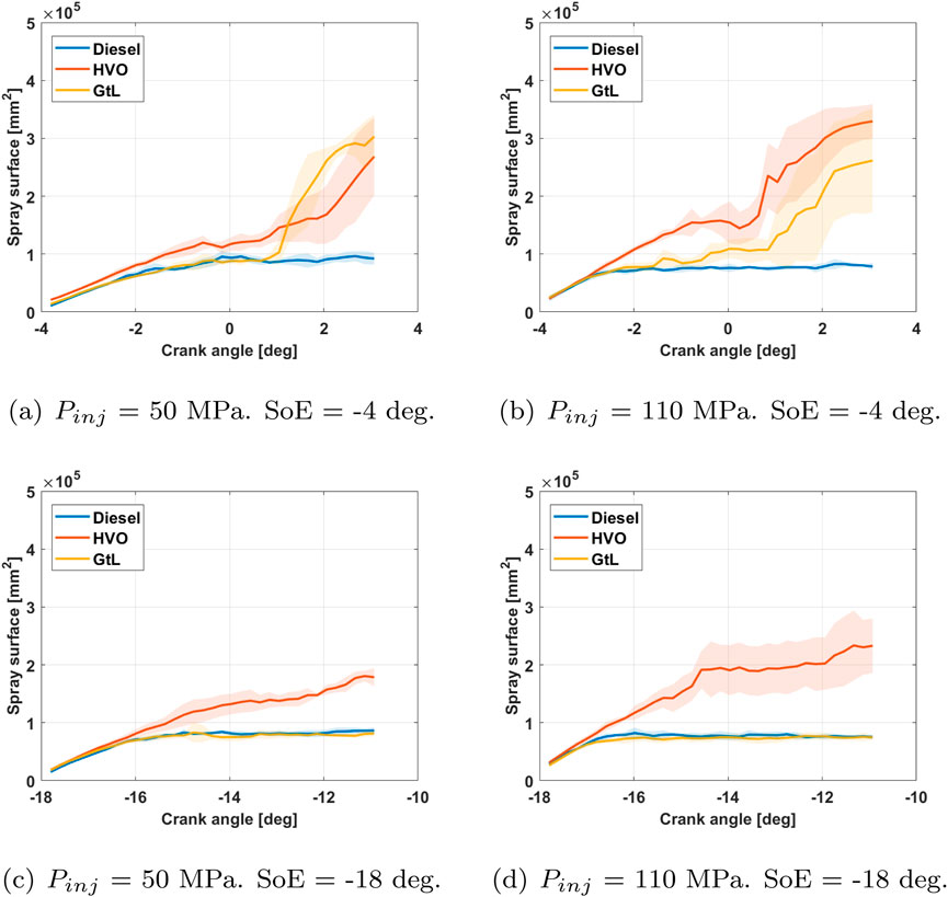
Figure 9. Estimation of the spray surface as a function of crank angle for each fuel.
Figure 9 shows that the spray surface has the same behavior as the spray penetration because the spray angle remains constant for the same injector geometry.
3.3 Estimation of ignition delay
The ignition delay is an important parameter which characterizes the initiation of the combustion process and consequently its development in Diesel engines. This parameter depends on fuel chemical characteristics, related to the fuel structure and its properties (chemical delay). It also depends on the thermodynamic engine operating conditions, related to physical processes such as fuel evaporation and mixing with surrounding air (physical delay). Although the main objective of this work is not the determination of ignition delay of the analized fuels, an estimation of this parameter is done. To know and control the fuel ignition delay is important for maximizing the indicated engine work (with penalizing combustion noise) and for minimizing the nitrogen oxides without penalizing the particulate matter emissions (Miron et al., 2021).
Figure 10 shows the start of injection (SoI) and the start of combustion (SoC) as a function of the start of the energization (SoE) comparing the three fuels for each injection pressure.
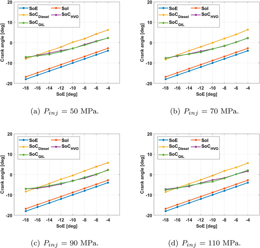
Figure 10. Start of energization (SoE), start of injection (SoI) and start of combustion (SoC) as a function of the start of the energization (SoE) comparing the three fuels for each injection pressures.
Figure 10 shows that the start of injection (SoI) does not vary in any of the experimental tests carried out, so neither the injection pressure nor the start of energization (SoE) influence the injector opening delay (IOD). Regarding the start of combustion (SoC) both paraffinic fuels show differences with the fossil fuel. According to the results presented in Figure 10, for very advanced injection starts (−18°) and any of the injection pressures tested, the time between the start of injection (SoI) and the start of combustion (SoC) (assumed as “ignition delay”) was the same regardless of the fuel used. However, as the injection approaches the minimum of the in-cylinder volume (top dead center), the higher cetane number of the paraffinic fuels caused a significant reduction in the time between SoI and SoC when compared to diesel fuel, and similar for both of them. As can be seen, the automatic procedure is able to detect the different evolution of the “ignition delay” between Diesel fuel (with CN = 51) and both renewable fuels (with CN 75.5 and 71 for HVO and GtL respectively). In this case, the average relative difference between CN of Diesel fuel versus renewable fuels is around 44%. On the other hand, the relative difference in CN between both renewable parafinic both fuels is only around 6%.
Figure 10 also shows, that the injection pressure was modified from 50 to 110 MPa (with a relative difference around 54%). With this magnitude of injection pressure variation, for all the injection advances and fuels tested, it was expected that the ignition delay would decrease as the injection pressure increases and the injection advance is reduced with respect to the TDC (Chen et al., 2024). However, the results in Figure 10 do not show this trend. This behaviour would be explained as follows: i) in the range of injection pressure tested, with this type of engine, the effect of cetane number of fuels on ignition delay, seems to be more important than the effect of the injection pressure itself, and ii) the automatic procedure does not have sensibility enough to clearly detect variations in ignition delay in the range corresponding to the injection pressure variation tested. In any case, similar behaviour was reported by Bjørgen et al. (2020) and Aradi and Ryan (1995).
3.4 Spray penetration and cone angle. modelled and experimental comparison
For each fuel, Figure 11 shows the results obtained with the Equation 5 (dashed line) compared to the experimental results (solid line), for the tested extreme cases of injection pressure and SoE. Note that the model shown in Equation 5 of Desantes et al. (2006) considers that the spray is non-evaporative, the combustion chamber environment is at rest, the spray momentum is constant in time and the radial velocity distribution is Gaussian. Also, the cone angle model proposed by Siebers (2009), shown in Equation 6, considers the combustion chamber environment at rest.
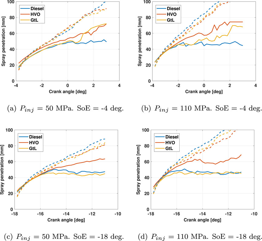
Figure 11. Experimental (solid line) and modelled (dashed line) spray penetration as a function of crank angle for each fuel. (a) Pinj = 50 MPa, SoE = -4 deg, (b) Pinj = 70 MPa, SoE = -4 deg, (c) Pinj = 90 MPa, SoE = -8 deg, (d) Pinj = 110 MPa SoE = -18 deg.
It can be noted that the model results are consistent with experimental measurements for a short time after SoI where the portion of the jet that has vapourised is negligible.
Figure 12 shows how the results obtained with Equation 6 are of the same order as the experimental ones. It also indicates that the dispersion of the results is small. The experimental mean spray cone angle is lower for diesel, higher for HVO fuel and intermediate for GtL fuel.
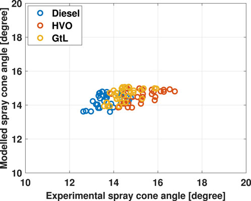
Figure 12. Modelled vs experimental spray cone angle.
This is a very interesting result. On the one hand, the model also predicts the effect of fuel properties on the evolution of the spray cone angle, although with a narrower range (between 13.5 and 15° in modelling) while experimental results are between 12.5 and 17°. On the other hand, although the ignition delay clearly correlates with the cetane number of fuels (higher cetane number leads to shorter ignition delay), the model result helps to confirm the order in ignition delay of fuels tested.
However, at the same in-cylinder thermodynamic conditions, a slightly wider cone angle is modelled and experimentally observed with HVO fuel. A slightly wider cone angle of the HVO fuel spray could be leading to a slightly higher air entrainment. This last fact could be collaborating in an additional shortening of the HVO fuel ignition delay.
4 Conclusions and future works
In this study, the spray macroscopic parameters, ignition delay and the estimation spray surface of HVO, GtL and diesel fuels have been determined. This has been achieved at an experimental facility with a compression ignition engine with optical access that allows the injection and combustion processes to be visualized. Schlieren optical technique produces images able to provide quantitative information. The experimental tests were carried out at different selected injection pressures and different starts of injector energization (SoE) times. The main conclusions obtained are summarized below.
HVO fuel exhibits better air-fuel mixture capabilities than the other two fuels. Since it shows a larger spray surface for all injection pressures and all start of energization (SoE) times. Furthermore, later start of injector energization results in shorter ignition delay and earlier start of combustion. The measurement of the variation of spray evolution with the conditions within the cylinder and the fuel used, allow for a better tuning of the injector start of energizing and to assess the need of swirl in the intake valve port for a better fuel-air mixing. These details are relevant in the optimization of the power to weight ratio that determines the performance of the aircraft.
The work done, and here presented, will be extended to: i) fuel blends composed by renewable sustainable kerosenes and fossil diesel fuels, ii) other different thermodynamic engine conditions coupling to the engine an altitude simulation machine, and iii) the complete spray evolution, comparing it to model predictions under different evaporative conditions.
Data availability statement
The raw data supporting the conclusions of this article will be made available by the authors, without undue reservation.
Author contributions
LC-G: Data curation, Formal Analysis, Investigation, Software, Validation, Visualization, Writing – original draft, Writing – review and editing. OA: Conceptualization, Funding acquisition, Methodology, Project administration, Resources, Supervision, Writing – original draft, Writing – review and editing. FM-F: Data curation, Formal Analysis, Software, Visualization, Writing – original draft, Writing – review and editing. JS: Data curation, Investigation, Methodology, Validation, Visualization, Writing – original draft, Writing – review and editing. FM: Data curation, Formal Analysis, Methodology, Software, Validation, Writing – original draft, Writing – review and editing. JN: Writing – original draft, Writing – review and editing, Supervision, Funding acquisition, Resources.
Funding
The author(s) declare that financial support was received for the research and/or publication of this article. Financial support provided by the Castilla-La Mancha Government to the project, EXPLORA Ref. SBPLY/23/180225/000151. Financial support provided by the Ministry of Science and Innovation to the project LOOK-AHEAD Ref. PID2020-118387RB-C32.
Acknowledgments
Authors also wish to thank the colaboration of SASOL company and REPSOL Tech Lab for the supply of GTL and HVO fuels respectively.
Conflict of interest
OA reports that financial support was provided by Castilla-La Mancha Government.
The remaining authors declare that the research was conducted in the absence of any commercial or financial relationships that could be construed as a potential conflict of interest.
Generative AI statement
The author(s) declare that no Generative AI was used in the creation of this manuscript.
Publisher’s note
All claims expressed in this article are solely those of the authors and do not necessarily represent those of their affiliated organizations, or those of the publisher, the editors and the reviewers. Any product that may be evaluated in this article, or claim that may be made by its manufacturer, is not guaranteed or endorsed by the publisher.
References
Aatola, H., Larmi, M., Sarjovaara, T., and Mikkonen, S. (2009). Hydrotreated vegetable oil (HVO) as a renewable diesel fuel: trade-off between NOx, particulate emission, and fuel consumption of a heavy duty engine. SAE Int. J. Engines 1, 1251–1262. doi:10.4271/2008-01-2500
Agarwal, A. K., Srivastava, D. K., Dhar, A., Maurya, R. K., Shukla, P. C., and Singh, A. P. (2013). Effect of fuel injection timing and pressure on combustion, emissions and performance characteristics of a single cylinder diesel engine. Fuel 111, 374–383. doi:10.1016/j.fuel.2013.03.016
Algayyim, S. J. M., and Wandel, A. P. (2021). Macroscopic and microscopic characteristics of biofuel spray (biodiesel and alcohols) in CI engines: a review. Fuel 292, 120303. doi:10.1016/j.fuel.2021.120303
Alkhayat, S. A., Joshi, G. D., and Henein, N. (2021). Analysis and correlation of ignition delay for hydrotreated vegetable oil and ultra low sulfur diesel and their blends in ignition quality tester. Fuel 289, 119816. doi:10.1016/j.fuel.2020.119816
Amhamed, A. I., Al Assaf, A. H., Le Page, L. M., and Alrebei, O. F. (2024). Alternative sustainable aviation fuel and energy (SAFE)-A Review with selected simulation cases of study. Energy Rep. 11, 3317–3344. doi:10.1016/j.egyr.2024.03.002
Aradi, A. A., and Ryan, T. W. (1995). Cetane effect on diesel ignition delay times measured in a constant volume combustion apparatus. Tech. Rep., 952352. doi:10.4271/952352
Arkoudeas, P., Kalligeros, S., Zannikos, F., Anastopoulos, G., Karonis, D., Korres, D., et al. (2003). Study of using JP-8 aviation fuel and biodiesel in CI engines. Energy Convers. Manag. 44, 1013–1025. doi:10.1016/S0196-8904(02)00112-7
Armas, O., García-Contreras, R., Ramos, Á., and López, A. F. (2015). Impact of animal fat biodiesel, GTL, and HVO fuels on combustion, performance, and pollutant emissions of a light-duty diesel vehicle tested under the NEDC. J. Energy Eng. 141, C4014009. doi:10.1061/(ASCE)EY.1943-7897.0000237
Armas, O., Martínez-Martínez, S., Mata, C., and Pacheco, C. (2016). Alternative method for bulk modulus estimation of Diesel fuels. Fuel 167, 199–207. doi:10.1016/j.fuel.2015.11.067
Bjørgen, K. O. P., Emberson, D. R., and Løvås, T. (2020). Combustion and soot characteristics of hydrotreated vegetable oil compression-ignited spray flames. Fuel 266, 116942. doi:10.1016/j.fuel.2019.116942
Bohl, T., Smallbone, A., Tian, G., and Roskilly, A. P. (2018). Particulate number and NO trade-off comparisons between HVO and mineral diesel in HD applications. Fuel 215, 90–101. doi:10.1016/j.fuel.2017.11.023
Bohl, T., Tian, G., Smallbone, A., and Roskilly, A. P. (2017). Macroscopic spray characteristics of next-generation bio-derived diesel fuels in comparison to mineral diesel. Appl. Energy 186, 562–573. doi:10.1016/j.apenergy.2016.10.082
Chen, L., Liang, Z., Liu, H., Ding, S., and Li, Y. (2017). Sensitivity analysis of fuel types and operational parameters on the particulate matter emissions from an aviation piston engine burning heavy fuels. Fuel 202, 520–528. doi:10.1016/j.fuel.2017.04.052
Chen, Z., Zhao, P., Zhang, H., Chen, H., He, H., Wu, J., et al. (2024). An optical study on the cross-spray characteristics and combustion flames of automobile engine fueled with diesel/methanol under various injection timings. Energy 290, 130286. doi:10.1016/j.energy.2024.130286
Choi, K., Lee, D., Roh, H. G., and Lee, C. S. (2015). Effect of injection parameters on spray characteristics of gas-to-liquid (gtl), biodiesel, and diesel fuel for a multi-hole injector in a diesel engine. Atomization Sprays 25, 1107–1125. doi:10.1615/AtomizSpr.2015012055
Corral-Gómez, L., Armas, O., Soriano, J. A., Nogueira, J.-I., and Bracho, G. (2023a). Spray momentum flux novel estimation procedure through the fuel rate of injection using hydrogenated fuels with single hole nozzle diesel injector. ACS omega 8, 48071–48080. doi:10.1021/acsomega.3c06917
Corral-Gómez, L., Armas, O., Soriano, J. A., Pastor, J. V., García-Oliver, J. M., and Micó, C. (2022). An optical engine used as a physical model for studies of the combustion process applying a two-color pyrometry technique. Energies 15, 4717. doi:10.3390/en15134717
Corral-Gómez, L., Castillo-García, F. J., Soriano, J. A., and Armas, O. (2023b). Macroscopic parameters of fuel sprays injected in an optical reciprocating single-cylinder engine: an approximation by means of visualization with Schlieren technique. Sensors 23, 6747. doi:10.3390/s23156747
Corral-Gómez, L., Martos, F. J., Fernández-Yáñez, P., and Armas, O. (2023c). A CFD modelling approach of fuel spray under initial non-reactive conditions in an optical engine. Energies 16, 6537. doi:10.3390/en16186537
Corral-Gómez, L., Rubio-Gómez, G., Martínez-Martínez, S., and Sánchez-Cruz, F. (2019). Effect of diesel-biodiesel-ethanol blends on the spray macroscopic parameters in a common-rail diesel injection system. Fuel 241, 876–883. doi:10.1016/j.fuel.2018.12.081
da Costa, R. B. R., Roque, L., de Souza, T., Coronado, C., Pinto, G., Cintra, A., et al. (2022). Experimental assessment of renewable diesel fuels (HVO/Farnesane) and bioethanol on dual-fuel mode. Energy Convers. Manag. 258, 115554. doi:10.1016/j.enconman.2022.115554
Desantes, J. M., Payri, R., Salvador, F. J., and Gil, A. (2006). Development and validation of a theoretical model for diesel spray penetration. Fuel 85, 910–917. doi:10.1016/j.fuel.2005.10.023
Dinc, A., and Otkur, M. (2021). Emissions prediction of an aero-piston gasoline engine during surveillance flight of an unmanned aerial vehicle. Aircr. Eng. Aerosp. Technol. 93, 462–472. doi:10.1108/AEAT-09-2020-0196
EASA (2019). Implementation of the latest CAEP amendments to ICAO annex 16 volumes I, II and III. Available online at: https://www.easa.europa.eu/sites/default/files/dfu/NPA%202020-06.pdf.
Erkkilä, K., Nylund, N.-O., Hulkkonen, T., Tilli, A., Mikkonen, S., Saikkonen, P., et al. (2011). Emission performance of paraffinic HVO diesel fuel in heavy duty vehicles. Tech. Rep. doi:10.4271/2011-01-1966
Fajri, H., Rieß, S., Mallada, R. C., Ruoff, I., and Wensing, M. (2023). Optical measurements of two cylindrical and conical heavy-duty diesel injector nozzels–A comparison of reference diesel, HVO, and RME fuels. Energy Convers. Manag. 285, 117018. doi:10.1016/j.enconman.2023.117018
Gajević, S., Marković, A., Milojević, S., Ašonja, A., Ivanović, L., and Stojanović, B. (2024). Multi-objective optimization of tribological characteristics for aluminum composite using taguchi grey and topsis approaches. Lubricants 12, 171. doi:10.3390/lubricants12050171
Geng, L., Bi, L., Li, Q., Chen, H., and Xie, Y. (2021). Experimental study on spray characteristics, combustion stability, and emission performance of a CRDI diesel engine operated with biodiesel–ethanol blends. Energy Rep. 7, 904–915. doi:10.1016/j.egyr.2021.01.043
Gómez, A., Soriano, J., and Armas, O. (2016). Evaluation of sooting tendency of different oxygenated and paraffinic fuels blended with diesel fuel. Fuel 184, 536–543. doi:10.1016/j.fuel.2016.07.049
Gopinath, S., Devan, P., Sabarish, V., Babu, B. S., Sakthivel, S., and Vignesh, P. (2020). Effect of spray characteristics influences combustion in di diesel engine–a review. Mater. Today Proc. 33, 52–65. doi:10.1016/j.matpr.2020.03.130
Gowdagiri, S., Cesari, X. M., Huang, M., and Oehlschlaeger, M. A. (2014). A diesel engine study of conventional and alternative diesel and jet fuels: ignition and emissions characteristics. Fuel 136, 253–260. doi:10.1016/j.fuel.2014.07.056
Han, D., Zhai, J., Duan, Y., Ju, D., Lin, H., and Huang, Z. (2017). Macroscopic and microscopic spray characteristics of fatty acid esters on a common rail injection system. Fuel 203, 370–379. doi:10.1016/j.fuel.2017.04.098
Hansen, A. C., Zhang, Q., and Lyne, P. W. (2005). Ethanol–diesel fuel blends—-a review. Bioresour. Technol. 96, 277–285. doi:10.1016/j.biortech.2004.04.007
Hiroyasu, H., Kadota, T., and Arai, M. (1980). “Supplementary comments: fuel spray characterization in diesel engines,” in Comustion Model. Reciprocating Engines Ed., 369–408. doi:10.1007/978-1-4899-5298-1_12
Hulkkonen, T., Hillamo, H., Sarjovaara, T., and Larmi, M. (2011). Experimental study of spray characteristics between hydrotreated vegetable oil (HVO) and crude oil based EN 590 diesel fuel. Tech. Rep. SAE Tech. Pap. doi:10.4271/2011-24-0042
Jing, W., Roberts, W. L., and Fang, T. (2015). Spray combustion of Jet-A and diesel fuels in a constant volume combustion chamber. Energy Convers. Manag. 89, 525–540. doi:10.1016/j.enconman.2014.10.010
Kook, S., and Pickett, L. M. (2012). Liquid length and vapor penetration of conventional, Fischer–Tropsch, coal-derived, and surrogate fuel sprays at high-temperature and high-pressure ambient conditions. Fuel 93, 539–548. doi:10.1016/j.fuel.2011.10.004
Ma, Y., Huang, S., Huang, R., Zhang, Y., and Xu, S. (2016). Spray and evaporation characteristics of n-pentanol–diesel blends in a constant volume chamber. Energy Convers. Manag. 130, 240–251. doi:10.1016/j.enconman.2016.10.063
Mancaruso, E., Sequino, L., and Vaglieco, B. M. (2011). First and second generation biodiesels spray characterization in a diesel engine. Fuel 90, 2870–2883. doi:10.1016/j.fuel.2011.04.028
Marinković, D., Dezső, G., and Milojević, S. (2024). Application of machine learning during maintenance and exploitation of electric vehicles. Adv. Eng. Lett. 3, 132–140. doi:10.46793/adeletters.2024.3.3.5
Martos, F. J., Soriano, J. A., Braic, A., Fernández-Yáñez, P., and Armas, O. (2023). A cfd modelling approach for the operation analysis of an exhaust backpressure valve used in a euro 6 diesel engine. Energies 16, 4112. doi:10.3390/en16104112
Martos, F. J., Soriano, J. A., Mata, C., Armas, O., and Soto, F. (2022). Impact of alternative and fossil diesel fuels on internal flow of injection nozzle. Int. J. Engine Res. 23, 940–957. doi:10.1177/1468087421996525
Mihyar, T., Şen, E., and Soyhan, H. S. (2023). Impact of the jazari technology piston motion profile on the indicated thermal efficiency of a 4-cylinder diesel engine. Fuel 351, 128904. doi:10.1016/j.fuel.2023.128904
Milojević, S., Glišović, J., Savić, S., Bošković, G., Bukvić, M., and Stojanović, B. (2024). Particulate matter emission and air pollution reduction by applying variable systems in tribologically optimized diesel engines for vehicles in road traffic. Atmosphere 15, 184. doi:10.3390/atmos15020184
Miron, L., Chiriac, R., Brabec, M., and Bădescu, V. (2021). Ignition delay and its influence on the performance of a diesel engine operating with different diesel–biodiesel fuels. Energy Rep. 7, 5483–5494. doi:10.1016/j.egyr.2021.08.123
Moser, B. R. (2009). Biodiesel production, properties, and feedstocks. Vitro Cell. and Dev. Biology-Plant 45, 229–266. doi:10.1007/s11627-009-9204-z
Naber, J. D., and Siebers, D. L. (1996). Effects of gas density and vaporization on penetration and dispersion of diesel sprays. SAE Trans., 960034–111doi. doi:10.4271/960034
Neves, R. C., Klein, B. C., da Silva, R. J., Rezende, M. C. A. F., Funke, A., Olivarez-Gómez, E., et al. (2020). A vision on biomass-to-liquids (BTL) thermochemical routes in integrated sugarcane biorefineries for biojet fuel production. Renew. Sustain. Energy Rev. 119, 109607. doi:10.1016/j.rser.2019.109607
Ning, L., Duan, Q., Wei, Y., Zhang, X., Yang, B., and Zeng, K. (2020). Experimental investigation on combustion and emissions of a two-stroke DISI engine fueled with aviation kerosene at various compression ratios. Fuel 259, 116224. doi:10.1016/j.fuel.2019.116224
Ning, L., Duan, Q., Wei, Y., Zhang, X., Yu, K., Yang, B., et al. (2019). Effects of injection timing and compression ratio on the combustion performance and emissions of a two-stroke DISI engine fuelled with aviation kerosene. Appl. Therm. Eng. 161, 114124. doi:10.1016/j.applthermaleng.2019.114124
Payri, R., Bracho, G., Soriano, J. A., Fernández-Yáñez, P., and Armas, O. (2020). Nozzle rate of injection estimation from hole to hole momentum flux data with different fossil and renewable fuels. Fuel 279, 118404. doi:10.1016/j.fuel.2020.118404
Ramos, Á., García-Contreras, R., and Armas, O. (2016). Performance, combustion timing and emissions from a light duty vehicle at different altitudes fueled with animal fat biodiesel, GTL and diesel fuels. Appl. Energy 182, 507–517. doi:10.1016/j.apenergy.2016.08.159
Rubio-Gómez, G., Martínez-Martínez, S., Rua-Mojica, L. F., Gómez-Gordo, P., and De la Garza, O. A. (2018). Automatic macroscopic characterization of diesel sprays by means of a new image processing algorithm. Meas. Sci. Technol. 29, 055406. doi:10.1088/1361-6501/aab121
Schaberg, P., Botha, J., Schnell, M., Hermann, H.-O., Pelz, N., and Maly, R. (2005). Emissions performance of GTL diesel fuel and blends with optimized engine calibrations. SAE Trans., 1074–1087doi. doi:10.4271/2005-01-2187
Schihl, P., Gingrich, E., and Decker, L. (2015). The combustion and ignition characteristics of varying blend ratios of JP-8 and a coal to liquid Fischer-Tropsch jet fuel in a military relevant single cylinder diesel engine. SAE Int. J. Fuels Lubr. 8, 501–514. doi:10.4271/2015-01-9073
Settles, G. S. (2001). Schlieren and shadowgraph techniques: visualizing phenomena in transparent media. Springer Science and Business Media.
Siebers, D. L. (2009). “Recent developments on diesel fuel jets under quiescent conditions,” in Flow and combustion in reciprocating engines, 257–308doi. doi:10.1007/978-3-540-68901-0_5
Soid, S., and Zainal, Z. A. (2011). Spray and combustion characterization for internal combustion engines using optical measuring techniques–A review. Energy 36, 724–741. doi:10.1016/j.energy.2010.11.022
Soriano, J., García-Contreras, R., Gómez, A., and Mata, C. (2019). Comparative study of the effect of a new renewable paraffinic fuel on the combustion process of a light-duty diesel engine. Energy 189, 116337. doi:10.1016/j.energy.2019.116337
Sugiyama, K., Goto, I., Kitano, K., Mogi, K., and Honkanen, M. (2012). Effects of hydrotreated vegetable oil (HVO) as renewable diesel fuel on combustion and exhaust emissions in diesel engine. SAE Int. J. Fuels Lubr. 5, 205–217. doi:10.4271/2011-01-1954
ul Haq, M., Jafry, A. T., Ahmad, S., Cheema, T. A., Kamran, M., Ajab, H., et al. (2023). Macroscopic spray behavior in pressurized chamber alongside thermal performance of quaternary castor biodiesel with butanol and 1-butoxybutane. Energy 282, 128912. doi:10.1016/j.energy.2023.128912
Wu, T., Huang, Z., Zhang, W.-g., Fang, J.-h., and Yin, Q. (2007). Physical and chemical properties of GTL-diesel fuel blends and their effects on performance and emissions of a multicylinder DI compression ignition engine. Energy and Fuels 21, 1908–1914. doi:10.1021/ef0606512
Nomenclature
CI Compression ignition
SI Spark ignition
Subscripts
Keywords: paraffinic fuels, piston engines, schlieren visualization, spray characterization, small aircraft
Citation: Corral-Gómez L, Armas O, Moya-Fernández F, A. Soriano J, Martos FJ and Nogueira J (2025) Effect of low-carbon paraffinic fuels on spray evolution under typical operating conditions for piston-engine aircrafts. Front. Mech. Eng. 11:1582708. doi: 10.3389/fmech.2025.1582708
Received: 24 February 2025; Accepted: 01 April 2025;
Published: 25 April 2025.
Edited by:
Cinzia Tornatore, National Research Council (CNR), ItalyReviewed by:
Jinlong Liu, Zhejiang University, ChinaAleksandar Ašonja, Business Academy University (Novi Sad), Serbia
Copyright © 2025 Corral-Gómez, Armas, Moya-Fernández, A. Soriano, Martos and Nogueira. This is an open-access article distributed under the terms of the Creative Commons Attribution License (CC BY). The use, distribution or reproduction in other forums is permitted, provided the original author(s) and the copyright owner(s) are credited and that the original publication in this journal is cited, in accordance with accepted academic practice. No use, distribution or reproduction is permitted which does not comply with these terms.
*Correspondence: Octavio Armas, T2N0YXZpby5Bcm1hc0B1Y2xtLmVz