 Zia Ud Din Taj
 Sabal Bista
 Ram Balachandar
- Department of Mechanical, Automotive and Materials Engineering, University of Windsor, Windsor, ON, Canada
Controlling wake flow behind bed-mounted circular cylinders is required in many engineering applications. This study investigates several passive flow control mechanisms, including the use of helical strakes, meshes, foam coverings, slots, and holes. A detailed review of existing experimental and numerical studies is conducted to examine the principles, applications, and effects of each method. While extensive research exists on individual flow control techniques, comparative studies between different methods are notably lacking. Additionally, variations in approach flow conditions across studies highlight the need for a systematic evaluation under identical or near-identical inflow conditions. To address these gaps, particle image velocimetry measurements were employed to capture and compare unsteady flow dynamics in the wake of various types of bed-mounted circular cylinders. Experiments were conducted at Reynolds number of
1 Introduction
1.1 Bed-mounted circular cylinders
The study of flow past bluff bodies, including circular cylinders, has long been a foundational topic in fluid mechanics, offering both theoretical insights and practical applications across a wide range of fields. It influences the design and performance of buildings, coastal structures, heat exchangers, electronics cooling, chimney stacks, bridges, and flow past automotives, where understanding wake dynamics is essential for improving efficiency and structural integrity. Numerous studies have emphasized the importance of this research, as it provides critical insights into turbulent flows and their interactions with surrounding environments (Nguyen et al., 2023; Forouzi Feshalami et al., 2022; Lekkala et al., 2022; Thompson et al., 2021; Derakhshandeh and Alam, 2019; Sumner, 2013). This field continues to be vital for developing innovative solutions to engineering challenges while advancing our understanding of such complex flow fields.
The classic case of uniform flow past circular cylinder is well understood with key flow features such as flow separation, shear layer interactions, and the formation of the well-known Kármán vortex street. These complex flow characteristics make it a valuable benchmark for developing and validating computational models. However, when a solid boundary, like a bed, is introduced—such as in the case of a wall-mounted cylinder in shallow water (Figure 1) - the flow becomes significantly more complex, exhibiting unique fluid structures and distinct patterns (Wang and Zhou, 2009). These complexities provide an opportunity to study interactions between bluff body wakes and boundary effects, which are highly relevant for real-world scenarios (Wang et al., 2006).
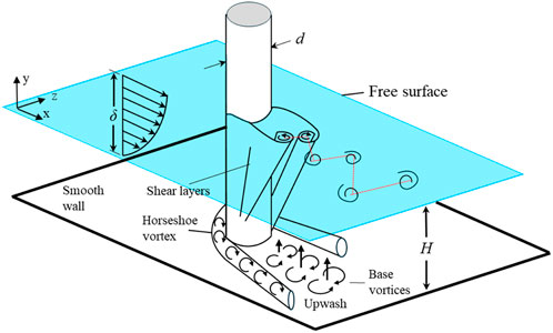
Figure 1. Flow features of flow past bed-mounted emergent circular cylinder [Adapted from Wang et al. (2006)]. Nomenclature:
1.2 Shallow flows
The wake dynamics of wall-mounted bluff bodies, such as circular cylinders, are complex and influenced by factors like the approaching flow boundary layer, bed friction, free surface interactions, and flow stability. In many situations, the flow can be deemed to be shallow, which occurs when the horizontal length scale of an eddy is much larger than the vertical scale (Balachandar et al., 2000). The development of vortices in such flows is affected by the wall and the free surface. Chen and Jirka (1995) categorized shallow near-wake structures into three types—von Kármán vortex street, unsteady wake bubble, and steady wake bubble—based on the stability parameter
1.3 Flow control mechanisms
Flow past a circular cylinder result in a periodic vortex shedding in the wake, leading to a drop in pressure and an increase in drag forces, as well as oscillating lift forces. These vortex-induced effects can cause structural vibrations and, in severe cases, lead to vortex-induced vibrations (VIVs) that can damage the structure (Ali et al., 2021; Ma et al., 2022; Janocha et al., 2022; Wu et al., 2022; Duranay et al., 2023; Xu and Ma, 2024; Sahu et al., 2024; Huera-Huarte, 2024). As a result, controlling vortex shedding is crucial in engineering applications to prevent such issues and improve the overall performance and durability of structures.
Among other engineering examples, flow past bed-mounted circular cylinders also resembles that around vegetation patches found in rivers and streams (Chatelain and Proust, 2021; Liu et al., 2021; Liu et al., 2022; Tariq et al., 2022; Tanaka, 2022; Kingora and Sadat, 2022; Barman and Kumar, 2022; Li et al., 2023). These interactions between fluid and vegetation create intricate flow patterns, promote turbulence, and have a significant impact on river ecosystems. Understanding how aquatic vegetation affects flow is vital for river restoration. Vegetation enhances ecology by aiding nutrient uptake, oxygen production, water purification, and filtering heavy metals like lead and mercury. The flow structure and turbulence downstream are crucial for these functions. Effective river system management thus requires a deep understanding of how the flow past cylinder modifies wake flow characteristics.
Additionally, understanding the flow characteristics and corresponding heat transfer behavior in the wake of bluff bodies is essential for developing and improving thermal management designs. Principal applications include electronic cooling systems and better thermal management systems. Flow past cylinders results in flow separation, and recirculation zones in the wake, which hinder effective heat transfer and lead to hotspots and uneven temperature distribution in cooling system designs (Terekhov, 2021; Abdollahzadeh Jamalabadi, 2021). Therefore, effective flow control mechanisms are required to address these flow and thermal challenges to disrupt stagnant flow regions, enhance turbulence, and promote better mixing in the wake.
Consequently, controlling the wake flow behind bluff bodies, especially circular cylinders, is an important aspect of engineering design. This has led to the development of various techniques, which are generally classified into active and passive flow control methods. The primary goal of both active and passive techniques is to reduce drag forces, control vortex shedding, and minimize the risk of VIV, thereby enhancing the stability and service life of structures (Zhao, 2023). These techniques help prevent damage and ensure the efficient functioning of engineering systems in various applications. Active control methods, such as suction flow, cylinder oscillation, and synthetic jets, use external energy sources to manipulate fluid flow and reduce vortex shedding (Chen et al., 2022). While these methods are effective, they can be costly and energy intensive. On the other hand, passive flow control techniques focus on altering the geometry of the cylinder to achieve similar results without requiring additional energy input (Ain et al., 2022). Additionally, passive methods are often favored for their lower cost, ease of implementation, and minimal maintenance needs. Examples include the use of splitter plates, control cylinders, protrusions, helical strakes, foam coverings, slots, holes, surface dimples, roughness elements, and grooves in different orientations (Mittal and Sharma, 2021; Eydi et al., 2022; Sun et al., 2022; Zhu et al., 2023; Zeng et al., 2023; Sahu et al., 2023; Wang and Li, 2023; Muñoz-Hervás et al., 2024; Murali and Petha Sethuraman, 2024; Sikdar et al., 2024; Zhu et al., 2024; Zhao et al., 2021; Rastan and Alam, 2021; Xiao and Jing, 2024; Kusano, 2024; Roy, 2023; Priyadarsan and Afzal, 2023; Zheng et al., 2023; Yu et al., 2024; Sharma et al., 2022; Sharma and Barman, 2023; Edegbe et al., 2024).
This paper aims to examine and compare various passive flow control mechanisms for managing wake flow behind bed-mounted plain cylinder (PC) in shallow flows, including the use of helical straked cylinder (HSC), meshed cylinder (MC), foam-covered cylinder (FC), single-slotted cylinder (SC), cross-slotted cylinder (CSC), and cylinder with holes (CWH). A simple schematic of such configurations is shown in Figure 2. The detailed literature review explores the principles, applications, and effects of each technique, including both experimental and numerical studies. While extensive literature exists for individual flow control techniques, comparative studies between different methods are notably absent. Moreover, particle image velocimetry (PIV) measurements were conducted to capture unsteady flow structures in the wake of these cylinders. The PIV measurements enabled a comparison of wake characteristics with and without passive flow control techniques for optimizing wake flow in engineering applications.
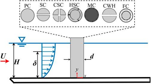
Figure 2. Schematic of flow past bed-mounted circular cylinders with cross-sections of the various cylinder designs with passive flow control strategies. Nomenclature:
The paper is arranged as follows: Section 2 discusses the current literature available on various flow control mechanisms, Section 3 shows the experimental setup used to investigate the effects on wake dynamics of circular cylinders, Section 4 provides the discussion of the results, and finally Section 5 concludes the research and provides future recommendations.
2 Review of passive flow control mechanisms
2.1 Helical straked and meshed cylinders (HSC and MC)
VIV is a significant concern in offshore engineering, particularly in the design of structures subjected to fluid flow, such as risers, pipes, and marine platforms (Duranay et al., 2023; Xu and Ma, 2024). VIV can lead to severe fatigue damage, reducing the operational lifespan of these structures and posing safety risks. As such, a wide array of techniques has been explored to mitigate VIV, with helical strakes and mesh coverings emerging as one of the most effective solutions (Korkischko and Meneghini, 2010). These devices, typically wrapped around cylindrical structures, disrupt the periodic vortex shedding that drives VIV, thereby reducing the amplitude of oscillations. In addition to VIV suppression, strakes have also been shown to affect heat transfer characteristics. The enhanced turbulence created by helical strakes can increase the convective heat transfer rate by improving the mixing of the boundary layer, leading to better thermal performance. A schematic of flow past a bed-mounted helical and meshed circular cylinders is shown in Figure 3, where
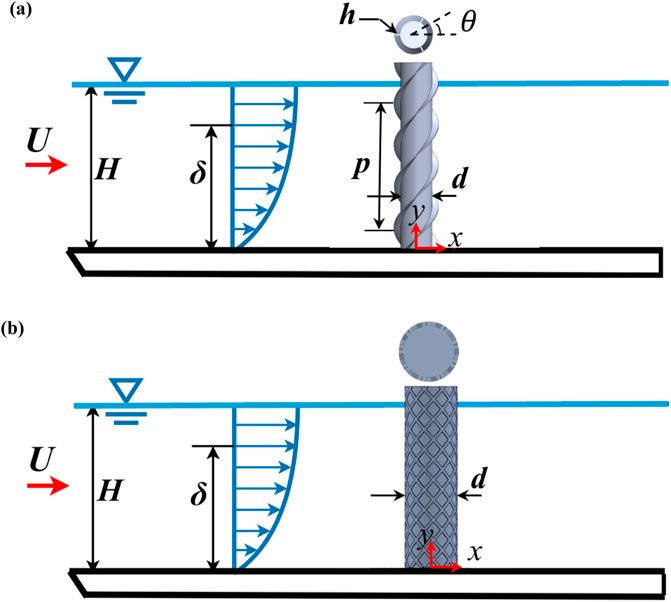
Figure 3. Schematic of flow past a bed-mounted (a) helical straked circular cylinder and (b) meshed circular cylinder. Nomenclature:
Numerous experimental studies have focused on the impact of helical strakes on flow past cylinders, exploring their effectiveness in reducing VIVs, listed in Table 1 (Korkischko and Meneghini, 2010; Hao et al., 2010; Zhou et al., 2010; Zhou et al., 2011; Huang, 2011; Korkischko and Meneghini, 2011; Huang and Sworn, 2013; Quen et al., 2014; Gao et al., 2014; Sui et al., 2016; Gao Y. et al., 2017; Senga and Larsen, 2017; Quen et al., 2018; Ren et al., 2019a; Ren et al., 2019b; Xu et al., 2020; Ren et al., 2020; Yadegari et al., 2023; Thakurta and Balachandar, 2025). Korkischko and Meneghini (Korkischko and Meneghini, 2010) tested different pitch and height combinations of helical strakes and found that smaller strake heights (

Table 1. Previous experimental and numerical studies on flow past helical straked and meshed circular cylinders. Nomenclature:
Similarly, Zhou et al. (2010), Zhou et al. (2011) conducted wind tunnel experiments on HSC, demonstrating up to 98% VIV reduction. The strakes eliminated lock-in behavior and weakened vortex shedding, causing phase mismatches along the cylinder’s height. This was further supported by velocity measurements, which showed significant variations in the dominant vortex frequency. Huang (2011) also focused on VIV suppression and drag reduction, showing a 64% reduction in VIV amplitude and a 25% drag reduction for fixed cylinders, underscoring the dual benefits of helical structures. Similarly, Korkischko and Meneghini (2011) used a two-camera stereoscopic PIV system to investigate the flow behind HSC. They found that strake pitch (
Quen et al. (2014) extended this research to flexible risers, showing that strakes with heights greater than the laminar boundary layer thickness were most effective in reducing VIV. They also found that
On the other hand, Senga and Larsen (2017) investigated the hydrodynamic coefficients of HSC through forced motion experiments—where controlled oscillations were applied to the test cylinder using a computer-controlled towing carriage equipped with a motion simulator and load cells for force measurement—and observed significant differences in drag and added mass coefficients compared to bare cylinders. These findings demonstrated how helical strakes disrupt vortex shedding and enhance flow stability. Similarly, Quen et al. (2018) examined two- and three-start helical strakes on a flexible cylinder, revealing that three-start strakes were more effective in reducing VIV amplitude. The best configuration involved a three-start strake with
In addition to these experimental findings, several computational studies have also explored the effects of helical strakes on VIV suppression, listed in Table 1 (Constantinides and Oakley, 2006; Carmo et al., 2012; Ranjith et al., 2016; Chen et al., 2019; Ishihara and Li, 2020). Constantinides and Oakley (Constantinides and Oakley, 2006) used a second-order finite element computational fluid dynamics (CFD) method to simulate VIV of bare and straked cylinders. They compared two turbulence models—Spalart-Allmaras Reynolds Averaged Navier Stokes (RANS) modelling and detached eddy simulation (DES)—and found that strakes effectively mitigated VIV by disrupting vortex shedding, with DES providing more accurate results than RANS. Carmo et al. (2012) utilized two- and three-dimensional (2D and 3D) simulations using spectral element method to study flow around cylinders with strakes. Their results showed that while 2D simulations were ineffective at suppressing vibrations, 3D simulations demonstrated that strakes reduced vortex shedding correlation along the span and altered vortex wake formation, thereby improving VIV suppression. Similarly, Ranjith et al. (2016) numerically examined the effects of three-strand helical strakes on VIV suppression for a rigid circular cylinder at
Expanding on this work, Chen et al. (2019) conducted 3D CFD simulations to investigate helical strakes’ impact on VIV suppression in flexible risers. They found that strakes disrupted vortex structures and reduced vortex shedding frequency, achieving a 97% reduction in transverse vibration at a reduced velocity of 7. In a similar manner, Ishihara and Li (2020) studied VIV suppression in HSC using a large eddy simulation (LES) model. Their study showed that helical wires reduced VIV amplitude by nearly 80%, primarily by enhancing 3D disturbances in the wake, thus reducing fluctuating lift forces and improving aerodynamic damping. While the effectiveness of helical strakes in mitigating VIV has been consistently demonstrated across a wide range of experimental and numerical studies, the effect on heat transfer rates due to the vortical structures responsible for enhanced turbulence still needs to be explored.
2.2 Single-slotted cylinders (SC)
Another method to modify and control the flow separation and wake dynamics is the use of slots. The flow from the slot acts as a jet in the wake region, disrupting stagnant flow regions and increasing turbulence. This helps in controlling wake to reduce vortex formations and improving heat transfer in various engineering designs. A schematic of flow past a bed-mounted slotted circular cylinder is shown in Figure 4a, where
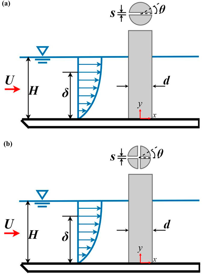
Figure 4. Schematic of flow past a wall-mounted (a) single-slotted cylinder and (b) cross-slotted cylinder. Nomenclature
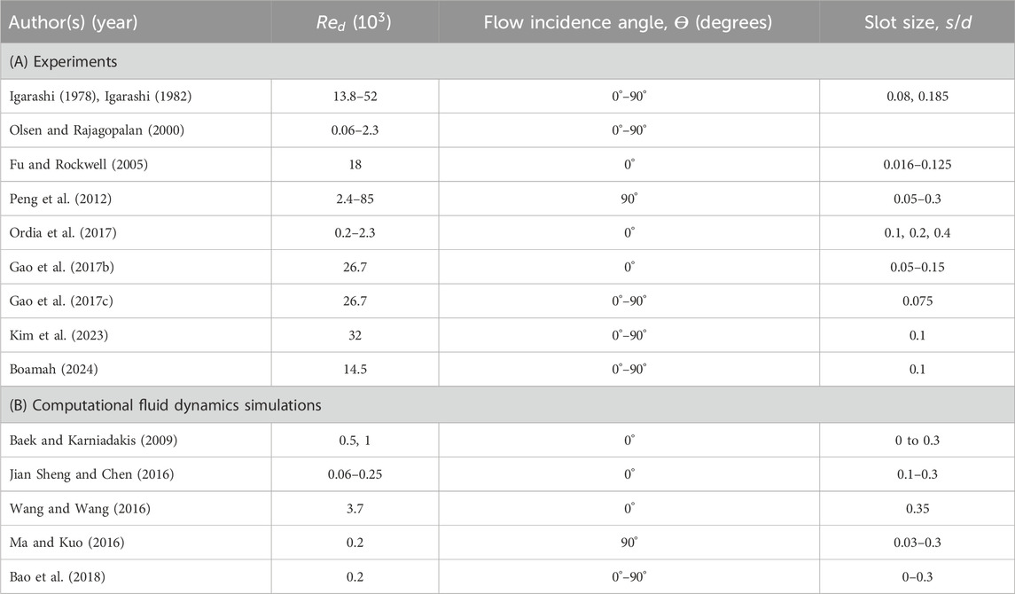
Table 2. Previous experimental and numerical studies on flow past single-slotted circular cylinders.
Building on this foundation, further investigations by Olsen and Rajagopalan (2000) explored vortex shedding in SC and concave rear notches. They noted distinct differences in the Strouhal number and drag coefficient compared to plain cylinders. For a cylinder with a slot normal to the flow, the drag coefficient reached 1.41, higher than the baseline case. Stable vortex shedding patterns were observed at specific Reynolds numbers, providing insights into modifying wake structures. In another study, Fu and Rockwell (2005) examined shallow flow past a cylinder with base bleed through a narrow slot using PIV measurements, demonstrating its ability to delay vortex formation significantly. The delayed vortex formation was attributed to the interaction between the base bleed and near-wake flow structures.
Peng et al. (2012) expanded this understanding by focusing on vortex shedding from SC in both wind tunnel and water channel experiments. They found an optimal range of
Gao et al. (2017b), Gao et al. (2017c) extended the exploration by studying flow characteristics around SC at various
Similarly, researchers have conducted numerous numerical studies to highlight the effectiveness of slots as passive flow control mechanisms, listed in Table 2 (Baek and Karniadakis, 2009; Jian Sheng and Chen, 2016; Wang and Wang, 2016; Ma and Kuo, 2016; Bao et al., 2018). By altering wake structures, delaying separation, and modifying vortex dynamics, slots enable enhanced aerodynamic performance and flow management across a wide range of applications. For instance, Baek and Karniadakis (2009) conducted simulations using spectral element method to investigate the hydrodynamic effect of SC to minimize VIV without energy consumption. The slot, positioned parallel to the incoming flow, effectively suppressed VIV by weakening or detuning vortex shedding. At
Building on this, Jian Sheng and Chen (2016) explored the impact of a slot positioned along the diameter of a circular cylinder for drag reduction and vortex suppression. The study demonstrated that drag reduction occurred by diverting fluid from the front stagnation region to the low-pressure zone behind the cylinder. In the range of
Additionally, Ma and Kuo (2016) conducted 2D flow simulations around a circular cylinder with a normal slot at
2.3 Cross-slotted cylinders (CSC)
Building on the work done on single slots, researchers have explored the use of multiple slotted cylinders in modifying the flow characteristics, suppress vortex shedding, reducing drag, and enhancing heat transfer. A schematic of flow past a bed-mounted slotted circular cylinder is shown in Figure 4b, where
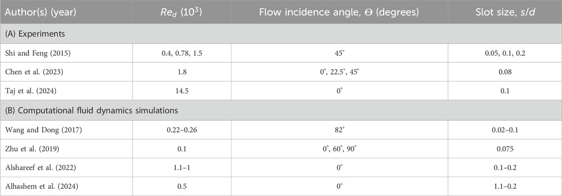
Table 3. Previous experimental and numerical studies on flow past multiple slotted circular cylinders.
Building on this, Chen et al. (2023) examined the wake dynamics of a circular cylinder with two perpendicular slots at
In a numerical context, Wang and Dong (2017) studied the flow and heat transfer characteristics of a multiple slotted cylinder. Their results showed that increasing
Furthermore, Alshareef et al. (2022) examined cylinders with orthogonal and parallel slots under transverse flow for
2.4 Foam-covered cylinders (FC)
The addition of a foam covering alters flow and turbulence patterns by interrupting large-scale structures and minimizing flow-induced oscillations, which can otherwise compromise structural integrity (Bruneau and Mortazavi, 2008). Porous media provide a passive method for wake flow control while protecting the main body by introducing an alternate flow zone that separates the structure from oscillations. This intermediate zone breaks up large-scale vortices, reduces vortex shedding frequency, and minimizes VIV. Additionally, FC reduce aerodynamic drag, offer shelter for aquatic habitats, and find applications in filters, mixers, heat exchangers, and environmental studies like aquatic vegetation flows and fish passages near hydraulic structures (Arbak and Dukhan, 2020; Li et al., 2021; Boules et al., 2021; Freitas et al., 2022; Hu et al., 2023).
A schematic of flow past a bed-mounted foam-covered circular cylinder is shown in Figure 5. FC comprises an inner solid cylinder wrapped in highly porous foam. Fluid flows through the porous region, emerging from the sides or rear end while vertical bleeding is restricted by the enclosing plates. This porous flow creates an intermediate velocity zone, shielding the wake of the inner cylinder and delaying shear layer roll-ups, which extend the recirculation region. The foam structure further stretches this region, carrying fluid downstream and reattaching to the bottom wall over a longer distance.
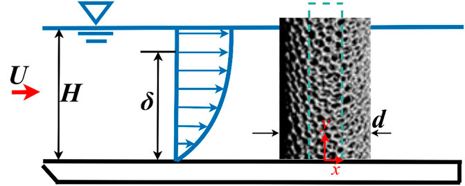
Figure 5. Schematic of flow past a bed-mounted foam-covered circular cylinder.
The addition of porous or foam materials to the surface of cylinders has been investigated experimentally in the past to modify flow characteristics (Sueki et al., 2010; Zong and Nepf, 2012; Ashtiani Abdi et al., 2014; Yuan et al., 2016; Klausmann and Ruck, 2017; Ashtiani Abdi et al., 2017; Xia et al., 2018; Du et al., 2022; Xu et al., 2023; Das et al., 2023). For example, Sueki et al. (2010) explored the application of porous materials using PIV to reduce aerodynamic sound from bluff bodies. Their experiments revealed a significant reduction in aerodynamic sound for porous-coated cylinders due to suppressed vortex shedding and stabilized shear layers. Surface pressure distribution and aerodynamic force fluctuations were altered, reducing unstable vortex motion, widened zero-velocity regions and reduced vortex shedding intensity. Similarly, Zong and Nepf (2012) studied the wake behind porous circular obstructions in a channel, mimicking vegetation. They found a steady wake region downstream, with length increasing with porosity (
Ashtiani Abdi et al. (2014) used hot-wire anemometery (HWA) technique to investigate heated FC across
Xia et al. (2018) used HWA, PIV, and smoke-wire visualization to study wake dynamics of porous-coated cylinders. Results indicated reduced Reynolds stresses, elongated vortex formation length, and widened wake regions. Proper orthogonal decomposition (POD) analysis revealed weakened asymmetrical vortex shedding for porous coatings, with symmetric modes gaining prominence. Moreover, Du et al. (2022) investigated drag reduction using porous materials of varying permeability on cylinder surfaces. Experiments showed a maximum drag reduction of 10.21% with optimized porous material placement. Flow visualization indicated expanded vortex regions, reduced shedding frequency, and dissipated vorticity. Furthermore, Xu et al. (2023) examined pressure drag and aerodynamic noise for cylinders with porous coatings. Experimental results showed that porous coatings suppress near-field pressure fluctuations and far-field noise. Key parameters, including pore density and coating thickness, were analyzed to optimize drag and noise reduction. Recently, Das et al. (2023) studied wake characteristics of FC using LES validated by PIV. Foam coverings interrupted large periodic structures, suppressed lateral oscillations, and shifted vortex regions downstream. Spectral analysis highlighted reduced dominant frequencies and modified recirculation regions.
Similarly, researchers have conducted numerous numerical studies to highlight the effect of foam coverings on fluid dynamics and heat transfer, listed in Table 4 (Das et al., 2023; Bhattacharyya et al., 2006; Bhattacharyya and Singh, 2011; Odabaee et al., 2011; Liu et al., 2014; Chang et al., 2017; Arcondoulis et al., 2019). For instance, Bhattacharyya et al. (2006) investigated flow past FC using numerical simulations. They examined
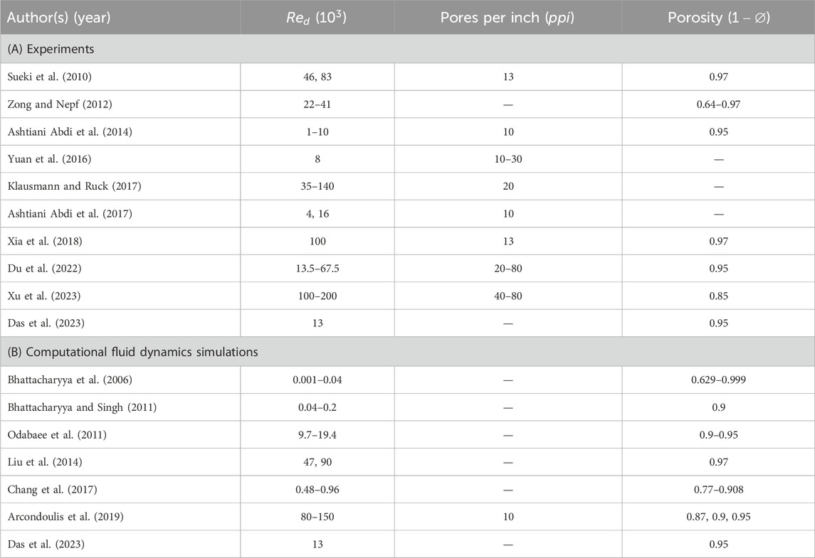
Table 4. Previous experimental and numerical studies on flow past foam-covered circular cylinders.
Furthermore, Odabaee et al. (2011) conducted numerical simulations on heat transfer augmentation from a metal FC in crossflow. They found an optimal porous layer thickness for maximizing heat transfer while minimizing pressure drop. Results showed higher heat transfer rates compared to finned-tube heat exchangers, emphasizing the effectiveness of metal foam coatings. Likewise, Liu et al. (2014) analyzed flow past FC using unsteady RANS simulations. They demonstrated that porous coatings mitigated aerodynamic force fluctuations, suppressed vortex shedding, and reduced mean drag. The sensitivity of aerodynamic forces to coating thickness was highlighted, showing its importance in flow-induced noise reduction and aerodynamic optimization. Building on this, Chang et al. (2017) examined the effects of solid volume fraction, relative cylinder diameter, turbulence structures, and sediment erosion using DES. Their findings provided insights into wake dynamics and sediment transport in vegetative flows. Lastly, Arcondoulis et al. (2019) designed structured porous materials for passive flow and noise control around cylinders. The results demonstrated the effectiveness of 3D-printed porous coatings in reducing vortex shedding tones and aerodynamic noise. The structured porous design showed potential for further optimization and tailored flow control applications. While foam-covered cylinders have shown promise in attenuating vortex shedding and suppressing wake instabilities, comprehensive studies investigating the unsteady wake dynamics—particularly at higher
2.5 Cylinders with holes (CWH)
Although introducing slots along the entire span of the cylinder has proven effective in altering flow behavior, increasing the slot width to enhance performance often compromises the structural integrity of the model. Similarly, a continuous slot along the cylinder weakens the body’s overall stability. To address these limitations, an array of holes drilled through the cylinder offer an alternative. This approach retains the advantages of passive flow control while maintaining the structural strength of the model, making it a practical solution for engineering applications. A schematic of flow past a bed-mounted CWH is shown in Figure 6, where
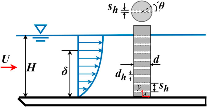
Figure 6. Schematic of flow past a bed-mounted circular cylinder with holes. Nomenclature:
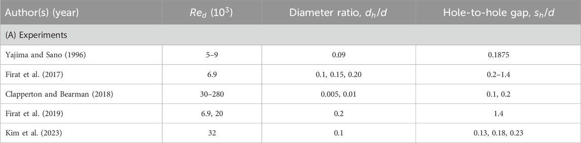
Table 5. Previous experimental studies on circular cylinders with holes.
Clapperton and Bearman (2018) examined passive jets generated through spanwise holes at
The detailed literature review explored the principles, applications, and effects of various passive flow control mechanisms for managing wake flow behind bed-mounted PCs, incorporating both experimental and numerical studies. While extensive research exists on individual flow control techniques, comparative studies between different methods are notably lacking. Additionally, the literature reveals variations in approach flow conditions across studies. Therefore, there is a need to evaluate and compare the wake flow characteristics of these passive mechanisms under identical or near-identical inflow conditions.
3 New experiments
PIV experiments were conducted in a recirculating water flume at the University of Windsor (shown in Figure 7). (Thakurta and Balachandar, 2025; Das et al., 2023) The flume has a rectangular cross-section with 16 m length, 1.2 m width, and 0.8 m height. The side and bottom walls of the flume are made from transparent Plexiglas, allowing optical access to the flow. To minimize inflow disturbances, upstream settling chambers consisting of three honeycomb flow straighteners are placed at the entrance of the channel. The flow straighteners, 1 m apart, are located well ahead of the measurement section. To regulate the level of water in the flume, an acrylic smooth plate, transparent and 0.5 inches thick, is positioned parallel to the bed of the flume (shown in Figure 8). The smooth plate measures
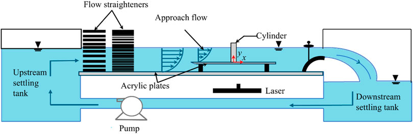
Figure 7. Experimental setup [Adapted from Das et al. (2023)].
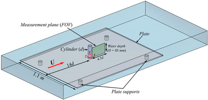
Figure 8. Measurement plane used in the current experimental setup.
Various circular cylinders with and without passive modifications, including PC, SC, CSC, CWH, HSC, FC, and MC, were investigated at emergent condition (shown in Figure 2). Table 6 shows the parameters used for various cylinder types in current experimental studies. The flow velocity measurements were carried out using a planar PIV system. To capture the variation of velocity along the flow depth, the field-of-view (FOV) in the vertical midplane (x-y plane) was chosen (shown in Figure 8). The system included dual pulse Nd:YAG lasers (Litron Nano PIV Laser) with a wavelength of 532 nm and 120 mJ/pulse energy. Cylindrical lenses with focal lengths of 15 mm and 25 mm were used to generate a laser sheet of around 2 mm. PIV images from two PowerViewPlus 8 MP CCD cameras with a resolution
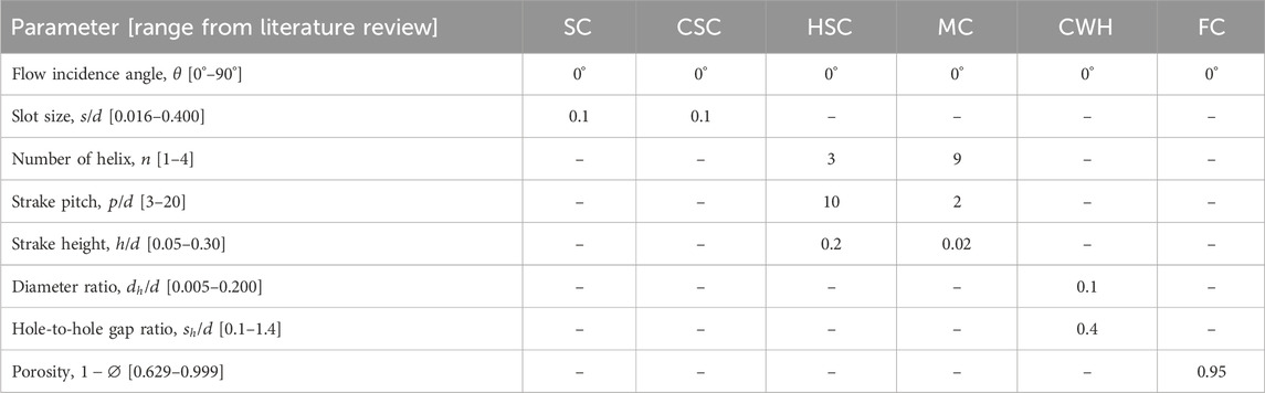
Table 6. Parameters used for various cylinder types in current experimental studies. Nomenclature:
PIV images were processed using open-source PIVlab software (Thielicke and Stamhuis, 2014). Initial background subtraction was followed by the contrast-limited adaptive histogram equalization (CLAHE) technique (Pizer et al., 1987). The image pairs were correlated using the Fast Fourier Transform window deformation algorithm. The image analysis occurred in two stages: initially, using
4 Results and discussion
Figure 9 shows the contour plots of the mean streamwise velocity (
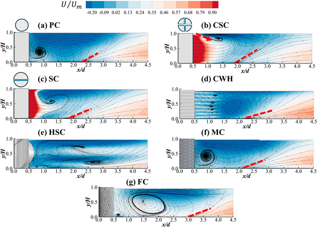
Figure 9. Comparison of mean normalized streamwise velocity contours superimposed with velocity streamlines in the vertical mid plane. Nomenclature:
The velocity contour for the cross-slotted cylinder (CSC), shown in Figure 9b, exhibits a markedly different trend compared to PC in Figure 9a. A region of high magnitude of mean streamwise velocity (
A similar trend is observed for the single-slotted cylinder (SC) in Figure 9c. A region of high magnitude of mean streamwise velocity (
For the cylinder with holes (CWH) in Figure 9d, six distinct spiraling flow regions are observed, resulting from the interaction of the positive velocity issuing from the holes with the downward velocity in the wake region. It should be noted that the jets near the free surface and the bed do not have distinct spiraling flows. The streamwise velocity contour for the CWH indicates that the flow through the holes is less intense than the jet flow from the slots in the CSC and SC cases (Figures 9b,c). Furthermore, the flow bifurcation point shifts downstream to
In the case of the helical straked cylinder (HSC) in Figure 9e, the wake flow is guided by the helical strakes, confined by the bed and the free surface, resulting in three distinct focal points indicated by spiraling stream traces centered at
For the foam-covered cylinder (FC) in Figure 9g, two distinct recirculation regions are observed: a primary recirculation region located at
Figure 10 shows the contour of mean vertical velocity (
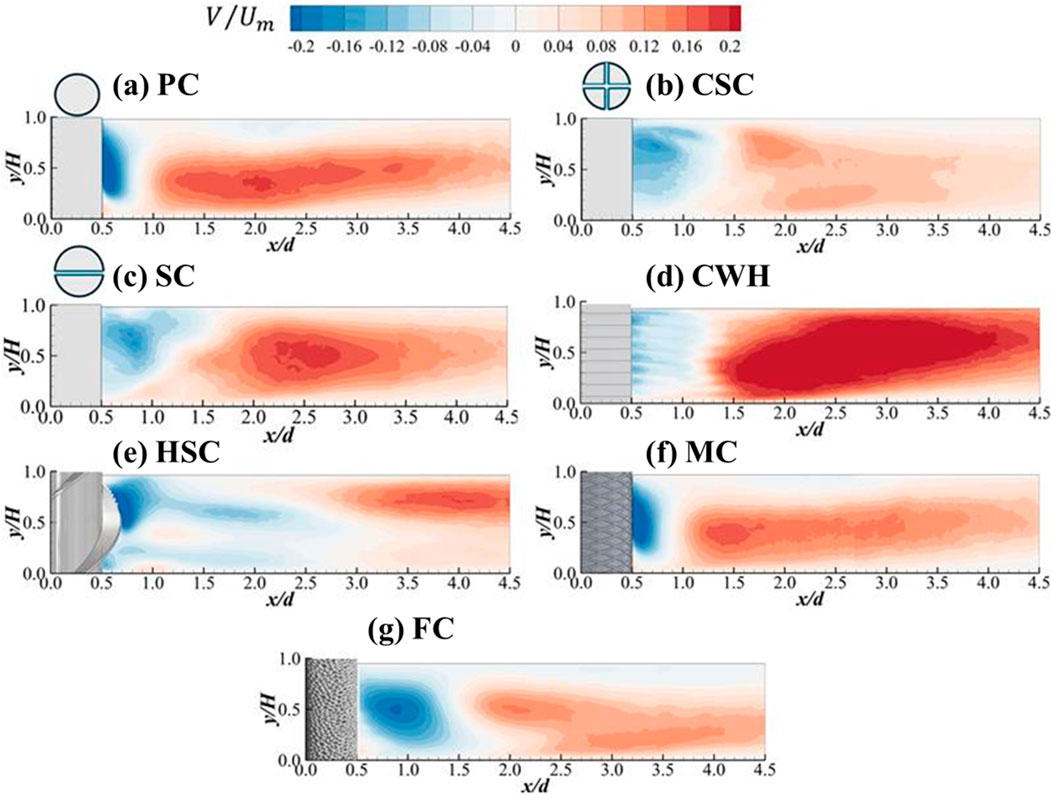
Figure 10. Comparison of mean normalized vertical velocity contours superimposed with velocity streamlines in the vertical mid plane. (a) PC, (b) CSC, (c) SC, (d) CWH, (e) HSC, (f) MC, (g) FC.
For the CSC case, Figure 10b, incorporating two perpendicular slots significantly alters the vertical velocity field in the wake. Primarily, the region of negative velocity behind the cylinder is significantly larger than PC, however, the magnitude is comparatively lower due to the jet issuing from the slot. The strong streamwise velocity from the slot weakens the roll-up of the streamlines behind the cylinder, as observed in the case of PC, thus weakening the downward flow along the cylinder. Furthermore, the magnitude of
In case of SC, Figure 10c, with one parallel slot, the wake’s vertical velocity field is altered, though less dramatically than in the CSC case. The magnitude of the upward flow after
Figure 10d shows the mean vertical velocity contours for CWH. Similar to the slotted cases, the holes allow fluid to bleed through the back, weakening vortex development. The
In Figure 10e, unlike the slotted configurations, the HSC uses external strakes to modify the flow field. These helical strakes generate secondary, spiraling flow structures that disrupt coherent vortex shedding and induce helical motion in the wake. The region of negative
For the case of MS, Figure 10f, the flow pattern is similar to that of PC case, which further supports the minimal impact of the mesh on the wake flow dynamics as highlighted previously. In case of FC, Figure 10g, the negative velocity region (
While the velocity contour plots provided an overall view of the flow field features behind different cylinder configurations, analyzing velocity profiles at various streamwise locations is essential to gain more insights into these effects. These profiles offer a more detailed perspective on the distribution and variation of flow velocity in the wake. Figures 11a,b present the distribution of the mean streamwise velocity (
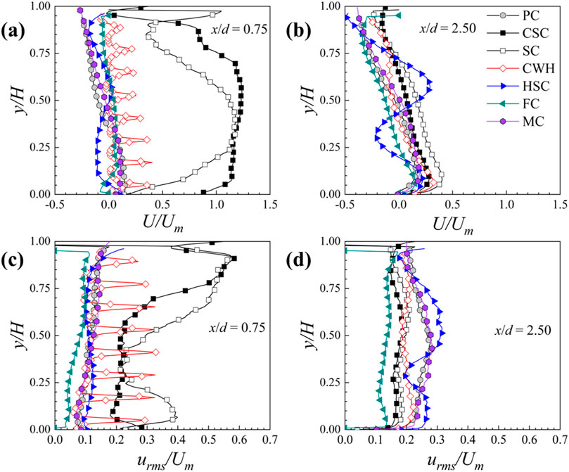
Figure 11. Comparison of mean normalized streamwise velocity and normalized turbulent kinetic energy profiles at different streamwise locations in the vertical mid plane. (a) U/Um at x/d = 0.75, (b) U/Um at x/d = 2.50, (c) urms/Um at x/d = 0.75, (d) urms/Um at x/d = 2.50.
The velocity profiles for the CWH show a markedly different trend, with distinct peaks aligned with the high-velocity regions issuing from the holes, as observed in Figure 9d. For the foam cylinder (FC), at
Further downstream at
Figures 11c,d illustrate the root mean squared streamwise velocity (
The
Figure 12 shows the contours of the root mean squared streamwise velocity (
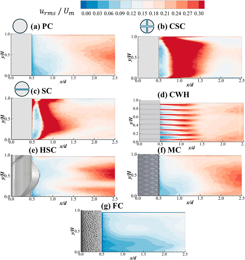
Figure 12. Comparison of mean normalized root mean squared streamwise velocity contours in the vertical mid plane. (a) PC, (b) CSC, (c) SC, (d) CWH, (e) HSC, (f) MC, (g) FC.
In the case of the CWH, shown in Figure 12d, high levels of
In the case of FC, the contours of
To better understand the flow field dynamics for each cylinder configuration, instantaneous contours of the normalized streamwise velocity (
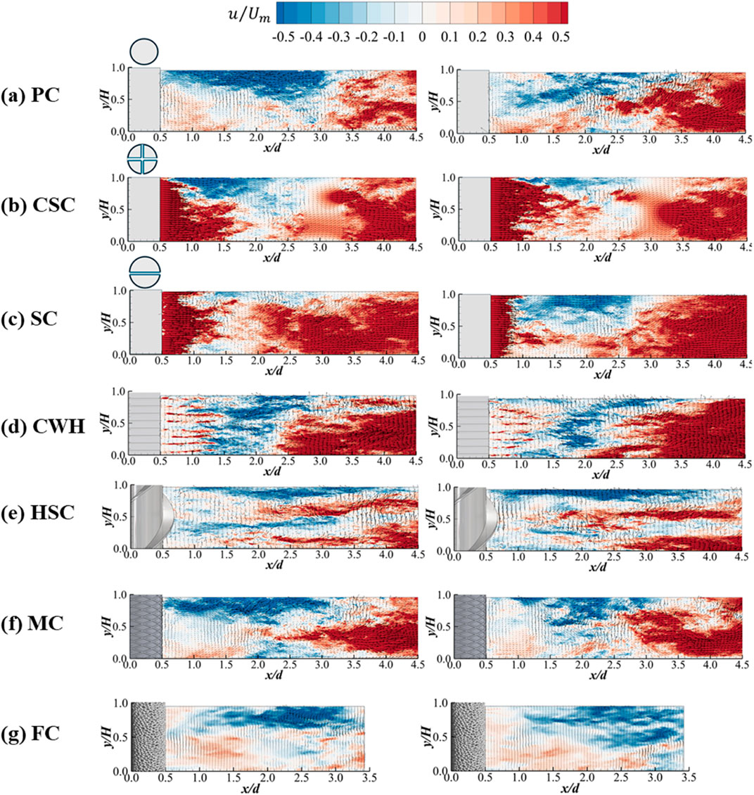
Figure 13. Comparison of instantaneous flow field at two instances in the vertical mid plane. (a) PC, (b) CSC, (c) SC, (d) CWH, (e) HSC, (f) MC, (g) FC.
The PC case, depicted in Figure 13a, shows that its wake is predominantly characterized by positive streamwise velocity across the cylinder height, except near the free surface (approximately
The CSC produces a strong jet of streamwise flow through its slots, resulting in a region of high positive velocity in the wake (Figure 13b). However, the jet’s distribution along the height varies with time. In the first snapshot, the jet is stronger in the lower half (
In the SC case (Figure 13c), the longitudinal slot produces a jet that also exhibits temporal variation. In the first snapshot, the jet extends farther downstream into the wake, whereas in the second instance it is shorter and more tightly confined near the cylinder. These differences imply a pulsating or “pumping” behavior of the jet, likely due to unsteady shear layer interactions at the slot opening.
For the CWH case, Figure 13d, the wake is marked by multiple high-velocity streaks (jets) emerging from the holes in the cylinder wall. In the first snapshot, these hole-induced jets are clearly visible, extending downstream to about
The HSC, Figure 13e, exhibits instantaneous flow structures that are not evident in the time-averaged results. These features—originating from unsteady shear layers shed at the tips of the strakes—act as localized disturbances in the wake, and their position and intensity vary between the two snapshots. Their irregular and intermittent appearance suggests that the strakes introduce wake instabilities which evolve and dissipate dynamically. Consequently, the HSC produces a more complex and unsteady wake field compared to the other configurations, even though these transient structures cancel out in the mean flow. Such unsteady flow behavior, characterized by frequent vortex interactions and enhanced mixing, can be beneficial for wake-induced heat transfer enhancement, particularly in applications where increased turbulence promotes improved convective performance. Whereas the MC case (shown in Figure 13f) shows instantaneous flow patterns very similar to those of the PC. No significant unique flow structures were observed in the MC case beyond what was described for the PC.
Lastly, the FC, Figure 13g, has a porous surface which allows some bleed-through of flow. This results in a region of positive streamwise velocity maintained close to the cylinder surface in the instantaneous snapshots, although its magnitude is lower than that observed for the CSC, SC, or CWH configurations. The region of negative streamwise velocity remains consistently confined near the free surface (
5 Conclusions and future recommendations
This study provides a comprehensive review of passive flow control mechanisms in flow past bed-mounted circular cylinders, including helical strakes, meshes, foam coverings, slots, and holes, highlighting their principles, applications, and effects. Existing experimental and numerical studies reveal a lack of comparative analyses and inconsistencies in the approach flow conditions of various flow control methods. To address this gap, particle image velocimetry measurements were conducted at a Reynolds number of
• For the plain cylinder, the wake flow is dominated by a large counterclockwise recirculation region induced by upwash from the bed. This results in negative velocities near the bed and a bifurcation point downstream.
• The cross-slotted cylinder and single-slotted cylinder introduce high-velocity jets in the wake region, significantly altering the flow structure. These jets shift the recirculation region upward and downstream, fix the flow separation points, and enhance turbulence intensity near the cylinder. Notably, the cross-slotted cylinder exhibits the highest velocity and turbulence in the near wake compared to the other cases, highlighting its potential for applications involving drag reduction and heat transfer enhancement. Moreover, it offers a weight reduction advantage compared to the helical straked cylinder.
• The cylinder with holes exhibits distinct spiraling flow regions and localized turbulence peaks due to interactions between flow through the holes and the wake region. However, the turbulence effect diminishes downstream.
• The helical straked cylinder demonstrates unique flow behavior, with the strakes guiding the wake flow and generating multiple focal points and channelized flow patterns. Unlike other configurations, the helical straked cylinder maintains pronounced meandering velocity profiles and high turbulence levels downstream, indicating a persistent influence of the strakes even in the far wake. However, the extra material added to the cylinder results in an increase in the overall weight of the system.
• The meshed cylinder exhibits minimal deviation from the flow characteristics of the plain cylinder, confirming the limited impact of the mesh on the wake flow.
• The foam-covered cylinder dampens flow fluctuations and reduces turbulence across the water depth, making it suitable for applications requiring flow stability and drag mitigation.
The current study provided an extensive review of individual passive flow control methods and addressed the gap in the lack of comparative studies evaluating the effectiveness of various techniques under similar flow conditions. To address the identified limitations of passive flow control mechanisms, the following recommendations are proposed for future research.
• Detailed numerical and experimental investigations are required to evaluate the influence of critical parameters such as flow incidence angles, Reynolds number, and slot spacing-to-diameter ratio for cross-slot configurations. This level of analysis is necessary to extend the understanding developed for single-slot cases to more complex configurations.
• While some experimental work has been conducted on cylinders with holes, a comprehensive numerical investigation of the flow field is lacking. Future research can be focused on high fidelity numerical simulations to gain further understanding into wake dynamics, turbulence modulation, and flow separation mechanisms associated with this configuration.
• Although helical strakes have been widely recognized for their effectiveness in mitigating vortex-induced vibrations, their influence on heat transfer rates remains unexplored. Future studies can be conducted on understanding the impact of the vortical structures induced by helical strakes on heat transfer rates.
• While this study presents a comprehensive experimental comparison of passive flow control strategies through detailed flow field analysis, future research should extend these findings by incorporating high-fidelity numerical simulations and directly investigating the effects on vortex-induced vibrations and convective heat transfer. Such complementary computational investigations would provide deeper insights into three-dimensional flow structures, pressure fields, and turbulence characteristics, thereby enhancing the overall understanding and applicability of these flow control techniques across diverse engineering scenarios.
Data availability statement
The raw data supporting the conclusions of this article will be made available by the authors, without undue reservation.
Author contributions
ZT: Data curation, Formal Analysis, Investigation, Methodology, Validation, Visualization, Writing – original draft, Writing – review and editing. SB: Formal Analysis, Investigation, Validation, Visualization, Writing – original draft. RB: Conceptualization, Funding acquisition, Investigation, Methodology, Project administration, Resources, Supervision, Validation, Visualization, Writing – review and editing.
Funding
The author(s) declare that financial support was received for the research and/or publication of this article. The authors acknowledge the support of the Natural Sciences and Engineering Research Council of Canada (NSERC) for funding this project under the Discovery Grant program.
Acknowledgments
The authors gratefully acknowledge the contributions of the Thermofluids Research Group at the University of Windsor. Shinneeb and Maria Gudisey provided the particle image velocimetry measurement data for cylinders with foam covering and holes, respectively. The results for single-slotted and helical straked cylinders were provided by Boamah and Thakurta, respectively. The authors also thank Roussinova for providing Figure 1.
Conflict of interest
The authors declare that the research was conducted in the absence of any commercial or financial relationships that could be construed as a potential conflict of interest.
The author(s) declared that they were an editorial board member of Frontiers, at the time of submission. This had no impact on the peer review process and the final decision.
Generative AI statement
The author(s) declare that no Generative AI was used in the creation of this manuscript.
Publisher’s note
All claims expressed in this article are solely those of the authors and do not necessarily represent those of their affiliated organizations, or those of the publisher, the editors and the reviewers. Any product that may be evaluated in this article, or claim that may be made by its manufacturer, is not guaranteed or endorsed by the publisher.
References
Abdollahzadeh Jamalabadi, M. Y. (2021). Active and passive control of a galloping cylinder with heat transfer. J. Therm. Analysis Calorim. 145, 1827–1835. doi:10.1007/s10973-020-10385-8
Ain, Q. U., Khan, Y., Mahmood, R., Alameer, A., Majeed, A. H., and Faraz, N. (2022). Passive control of hydrodynamic forces on a circular obstacle in a transient flow: FEM computations. Front. Phys. 10, 928087. doi:10.3389/fphy.2022.928087
Akilli, H., and Rockwell, D. (2002). Vortex formation from a cylinder in shallow water. Phys. Fluids 14 (9), 2957–2967. doi:10.1063/1.1483307
Alhashem, A., Alshareef, S., Alharbi, A. Y., and Alrahmani, M. A. (2024). Fluid dynamic and thermal performance of a V-shape slotted cylinder. Energies 17 (23), 6192. doi:10.3390/en17236192
Ali, U., Islam, M., Janajreh, I., Fatt, Y., and Alam, M. M. (2021). Flow-induced vibrations of single and multiple heated circular cylinders: a review. Energies 14 (24), 8496. doi:10.3390/en14248496
Alshareef, S., Harman, T., and Ameel, T. (2022). “Thermal fluid assessment of cylinders with multiple slots in aligned flow,” in 21st IEEE Intersociety Conference on thermal and Thermomechanical Phenomena in electronic systems (iTherm), 1–9.
Arbak, A., and Dukhan, N. (2020). Performance and heat transfer measurements in asymmetrically heated metal foam cooled by water. Therm. Sci. Eng. Prog. 20, 100688. doi:10.1016/j.tsep.2020.100688
Arcondoulis, E. J., Liu, Y., Li, Z., Yang, Y., and Wang, Y. (2019). Structured porous material design for passive flow and noise control of cylinders in uniform flow. Materials 12 (18), 2905. doi:10.3390/ma12182905
Ashtiani Abdi, I., Khashehchi, M., and Hooman, K. (2017). Investigation of coherence behind a single foamed tube. Fluid Mech. Res. Int. J. 1 (2), 45–54. doi:10.15406/fmrij.2017.01.00007
Ashtiani Abdi, I., Khashehchi, M., and Modirshanechi, M. (2014). “A comparative analysis on the velocity profile and vortex shedding of heated foamed cylinders,” in 19th Australasian fluid mechanics Conference (Australia: Australasian Fluid Mechanics Society).
Baek, H., and Karniadakis, G. E. (2009). Suppressing vortex-induced vibrations via passive means. J. Fluids Struct. 25 (5), 848–866. doi:10.1016/j.jfluidstructs.2009.02.006
Balachandar, R., Ramachandran, S., and Tachie, M. F. (2000). Characteristics of shallow turbulent near wakes at low Reynolds numbers. J. Fluids Eng. 122 (2), 302–308. doi:10.1115/1.483258
Balachandar, R., Tachie, M. F., and Chu, V. H. (1999). Concentration profiles in shallow turbulent wakes. Trans. ASME J. Fluids Eng. 121, 34–43. doi:10.1115/1.2822007
Bao, Z., Qin, G., He, W., and Wang, Y. (2018). Numerical investigation of flow around a slotted circular cylinder at low Reynolds number. J. Wind Eng. Ind. Aerodyn. 183, 273–282. doi:10.1016/j.jweia.2018.11.010
Barman, J., and Kumar, B. (2022). Turbulence in a compound channel with the combination of submerged and emergent vegetation. Phy. Fluid 34 (4). doi:10.1063/5.0086739
Bhattacharyya, S., Dhinakaran, S., and Khalili, A. (2006). Fluid motion around and through a porous cylinder. Chem. Eng. Sci. 61 (13), 4451–4461. doi:10.1016/j.ces.2006.02.012
Bhattacharyya, S., and Singh, A. K. (2011). Reduction in drag and vortex shedding frequency through porous sheath around a circular cylinder. Int. J. Numer. Methods Fluids 65 (6), 683–698. doi:10.1002/fld.2210
Boamah, J. (2024). Effect of incidence angle on the wake flow of a wall-mounted cylinder with a slot immersed in a shallow flow. Canada: University of Windsor. Master’s thesis.
Boules, D., Sharqawy, M. H., and Ahmed, W. H. (2021). Enhancement of heat transfer from a horizontal cylinder wrapped with whole and segmented layers of metal foam. Int. J. Heat. Mass Transf. 165, 120675. doi:10.1016/j.ijheatmasstransfer.2020.120675
Bruneau, C. H., and Mortazavi, I. (2008). Numerical modelling and passive flow control using porous media. Comput. Fluids 37, 488–498. doi:10.1016/j.compfluid.2007.07.001
Carmo, B. S., Gioria, R. S., Korkischko, I., Freire, C. M., and Meneghini, J. R. (2012). Two-and three-dimensional simulations of the flow around a cylinder fitted with strakes. Int. Conf. Offshore Mech. Arct. Eng. 44922, 781–790. doi:10.1115/omae2012-83603
Chang, W. Y., Constantinescu, G., and Tsai, W. F. (2017). On the flow and coherent structures generated by a circular array of rigid emerged cylinders placed in an open channel with flat and deformed bed. J. Fluid Mech. 831, 1–40. doi:10.1017/jfm.2017.558
Chatelain, M., and Proust, S. (2021). Open-channel flows through emergent rigid vegetation: effects of bed roughness and shallowness on the flow structure and surface waves. Phy. Fluid 33 (10). doi:10.1063/5.0063288
Chen, D., and Jirka, G. H. (1995). Experimental study of plane turbulent wakes in a shallow water layer. Fluid Dyn. Res. 16 (1), 11–41. doi:10.1016/0169-5983(95)00053-g
Chen, D. Y., Abbas, L. K., Wang, G. P., Rui, X. T., and Lu, W. J. (2019). Suppression of vortex-induced vibrations of a flexible riser by adding helical strakes. J. Hydr. 31 (3), 622–631. doi:10.1007/s42241-018-0078-6
Chen, G., Shahsavari, A., Hosseini, S., Kim, S., Chen, W. L., and Kim, K. C. (2023). Wake flow evolution behind a circular cylinder with two perpendicular slits at various angles of attack. J. Vis. 26 (6), 1233–1246. doi:10.1007/s12650-023-00934-2
Chen, W. L., Huang, Y., Chen, C., Yu, H., and Gao, D. (2022). Review of active control of circular cylinder flow. Ocean. Eng. 258, 111840. doi:10.1016/j.oceaneng.2022.111840
Clapperton, B. L., and Bearman, P. W. (2018). Control of circular cylinder flow using distributed passive jets. J. Fluid Mech. 848, 1157–1178. doi:10.1017/jfm.2018.399
Constantinides, Y., and Oakley, Jr O. H. (2006). Numerical prediction of bare and straked cylinder VIV. Int. Conf. offshore Mech. Arct. Eng. Hamburg 4, 745–753. doi:10.1115/omae2006-92334
Das, S., Abishek, S., Balachandar, R., and Barron, R. M. (2023). Wake characteristics of wall-mounted solid and foam-covered circular cylinders. Phys. Fluid 35 (11). doi:10.1063/5.0169165
Derakhshandeh, J. F., and Alam, M. M. (2019). A review of bluff body wakes. Ocean. Eng. 182, 475–488. doi:10.1016/j.oceaneng.2019.04.093
Du, H., Zhang, Q., Li, Q., Kong, W., and Yang, L. (2022). Drag reduction in cylindrical wake flow using porous material. Phys. Fluids 34 (4), 045102. doi:10.1063/5.0085990
Duranay, A., Demirhan, A. E., Dobrucali, E., and Kinaci, O. K. (2023). A review on vortex-induced vibrations in confined flows. Ocean. Eng. 285, 115309. doi:10.1016/j.oceaneng.2023.115309
Edegbe, M., Nasif, G., and Balachandar, R. (2024). Wake characteristics of near-wall submerged bluff bodies with varying streamwise length. Phy. Fluid 36 (11). doi:10.1063/5.0239290
Eydi, F., Mojra, A., and Abdi, R. (2022). Comparative analysis of the flow control over a circular cylinder with detached flexible and rigid splitter plates. Phy. Fluid 34 (11). doi:10.1063/5.0110398
Firat, E., Ozkan, G. M., and Akilli, H. (2017). PIV measurements in the near wakes of hollow cylinders with holes. Exp. Fluid 58, 39–19. doi:10.1007/s00348-017-2334-x
Firat, E., Ozkan, G. M., and Akilli, H. (2019). Flow past a hollow cylinder with two spanwise rows of holes. Exp. Fluid 60, 163–217. doi:10.1007/s00348-019-2814-2
Forouzi Feshalami, B., He, S., Scarano, F., Gan, L., and Morton, C. (2022). A review of experiments on stationary bluff body wakes. Phys. Fluids 34 (1). doi:10.1063/5.0077323
Freitas, R. B., Brandão, P. V., Alves, L. S. B., Celli, M., and Barletta, A. (2022). The effect of local thermal non-equilibrium on the onset of thermal instability for a metallic foam. Phys. Fluids 34 (3), 034105. doi:10.1063/5.0083045
Fu, H., and Rockwell, D. (2005). Shallow flow past a cylinder: control of the near wake. J. Fluid Mech. 539, 1–24. doi:10.1017/s0022112004002666
Gao, D. L., Chen, W. L., Li, H., and Hu, H. (2017b). Flow around a slotted circular cylinder at various angles of attack. Exp. Fluid 58, 132–215. doi:10.1007/s00348-017-2417-8
Gao, D. L., Chen, W. L., Li, H., and Hu, H. (2017c). Flow around a circular cylinder with slit. Exp. Therm. Fluid Sci. 82, 287–301. doi:10.1016/j.expthermflusci.2016.11.025
Gao, Y., Fu, S., Ma, L., and Chen, Y. (2014). Experimental investigation of the response performance of VIV on a flexible riser with helical strakes. Ships Offshore Struct. 11, 113–128. doi:10.1080/17445302.2014.962788
Gao, Y., Yang, J., Xiong, Y., Wang, M., and Lu, D. (2017a). VIV response of a long flexible riser fitted with different helical strake coverages in uniform and linearly sheared currents. Ships Offshore Struct 12 (4), 575–590. doi:10.1080/17445302.2016.1187832
Hao, Z., Zhou, T., Wang, X., and Tan, S. K. (2010). Experimental studies of vortex structures in the wake of a cylinder with helical strakes. Int. Conf. Offshore Mech. Arct. Eng. 49149, 473–477. doi:10.1115/omae2010-20181
Heidari, M., Balachandar, R., Roussinova, V., and Barron, R. M. (2017). Characteristics of flow past a slender, emergent cylinder in shallow open channels. Phys. Fluids 29 (6), 065111. doi:10.1063/1.4986563
Hu, J., Hu, K., Zhang, Y., Yang, X., and Wu, S. (2023). Experiment and simulation investigation of flow characters in metal foam. Numer. Heat. Transf. Part B 83 (1–2), 24–38. doi:10.1080/10407790.2022.2105124
Huang, S. (2011). VIV suppression of a two-degree-of-freedom circular cylinder and drag reduction of a fixed circular cylinder by the use of helical grooves. J. Fluids Struct. 27 (7), 1124–1133. doi:10.1016/j.jfluidstructs.2011.07.005
Huang, S., and Sworn, A. (2013). Hydrodynamic coefficients of two fixed circular cylinders fitted with helical strakes at various staggered and tandem arrangements. Appl. Ocean Res. 43, 21–26. doi:10.1016/j.apor.2013.06.001
Huera-Huarte, F. (2024). Vortex-induced vibration of flexible cylinders in crossflow. Annu. Rev. Fluid Mech. 57, 285–310. doi:10.1146/annurev-fluid-022724-014235
Igarashi, T. (1978). Flow characteristics around a circular cylinder with a slit: 1st report, flow control and flow patterns. Bull. JSME 21 (154), 656–664. doi:10.1299/jsme1958.21.656
Igarashi, T. (1982). Flow characteristics around a circular cylinder with a slit: 2nd report, effect of boundary layer suction. Bull. JSME 25 (207), 1389–1397. doi:10.1299/jsme1958.25.1389
Ishihara, T., and Li, T. (2020). Numerical study on suppression of vortex-induced vibration of circular cylinder by helical wires. J. Wind Eng. Ind. Aerodyn. 197, 104081. doi:10.1016/j.jweia.2019.104081
Janocha, M. J., Ong, M. C., and Yin, G. (2022). Large eddy simulations and modal decomposition analysis of flow past a cylinder subject to flow-induced vibration. Phy. Fluid 34 (4). doi:10.1063/5.0084966
Jian Sheng, W., and Chen, W. (2016). Features of flow past a circular cylinder with a slit. Sci. Iran. 23 (5), 2097–2112. doi:10.24200/sci.2016.3941
Kawamura, T., Mayer, S., Garapon, A., and Sorensen, L. (2002). Large eddy simulation of a flow pasta free surface piercing circular cylinder. J. Fluids Eng. 124 (1), 91–101. doi:10.1115/1.1431545
Kim, J., Chae, S., and Kim, J. (2023). Flow control over a circular cylinder using a slot and axially arranged holes. Ocean. Eng. 287, 115794. doi:10.1016/j.oceaneng.2023.115794
Kingora, K., and Sadat, H. (2022). Flow and scalar transfer characteristics for a circular colony of vegetation. Phy. Fluid 34 (8). doi:10.1063/5.0090272
Klausmann, K., and Ruck, B. (2017). Drag reduction of circular cylinders by porous coating on the leeward side. J. Fluid Mech. 813, 382–411. doi:10.1017/jfm.2016.757
Korkischko, I., and Meneghini, J. R. (2010). Experimental investigation of flow-induced vibration on isolated and tandem circular cylinders fitted with strakes. J. Fluids Struct. 26 (4), 611–625. doi:10.1016/j.jfluidstructs.2010.03.001
Korkischko, I., and Meneghini, J. R. (2011). Volumetric reconstruction of the mean flow around circular cylinders fitted with strakes. Exp. Fluids 51 (4), 1109–1122. doi:10.1007/s00348-011-1127-x
Kusano, K. (2024). Aeroacoustic simulation of bluff bodies with protrusions at moderate Reynolds number. Phy. Fluid 36 (2). doi:10.1063/5.0186743
Lekkala, M. R., Latheef, M., Jung, J. H., Coraddu, A., Zhu, H., Srinil, N., et al. (2022). Recent advances in understanding the flow over bluff bodies with different geometries at moderate Reynolds numbers. Ocean. Eng. 261, 111611. doi:10.1016/j.oceaneng.2022.111611
Li, D., Liu, M., Huai, W., Liu, G., Peng, Z., and Zhang, F. (2023). Conditional statistics of Reynolds stress in open channel flows with modeled canopies of homogeneous and heterogeneous density. Phy. Fluid 35 (3). doi:10.1063/5.0141128
Li, Y., Gong, L., Ding, B., Xu, M., and Joshi, Y. (2021). Thermal management of power electronics with liquid cooled metal foam heat sink. Int. J. Therm. Sci. 163, 106796. doi:10.1016/j.ijthermalsci.2020.106796
Liu, H., Wei, J., and Qu, Z. (2014). The interaction of porous material coating with the near wake of bluff body. J. Fluids Eng. 136 (2), 021302. doi:10.1115/1.4026071
Liu, M., Huai, W., Ji, B., and Han, P. (2021). Numerical study on the drag characteristics of rigid submerged vegetation patches. Phy. Fluid 33 (8). doi:10.1063/5.0060601
Liu, M., Yang, Z., Ji, B., Huai, W., and Tang, H. (2022). Flow dynamics in lateral vegetation cavities constructed by an array of emergent vegetation patches along the open-channel bank. Phy. Fluid 34 (3). doi:10.1063/5.0084287
Ma, H. L., and Kuo, C. H. (2016). Control of boundary layer flow and lock-on of wake behind a circular cylinder with a normal slit. Eur. J. Mech.-B/Fluids 59, 99–114. doi:10.1016/j.euromechflu.2016.05.001
Ma, L., Lin, K., Fan, D., Wang, J., and Triantafyllou, M. S. (2022). Flexible cylinder flow-induced vibration. Phy. Fluid 34 (1). doi:10.1063/5.0078418
Mittal, C., and Sharma, A. (2021). Flow-induced vibration of a flexible splitter-plate in the wake of a stationary cylinder. Phy. Fluid 33 (11). doi:10.1063/5.0071523
Muñoz-Hervás, J. C., Lorite-Díez, M., Ruiz-Rus, J., and Jiménez-González, J. I. (2024). Experimental study on the flow-induced vibrations of a circular cylinder with a rear flexibly hinged splitter plate. Phy. Fluid 36 (2). doi:10.1063/5.0184410
Murali, D., and Petha Sethuraman, V. R. (2024). Flow control using hot splitter plates in the wake of a circular cylinder: a hybrid strategy. Phy. Fluid 36 (1). doi:10.1063/5.0180008
Nguyen, Q. D., Lu, W., Chan, L., Ooi, A., and Lei, C, C. (2023). A state-of-the-art review of flows past confined circular cylinders. Phys. Fluids 35 (7). doi:10.1063/5.0157470
Odabaee, M., Hooman, K., and Gurgenci, H. (2011). Metal foam heat exchangers for heat transfer augmentation from a cylinder in crossflow. Transp. Porous Med. 86 (3), 911–923. doi:10.1007/s11242-010-9664-y
Olsen, J. F., and Rajagopalan, S. (2000). Vortex shedding behind modified circular cylinders. J. Wind Eng. Ind. Aerodyn. 86 (1), 55–63. doi:10.1016/s0167-6105(00)00003-9
Ordia, L., Venugopal, A., Agrawal, A., and Prabhu, S. V. (2017). Vortex shedding characteristics of a cylinder with a parallel slit placed in a circular pipe. J. Vis. 20, 263–275. doi:10.1007/s12650-016-0398-y
Peng, B. H., Miau, J. J., Bao, F., Weng, L. D., Chao, C. C., and Hsu, C. C. (2012). Performance of vortex shedding from a circular cylinder with a slit normal to the stream. Flow. Meas. Instrumen. 25, 54–62. doi:10.1016/j.flowmeasinst.2011.07.003
Pizer, S. M., Amburn, E. P., Austin, J. D., Cromartie, R., Geselowitz, A., Greer, T., et al. (1987). Adaptive histogram equalization and its variations. Comput. Graph. Image Process. 39 (3), 355–368. doi:10.1016/s0734-189x(87)80186-x
Priyadarsan, A., and Afzal, M. S. (2023). Numerical investigation of flow past a circular cylinder modified with a single groove at low Reynolds number. Phy. Fluid 35 (2). doi:10.1063/5.0137530
Quen, L. K., Abu, A., Kato, N., Muhamad, P., Sahekhaini, A., and Abdullah, H. (2014). Investigation on the effectiveness of helical strakes in suppressing VIV of flexible riser. Appl. Ocean Res. 44, 82–91. doi:10.1016/j.apor.2013.11.006
Quen, L. K., Abu, A., Kato, N., Muhamad, P., Tan, L. K., and Kang, H. S. (2018). Performance of two and three-start helical strakes in suppressing the vortex-induced vibration of a low mass ratio flexible cylinder. Ocean. Eng. 166, 253–261. doi:10.1016/j.oceaneng.2018.08.008
Ranjith, E. R., Sunil, A. S., and Pauly, L. (2016). Analysis of flow over a circular cylinder fitted with helical strakes. Procedia Technol. 24, 452–460. doi:10.1016/j.protcy.2016.05.062
Rastan, M. R., and Alam, M. M. (2021). Transition of wake flows past two circular or square cylinders in tandem. Phy. Fluid 33 (8). doi:10.1063/5.0062978
Ren, H., Xu, Y., Cheng, J., Cao, P., Zhang, M., Fu, S., et al. (2019b). Vortex-induced vibration of flexible pipe fitted with helical strakes in oscillatory flow. Ocean. Eng. 189, 106274. doi:10.1016/j.oceaneng.2019.106274
Ren, H., Xu, Y., Zhang, M., Fu, S., Meng, Y., and Huang, C. (2019a). Distribution of drag coefficients along a flexible pipe with helical strakes in uniform flow. Ocean. Eng. 184, 216–226. doi:10.1016/j.oceaneng.2019.05.038
Ren, H., Zhang, M., Cheng, J., Cao, P., Xu, Y., Fu, S., et al. (2020). Magnification of hydrodynamic coefficients on a flexible pipe fitted with helical strakes in oscillatory flows. Ocean. Eng. 210, 107543. doi:10.1016/j.oceaneng.2020.107543
Roy, D. K. S. (2023). Simulation of flow over a fixed and oscillating circular cylinder with different surface roughness patterns using a multi-block-multi-mesh framework immersed boundary method. Phy. Fluid 35 (11). doi:10.1063/5.0172658
Sahu, T. R., Chopra, G., and Mittal, S. (2024). Vortex-induced vibration of a circular cylinder in the supercritical regime. Phy. Fluid 36 (10). doi:10.1063/5.0229933
Sahu, T. R., Furquan, M., and Mittal, S. (2023). Symmetry-breaking response of a flexible splitter plate attached to a circular cylinder in uniform flow. Phy. Fluid 35 (12). doi:10.1063/5.0177041
Senga, H., and Larsen, C. M. (2017). Forced motion experiments using cylinders with helical strakes. J. Fluids Struct. 68, 279–294. doi:10.1016/j.jfluidstructs.2016.11.004
Sharma, B., and Barman, R. N. (2023). Unsteady flow past slotted circular cylinders in laminar regime: effect of slit shapes and Reynolds number. Phy. Fluid 35 (1). doi:10.1063/5.0130736
Sharma, B., Verma, G., and Barman, R. N. (2022). Steady flow of power-law fluids past a slotted circular cylinder at low Reynolds number. Phy. Fluid 34 (9). doi:10.1063/5.0102861
Shi, X. D., and Feng, L. H. (2015). Control of flow around a circular cylinder by bleed near the separation points. Exp. Fluid 56, 214–217. doi:10.1007/s00348-015-2083-7
Sikdar, P., Dash, S. M., and Lua, K. B. (2024). Vortex structure manipulation and drag reduction of tandem circular cylinders using a pitching splitter plate. Phy. Fluid 36 (12). doi:10.1063/5.0242588
Sueki, T., Takaishi, T., Ikeda, M., and Arai, N. (2010). Application of porous material to reduce aerodynamic sound from bluff bodies. Fluid Dyn. Res. 42 (1), 015004. doi:10.1088/0169-5983/42/1/015004
Suh, J., Yang, J., and Stern, F. (2011). The effect of air–water interface on the vortex shedding from avertical circular cylinder. J. Fluids Struct. 27, 1–22. doi:10.1016/j.jfluidstructs.2010.09.001
Sui, J., Wang, J., Liang, S., and Tian, Q. (2016). VIV suppression for a large mass-damping cylinder attached with helical strakes. J. Fluids Struct. 62, 125–146. doi:10.1016/j.jfluidstructs.2016.01.005
Sumner, D. (2013). Flow above the free end of a surface-mounted finite-height circular cylinder: a review. J. Fluids Struct. 43, 41–63. doi:10.1016/j.jfluidstructs.2013.08.007
Sun, Y., Wang, J., Fan, D., Zheng, H., and Hu, Z. (2022). The roles of rigid splitter plates in flow-induced vibration of a circular cylinder. Phy. Fluid 34 (11). doi:10.1063/5.0126867
Taj, Z., Bista, S., Balachandar, R., and Barron, R. (2024). “Wake dynamics of flow past wall-mounted cylinder with cross-slot,” in Proceedings of the Canadian Society for mechanical engineering International Congress, 31st Annual Conference of the computational fluid dynamics Society of Canada (Ontario, Canada).
Tanaka, N. (2022). Numerical investigation of 3D flow properties around finite emergent vegetation by using the two-phase volume of fluid (VOF) modeling technique. Fluids 7 (5), 175. doi:10.3390/fluids7050175
Tariq, H., Ghani, U., Anjum, N., and Pasha, G. A. (2022). 3D numerical modeling of flow characteristics in an open channel having in-line circular vegetation patches with varying density under submerged and emergent flow conditions. J. Hydro. Hydromech. 70 (1), 128–144. doi:10.2478/johh-2021-0034
Terekhov, V. I. (2021). Heat transfer in highly turbulent separated flows: a review. Energies 14 (4), 1005. doi:10.3390/en14041005
Thakurta, A., and Balachandar, R. (2025). On the wake dynamics of wall-mounted helical straked cylinders. Phys. Fluids 37 (1). doi:10.1063/5.0250201
Thielicke, W., and Stamhuis, E. (2014). PIVlab – towards user-friendly, affordable and accurate digital particle image velocimetry in MATLAB. J. Open Res. Softw. 2 (1), e30. doi:10.5334/jors.bl
Thompson, M. C., Leweke, T., and Hourigan, K. (2021). Bluff bodies and wake–wall interactions. Annu. Rev. Fluid Mech. 53 (1), 347–376. doi:10.1146/annurev-fluid-072220-123637
Wang, C., and Li, Y. (2023). Control of a circular cylinder flow using attached solid/perforated splitter plates at deflection angles. Phy. Fluid 35 (10). doi:10.1063/5.0165632
Wang, H. F., and Zhou, Y. (2009). The finite-length square cylinder near wake. J. Fluid Mech. 638, 453–490. doi:10.1017/s0022112009990693
Wang, H. F., Zhou, Y., Chan, C. K., and Lam, K. S. (2006). Effect of initial conditions on interaction between a boundary layer and a wall-mounted finite-length-cylinder wake. Phys. Fluids 18 (6), 065106. doi:10.1063/1.2212329
Wang, J., and Dong, Y. (2017). The numerical investigation of flow and heat transfer characteristics of flow past a slit-cylinder. Sci. China Tech. Sci. 60, 602–612. doi:10.1007/s11431-016-0375-8
Wang, J., and Wang, C. (2016). Heat transfer and flow characteristics of a rectangular channel with a small circular cylinder having slit-vent vortex generator. Int. J. Therm. Sci. 104, 158–171. doi:10.1016/j.ijthermalsci.2016.01.006
Westerweel, J., and Scarano, F. (2005). Universal outlier detection for PIV data. Exp. Fluids 39, 1096–1100. doi:10.1007/s00348-005-0016-6
Wu, Y., Cheng, Z., McConkey, R., Lien, F. S., and Yee, E. (2022). Modelling of flow-induced vibration of bluff bodies: a comprehensive survey and future prospects. Energies 15 (22), 8719. doi:10.3390/en15228719
Xia, C., Wei, Z., Yuan, H., Li, Q., and Yang, Z. (2018). POD analysis of the wake behind a circular cylinder coated with porous media. J. Vis. 21, 965–985. doi:10.1007/s12650-018-0511-5
Xiao, J., and Jing, D. (2024). Fluid flow and mixing in a channel with dual bluff bodies. Phy. Fluid 36 (1). doi:10.1063/5.0187211
Xu, C., Wang, C., Mao, Y., and Jiang, S. (2023). Experimental studies on pressure drag and aerodynamic noise of cylinder with porous coatings. Phys. Fluids 35 (6), 065123. doi:10.1063/5.0153779
Xu, W. H., and Ma, Y. X. (2024). A review on vibration control of multiple cylinders subjected to flow-induced vibrations. China Ocean. Eng. 38 (2), 183–197. doi:10.1007/s13344-024-0016-z
Xu, W. H., Yang, M., Ai, H. N., He, M., and Li, M. H. (2020). Application of helical strakes for suppressing the flow-induced vibration of two side-by-side long flexible cylinders. China Ocean. Eng. 34 (2), 172–184. doi:10.1007/s13344-020-0017-5
Yadegari, M., Khoshnevis, A. B., and Boloki, M. (2023). An experimental investigation of the effects of helical strakes on the characteristics of the wake around the circular cylinder. Iran. J. Sci. Technol. Trans. Mech. Eng. 47 (1), 67–80. doi:10.1007/s40997-022-00494-0
Yajima, Y., and Sano, O. (1996). A note on the drag reduction of a circular cylinder due to double rows of holes. Fluid Dyn. Res. 18 (4), 237–243. doi:10.1016/0169-5983(96)00015-9
Yu, H., Hu, H., Chen, W. L., Lu, Y., and Gao, D. (2024). Flow modulation mechanism in a cylinder with corrugated surfaces. Phy. Fluid 36 (1). doi:10.1063/5.0176679
Yuan, H., Xia, C., Chen, Y., and Yang, Z. (2016). “Flow around a finite circular cylinder coated with porous media,” in Proceedings of the 8th International Colloquium on bluff body aerodynamics and applications (Boston, Massachusetts).
Zeng, L., Zhao, F., Wang, H., Liu, Y., and Tang, H. (2023). Control of flow-induced vibration of a circular cylinder using a splitter plate. Phy. Fluid 35 (8). doi:10.1063/5.0160114
Zhao, M. (2023). A review of recent studies on the control of vortex-induced vibration of circular cylinders. Ocean. Eng. 285, 115389. doi:10.1016/j.oceaneng.2023.115389
Zhao, M., Mamoon, A. A., and Wu, H. (2021). Numerical study of the flow past two wall-mounted finite-length square cylinders in tandem arrangement. Phy. Fluid 33 (9). doi:10.1063/5.0058394
Zheng, C., Zhou, P., Zhong, S., and Zhang, X. (2023). On the cylinder noise and drag reductions in different Reynolds number ranges using surface pattern fabrics. Phy. Fluid 35 (3). doi:10.1063/5.0138074
Zhou, T., Razali, S. M., and Cheng, L. (2010). Investigation on suppression of vortex-induced vibration using helical strakes. Int. Conf. Offshore Mech. Arct. Eng. 49149, 891–900. doi:10.1115/omae2010-20984
Zhou, T., Razali, S. M., Hao, Z., and Cheng, L. (2011). On the study of vortex-induced vibration of a cylinder with helical strakes. J. Fluids Struct. 27 (7), 903–917. doi:10.1016/j.jfluidstructs.2011.04.014
Zhu, H., Chen, Q., Tang, T., Alam, M. M., Zhou, T., and Zhong, J. (2023). Flow-induced response and wake characteristics of a flexible splitter plate attached to a circular cylinder in laminar flow. Phy. Fluid 35 (12). doi:10.1063/5.0180616
Zhu, H., Chen, Q., Zhong, J., and Zhou, W. Z. T. (2024). Wake-induced response of a flexible splitter plate detachedly placed downstream of a circular cylinder. Phy. Fluid 36 (7). doi:10.1063/5.0217046
Zhu, H., Zhao, H., and Zhou, T. (2019). Direct numerical simulation of flow over a slotted cylinder at low Reynolds number. Appl. Ocean Res. 87, 9–25. doi:10.1016/j.apor.2019.01.019
Keywords: wake flow control, bed-mounted cylinders, passive flow control mechanisms, particle image velocimetry, cylinder with slots, helical strakes, foam coverings
Citation: Taj ZUD, Bista S and Balachandar R (2025) Passive flow control in the wake of bed-mounted cylinders: a review and new experimental insights. Front. Mech. Eng. 11:1595832. doi: 10.3389/fmech.2025.1595832
Received: 18 March 2025; Accepted: 13 May 2025;
Published: 21 May 2025.
Edited by:
Markus Holzner, Boku University vienne, AustriaReviewed by:
Isabella Schalko, Massachusetts Institute of Technology, United StatesMirko Musa, Swiss Federal Institute of Technology Lausanne, Switzerland
Copyright © 2025 Taj, Bista and Balachandar. This is an open-access article distributed under the terms of the Creative Commons Attribution License (CC BY). The use, distribution or reproduction in other forums is permitted, provided the original author(s) and the copyright owner(s) are credited and that the original publication in this journal is cited, in accordance with accepted academic practice. No use, distribution or reproduction is permitted which does not comply with these terms.
*Correspondence: Zia Ud Din Taj, dGFqekB1d2luZHNvci5jYQ==