 Ariq Naufal Rabbani1
 Cheng-Wei Chen
 Radon Dhelika
- 1Department of Mechanical Engineering, Faculty of Engineering, Universitas Indonesia, Depok, Indonesia
- 2Department of Electrical Engineering, National Taiwan University, Taipei, Taiwan
This study explores the development and performance evaluation of motorized hospital beds, which aim to alleviate the physical burden on healthcare workers and improve hospital efficiency. Traditional hospital beds, which require significant physical effort to maneuver, often lead to musculoskeletal injuries among healthcare workers. The proposed solution involves implementing mobile robot technology, specifically swerve drive systems, into conventional hospital beds to enhance their mobility. Two prototypes of motorized hospital beds were developed, each featuring different swerve drive configurations. Prototype 1 utilizes DC motors with chain-driven wheels for propulsion and a gear-based steering system. Prototype 2 employs a pulley and belt mechanism for propulsion and a servo motor for steering. Both prototypes underwent comprehensive motion testing, including straight-line and rotational motion tests, using ArUco markers for precise position and movement measurements. Results demonstrated that Prototype 2 significantly outperformed Prototype 1 in maintaining a straight trajectory, with an average deviation of 5.38 cm compared to 32.68 cm for Prototype 1. Factors influencing these results included initial positioning, wheel grip, and acceleration balance. The study concludes that the ArUco marker vision-based method is a reliable tool for measuring hospital bed movements. Prototype 2’s enhanced straight-line motion capability highlights its potential to reduce physical strain on healthcare workers. Further optimization and addressing mechanical and environmental factors can lead to the development of more efficient motorized hospital beds, ultimately improving hospital operations and patient care.
1 Introduction
Hospital beds primarily serve as a place for patients to lie down. Over time, the need for mobility in hospital beds has become increasingly important, especially for patients requiring special care, laboratory tests, and other procedures. This mobility is essential for efficiently moving patients within the hospital. Traditionally, hospital beds are designed with four caster wheels, allowing them to be easily maneuvered by nurses or specialized staff. There are two main types of hospital beds: those used in patient rooms and stretcher beds specifically for patient transport. In general, pushing hospital beds requires considerable physical effort, often involving at least two people, while moving larger hospital beds can require up to four people (Guo and Yu, 2016). This task can become particularly challenging when there is a shortage of healthcare personnel, which can occur due to various urgent responsibilities, especially during emergencies or extraordinary situations such as the COVID-19 pandemic (Nurhasan and Hariyanto, 2021). During the pandemic, healthcare resources were heavily allocated to treating COVID-19 patients, highlighting the limitations in healthcare staffing. Healthcare workers, equipped with multiple layers of personal protective equipment (PPE), including hazmat suits and masks, often experienced oxygen deficits, leading to fatigue and health risks (Haward et al., 2023).
Manually pushing hospital beds can cause injuries among healthcare workers, such as lower back pain, shoulder strain, and other musculoskeletal disorders. Musculoskeletal pain is prevalent among healthcare workers, with a significant proportion, about 45.8%, experiencing such issues (Gusmiah et al., 2020). These injuries are often due to the initial force required to move the hospital beds, especially during the initial push phase (Leban et al., 2022). While the concept of reducing the effort needed to use hospital beds has long been of interest, most advancements have focused on bed structure design and ergonomics to enhance patient comfort. There is limited research and product development addressing mobility aspects, which could significantly reduce the physical burden on healthcare workers by up to 21% (Kotowski et al., 2022). To address these concerns, Dhelika et al. (2021) proposed the development of a motorized hospital bed designed to improve safety and ease of use. These motorized hospital beds utilize swerve drive as the drivetrain due to its high maneuverability and efficiency in navigating tight spaces and various hospital environments. During the development process, two versions of the motorized hospital bed prototypes were developed, each with different configurations. However, ensuring the precise motion and control of such a motorized system in a hospital environment necessitates rigorous testing, particularly in evaluating its motion performance, path deviation, and path-following capabilities.
In the development of motorized hospital beds, it is essential to have a reliable and straightforward method for motion testing and performance evaluation. Precision in motion is critical in a hospital setting to avoid potential harm to patients and to ensure that the bed operates as intended (Morse et al., 2015). Typically, motion testing in motorized systems involves the use of encoders or accelerometers to measure speed, displacement, and orientation. However, these methods are sometimes limited in features and are prone to noise (DJB Electronic, 2024), (Rabbani et al., 2024).
We propose the use of ArUco fiducial markers as a tool to aid in evaluating the path-following performance of motorized hospital bed prototypes. ArUco markers are widely used in various applications for precise tracking and positioning, particularly in robotics. These markers serve two primary functions, i.e., localization, for identifying the relative position of a robot in real space, which is useful for mapping the surrounding area and pathfinding (Garrido-Jurado et al., 2014) and motion tracking for following the movement of the robot along a predefined path (Kyrki and Kragic, 2011).
While the distinction between localization and motion tracking is subtle, the main difference lies in their application. Localization typically involves no predefined path or location for the robot, requiring it to determine its coordinates based on markers scattered throughout the surrounding area. Previous studies by Lee et al. (2013) , Acuna et al. (2018), and Roos-Hoefgeest et al. (2021) provide examples of using ArUco markers for robot localization. Motion tracking, on the other hand, usually involves a predefined path that the robot attempts to follow. Markers are used to track the robot’s movement and compare it to the predetermined path to assess movement accuracy.
Previous studies, such as those by Hij et al. (2022) and Botta and Quaglia. (2020), have utilized ArUco markers for evaluating the path-following performance of mobile robots. However, it is crucial to note that the vast majority of these studies have focused exclusively on small-scale mobile robots. These compact robots, often weighing just a few kilograms and measuring less than a meter in any dimension, present significantly different challenges compared to larger mobile platforms. In contrast, our research aims to apply ArUco marker technology to a much larger mobile robot: a motorized hospital bed. These beds measure more than 2 m in length, presenting a host of unique challenges that have not been adequately addressed in previous ArUco marker studies. The increased size and weight of the hospital bed affect its maneuverability, turning radius, and overall dynamics, which in turn impact the movement performance in ways that cannot be directly extrapolated from small-scale robot studies.
The objective of this study is to evaluate the path deviation and performance of motorized hospital bed prototypes using ArUco fiducial markers, thereby bridging the gap between small-scale robotics research and practical applications in healthcare environments. In addition, we aim to highlight the advantages of the ArUco method compared to conventional manual measurement, particularly in terms of consistency and efficiency. Two prototypes with different swerve module designs were developed to provide a more robust testing platform and richer experimental insight. It is important to note, however, that the focus of this work is not a detailed comparison of the mechanical designs, but rather the validation of ArUco markers as a reliable tool for motion performance evaluation.
The evaluation of path deviation is critical in the development of these larger mobile robots, as it directly impacts the performance, reliability, and safety of the drivetrain design in a hospital setting. Traditional methods of testing this performance often involve manual measurements, which can be time-consuming and prone to error, especially when dealing with larger platforms like hospital beds. By employing fiducial markers, we aim to provide a simple, low-cost, and potentially adaptable solution for hospital environments, facilitating more accurate and efficient testing processes for these larger mobile robots. This research not only advances the field of mobile robotics but also has practical implications for improving patient transport and care in healthcare facilities.
2 Methods
2.1 Hospital bed description
This study focuses on the development of two types of motorized hospital beds by modifying conventional hospital bed designs. The prototypes feature dimensions of 200 cm × 60 cm × 85 cm, with a structure constructed from steel tubing. A swerve drive system was selected as the drivetrain for the motorized beds due to its exceptional maneuverability, allowing for omnidirectional movement (Oftadeh et al., 2013). This type of movement is crucial for hospital bed mobility, enabling the bed to be driven in any direction with ease. A swerve drive module comprises two main components: the propulsion part and the steering part, each of which can be controlled independently. This independent control provides the system with high movement flexibility. Both prototypes are equipped with two swerve drive modules installed diagonally, complemented by two caster wheels for balance. An Arduino Mega serves as the main controller for all electronic components. The prototypes differ in the specifications of their swerve drive modules and supporting components.
In Prototype 1 or P1 developed by Girindra et al. (2023), as shown in Figure 1, the propulsion system includes wheels driven by DC motors connected via chains, with motor speed monitored by a rotary encoder. The steering system uses a DC motor connected to a set of gears and bearings, allowing for left and right rotation, with the rotation angle measured by a Hall-effect non-contact potentiometer. The movement of modules in this first version of prototype is controlled by a set of pushbuttons for forward, backward and turning movement. This prototype employs only two swerve drive modules, in contrast to the more common practice of using four modules in similar designs. This decision was made to simplify the system’s construction process, reducing both the mechanical and control complexity involved. By streamlining the design in this way, not only is the overall build time reduced, but the material costs are significantly lowered as well. Additionally, the reduction in components means less maintenance and fewer potential points of failure, further contributing to the long-term reliability and affordability of the system.
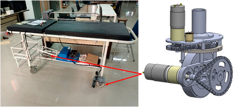
Figure 1. Prototype 1 or P1 of the swerve drive bed prototype by Girindra et al. (2023), with chain mechanism.
Prototype 2 or P2), as shown in Figure 2, employs a propulsion system where the DC motor is connected to the wheel using a pulley and belt mechanism. The motor speed is also monitored using an embedded rotary encoder. For steering, this version uses a servo motor connected to the wheel through a set of gears.
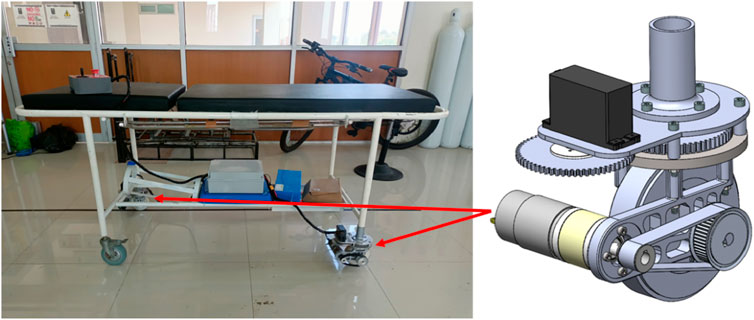
Figure 2. Prototype 2 or P2 of the swerve drive bed prototype, with pulley and belt mechanism.
2.2 ArUco marker
ArUco markers are a type of fiducial marker developed by the University of Cordoba (Romero-Ramirez et al., 2018), (Garrido-Jurado et al., 2016). Fiducial markers are physical objects used as reference points for image scanning, crucial for applications requiring precise and accurate position and orientation measurements, such as in medicine, robotics, and augmented reality. Besides ArUco markers, other commonly used fiducial markers include ARToolKit and AprilTags (Dos Santos Cesar et al., 2015). Compared to other types of markers, ArUco markers are renowned for their highly accurate and efficient detection and tracking capabilities (Garrido-Jurado et al., 2014). These markers are composed of binary patterns represented by black-and-white squares, which can serve various functions, such as pose estimation to determine the marker’s orientation relative to the camera in 3D space as shown in Figure 3 (Kalaitzakis et al., 2021). In addition to their utility in pose estimation, ArUco markers store information about the marker type and a unique ID, enabling each marker to be individually recognized by the detection algorithm. This unique identification, combined with the marker’s precise spatial information, makes ArUco markers particularly effective in applications requiring reliable tracking and localization.
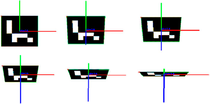
Figure 3. ArUco marker pose estimation result (Poroykov et al., 2020).
The detection process of an ArUco marker, as shown in Figure 4, begins with image acquisition by a camera that captures the marker’s image. Subsequently, the ArUco algorithm applies an adaptive thresholding algorithm to distinguish the marker from its background. This algorithm calculates the average pixel value surrounding each specific pixel to determine the threshold that separates light and dark areas in the image. Through this method, all contours in the image are identified, and non-square contours are filtered out.
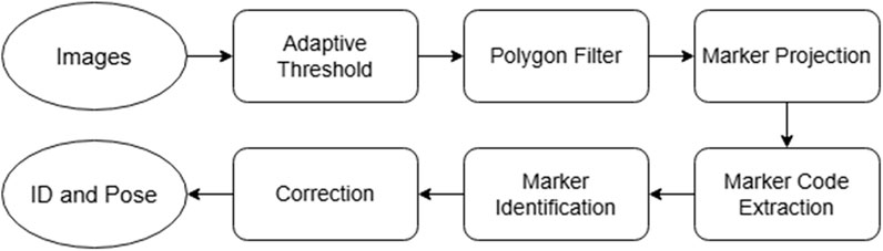
Figure 4. Marker identification flow (Xu et al., 2021).
Next, the algorithm performs a projection operation using the recognized contours to isolate areas that may contain markers. Once these areas are identified, a code extraction process is conducted to determine the detected ArUco marker pattern. This pattern is then compared with patterns stored in a database. The subsequent step involves error correction to ensure that the reading of pattern is accurate and to eliminate potential reading errors. Finally, a unique marker ID is generated, allowing each marker to be individually recognized. The final stage of this process involves estimating the marker’s pose relative to the camera. This pose estimation includes information on the marker’s position and orientation in three-dimensional space. It is performed using image processing algorithms that account for perspective and camera distortion to produce precise coordinates.
To perform position measurements using ArUco markers, a marker detection program was developed using the Python programming language and the OpenCV library, which includes features such as camera access, image processing, and the ArUco algorithm (Rosebrock, 2024). The markers used are of the 7 × 7 250 type, as shown in Figure 5a, printed on a paper with dimensions of 16 cm × 16 cm. Additionally, Figure 5b shows the photo of the marker in the experiment setting.
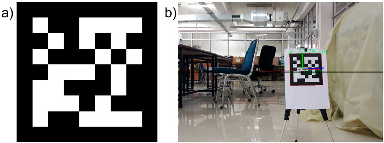
Figure 5. (a) ArUco marker 7 × 7 250, (b) Photo of the printed marker as identified by the program in one of the experiments.
Before testing the capability of the motorized hospital bed, an evaluation was conducted to determine whether the ArUco marker program could accurately measure distances. This was achieved by setting up an experiment where four markers were placed 20 cm apart from each other, arranged around a central origin point. Prior to taking measurements, the camera’s image frame was aligned so that its center matched the origin point. Measurements were then recorded at various distances from 1 to 5 m, in 1-m increments. The results for each marker were documented, and the measurement errors were calculated by comparing them to the actual 20 cm distance. The setting of this test is shown in Figure 6.
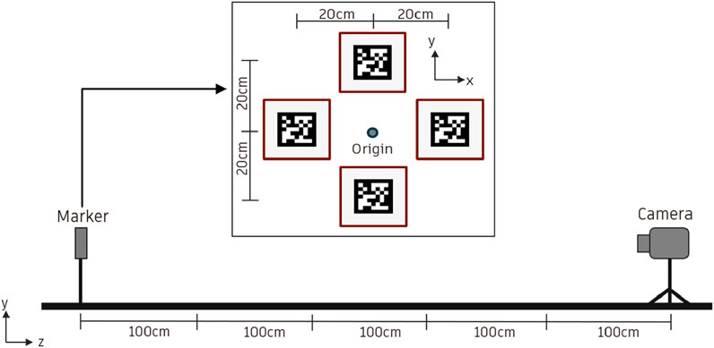
Figure 6. ArUco marker measurement testing.
2.3 Experimental setup
In conducting motion testing for hospital beds, two distinct procedures were employed, namely, straight motion and rotational motion testings. For straight motion testing, as shown in Figure 7a, beds were positioned 5 m from a marker, with a camera placed underneath the bed to ensure zero deviation for x-axis readings relative to the marker. The bed was then moved forward to within 1 m of the marker, and deviations from the intended path were recorded as deviation data. This procedure was repeated 10 times for each of the two bed prototypes.
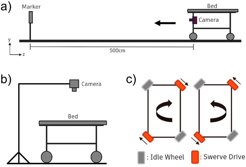
Figure 7. Schematics of experimental setups, (a) Straight motion experiment setup, (b) Rotational motion experimental setup, and (c) Diagrams of rotational directions of the swerve drive modules during bed’s clockwise and counterclockwise motions.
Figure 7b shows the schematic for the rotational motion testing, in which the bed was initially placed on a square marker on the floor. An ArUco marker was centrally affixed to the bed, with a camera positioned 100 cm above it and oriented towards the marker. The bed was then rotated 360° both clockwise and counterclockwise, and deviations in position were recorded as deviation values.
For the rotational movement, all swerve drive modules were turned at a 27° angle. Figure 7c illustrates the rotation direction of each swerve wheel. When the front swerve wheel moved backward and the rear swerve wheel moved forward, it resulted in a clockwise rotation. Reversing this movement produced a counterclockwise rotation. This rotational testing was conducted 10 times, alternating between clockwise and counterclockwise rotations to ensure a comprehensive evaluation.
3 Results and discussion
The experiment is conducted in a controlled environment where each test is performed. Below is the result of the experiment of movement for motorized hospital bed based on methodology stated previously.
3.1 Marker measurement result
The marker measurement process was repeated three times, with measurements taken first from position 1–5 m and then from 5 to 1 m. The camera was manually repositioned to assess how random changes affected the results. The results are tabulated in Tables 1, 2, 3.
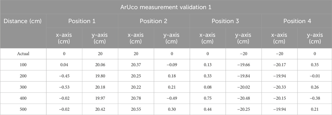
Table 1. Marker measurement trial 1.
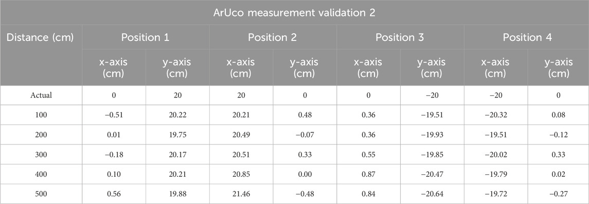
Table 2. Marker measurement trial 2.
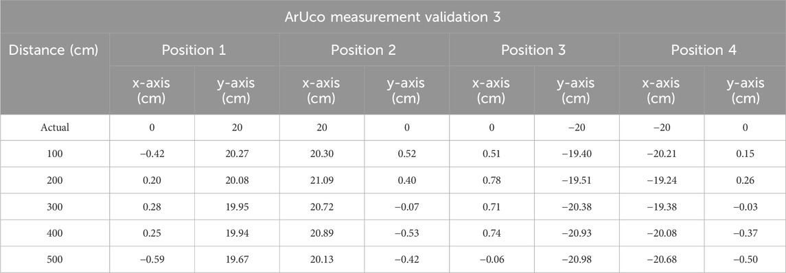
Table 3. Marker measurement trial 3.
Tables 1, 2, 3 above display the measurement values for each marker, starting with marker 1, which is positioned at the origin, followed by marker 2 to the right of the origin, marker 3 below the origin, and marker 4 to the left of the origin. The recorded values represent readings for each axis. It is evident that the measurement differences between markers at various distances are relatively minor, with an average measurement accuracy difference of 0.1 cm. This data is further illustrated in the graph shown in Figure 8 below. The experimental results indicate that the readings for each marker at distances ranging from 1 to 5 m demonstrate good accuracy, with an average measurement difference of 0.12 cm.
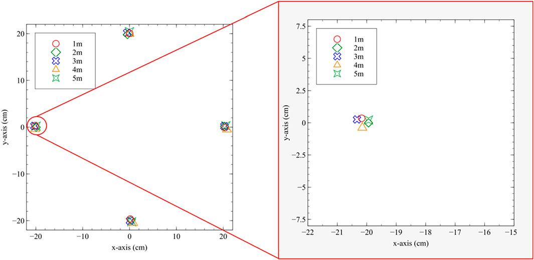
Figure 8. ArUco measurement testing result with the inset showing the enlarged portion of the data.
3.2 Straight motion and rotational motion results
Straight-line motion testing was carried out following the procedures outlined in the previous chapter. This testing was conducted on both Prototype 1 and 2. Data collection was performed ten times for each prototype, with the results showing the measured coordinates of the straight motion shown in Figure 9a.
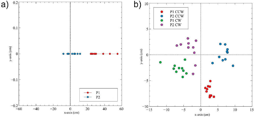
Figure 9. (a) Straight motion result and (b) Rotational motion result.
The data reveal a significant difference between Prototype 1 and Prototype 2 (t = −7.86, p-value <3.114 × 10⁻⁷). Prototype 2 demonstrates a tendency to move more straight compared to prototype 1, as indicated by the data clustering closer to the zero point. The average deviation for Prototype 2 is 5.38 cm, significantly smaller than the average deviation of 32.68 cm for Prototype 1.
Additionally, the data for Prototype 1 is compared with results from previous experiments using manual measurement methods and the results are shown in Table 4.
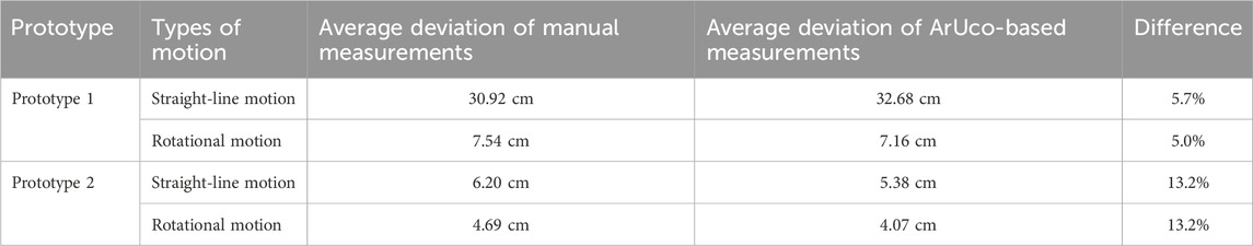
Table 4. Tabulated results comparing average deviation values of manual and ArUco-based measurements.
The rotational motion test was also carried out on both Prototype 1 and Prototype 2 following the previously outlined procedures. Data was collected ten times for clockwise rotation and ten times for counterclockwise rotation for each prototype. The result from this study is shown in Figure 9b.
When examining each axis, Prototype 2 performs significantly better along the y-axis, with data points closer to zero, while both prototypes have similar deviation values on the x-axis. The average deviation values for Prototype 1 and 2 are shown in Table 4, focusing only on CW rotation to avoid confusion. The deviation for rotational motion is defined as the Euclidian distance from the ideal center, i.e., the origin (0,0). The average deviation for clockwise (CW) rotation indicates that Prototype 2 outperforms Prototype 1, with a t-test result of t = 3.91 and a p-value <0.00356. The average deviation for CW rotation decreased from 7.16 cm to 4.07 cm.
3.3 Discussion
In straight-line motion, Prototype 1 tends to veer to the left, evident from the positive x-values in the marker data distribution shown in Figure 9a. This aligns with results from previous studies. Switching from a DC motor to a servo motor for the steering system is crucial for improving the swerve drive’s ability to maintain its direction. Several external factors can also influence the test results. These include the initial position of the hospital bed on the track and the starting position of the caster wheels, which affect how the bed initiates movement. Slippage between the floor and the wheels due to insufficient grip can lead to unwanted directional changes. Additionally, mismatched acceleration between the front and rear wheels can cause unintended direction shifts. The ability of the servo motor to maintain the steering wheel position is another critical factor.
As for the rotational motion test, several factors influenced the results of it, contributing to modest improvement as compared to straight-line performance. This may be attributed to several mechanical and control factors. First, the servo-driven steering system primarily enhances directional stability in linear motion but provides limited benefit during rotation, where both modules must coordinate angular velocity precisely. Small timing mismatches between front and rear wheel rotation, belt tension variability, or micro-slippage can accumulate and offset the intended rotational center. Also, the initial position of the hospital bed varied from one trial to another. Additionally, the alignment of the camera with the bed was not perfectly parallel, which affected measurement accuracy. Slippage between the floor and the wheels due to inadequate grip led to unwanted directional changes. Differences in the rotational speeds of the front and rear wheels, as well as discrepancies between forward and backward speeds, also contributed to inaccuracies. Furthermore, mismatched acceleration between the front and rear wheels resulted in unintended direction changes.
From the experiment conducted, it was found that the hospital bed’s ability to move in a straight line improved by 83.51%, while there was no significant change in rotational movement capability, with only a 25.02% improvement. This research aims to provide a comprehensive evaluation of the motorized hospital bed prototypes, focusing on both straight-line and rotational movement performance. By addressing the mechanical and environmental factors influencing these movements, the study seeks to develop an optimized motorized hospital bed that enhances maneuverability, reduces the physical burden on healthcare workers, and improves overall hospital efficiency.
Furthermore, as shown in Table 4, the measurements obtained from the manual method and the ArUco marker system are very close, with differences ranging from 5.0% to 13.2%. This indicates that the two methods produce generally consistent results, with minor discrepancies likely attributable to mechanical factors. Importantly, the relative performance ranking remains the same across both methods, with P2 consistently outperforming P1. Statistical analysis also suggests that the differences between the two measurement methods are not significant.
From a clinical standpoint, maintaining a straight-line deviation below approximately 10 cm is generally acceptable for safe navigation of hospital beds in corridors at moderate speed. This tolerance ensures that the bed remains centered within a standard 1.2 m-wide hospital corridor and minimizes the risk of collision with walls or equipment. The average deviation of 5.38 cm observed in Prototype 2 therefore falls within a practically safe range for patient transport, while the 32.68 cm deviation in Prototype 1 would be considered excessive and could necessitate frequent operator correction. These results highlight that improved steering precision directly contributes to both patient safety and reduction of caregiver workload.
In addition to consistency, the ArUco approach demonstrated a clear advantage in efficiency, i.e., data collection using ArUco markers required roughly one-third of the time compared to manual measurement, as observed during experiments. The ArUco-based results were also more consistent, as reduced human involvement minimized potential operator error.
Overall, these findings confirm the feasibility and accuracy of using ArUco markers to evaluate the motion performance of full-scale motorized hospital beds. This vision-based method achieved high measurement accuracy (average error ≈0.1–0.12 cm) across distances from 1 to 5 m, making it a reliable and efficient alternative to traditional manual measurement.
Beyond evaluating our own prototypes, these results offer broader implications for the robotics and healthcare engineering communities. First, the application of ArUco markers in this context demonstrates a low-cost, non-contact, and replicable method for motion tracking and path deviation analysis on large mobile systems. This is particularly valuable for research involving Motorized hospital beds and stretchers, autonomous patient transport robots, rehabilitation or eldercare mobile platforms, or industrial carts in logistics settings such as AGV.
Unlike traditional approaches that rely on encoders, IMUs, or expensive motion capture systems, ArUco marker-based tracking offers a flexible and accessible alternative that can be adapted to various environments without requiring major infrastructure or costly instrumentation. Future benchmarking against high-precision systems such as VICON motion capture, optical LIDAR localization, or IMU-based tracking would further contextualize accuracy. VICON systems typically achieve sub-millimeter spatial precision but at high installation cost, while LIDAR and IMU systems provide robustness to occlusion and dynamic lighting. A comparative assessment could quantify trade-offs between accuracy, scalability, and cost, offering a clearer comparisons.
Moreover, our results underscore the significance of scaling considerations. Much of the existing literature focuses on small-scale robotic platforms, where dynamics such as momentum, slippage, and torque response are negligible. However, when dealing with full-size systems (∼100–150 kg), these factors become critical. The proposed method captures deviations caused by such real-world dynamics, offering a practical way to benchmark and refine motion control algorithms under operational conditions. The method also facilitates repeatable and automated evaluation, reducing human error in measurement and allowing for faster iteration during prototype development. For researchers or engineers engaged in hardware validation, especially those integrating advanced drive mechanisms (e.g., swerve or omnidirectional systems), the marker-based evaluation framework presented here can serve as a template for performance benchmarking.
This study was conducted under controlled laboratory conditions with uniform lighting and a flat floor surface. In real hospital environments, additional factors such as irregular flooring, corridor obstacles, variable lighting, and reflective surfaces may affect the performance of the vision-based ArUco tracking system. Moreover, the experiments did not account for the presence of patients or additional payloads, which can introduce dynamic loading effects such as shifting centers of gravity and inertial disturbances during acceleration or turning. Marker occlusion due to medical personnel, equipment, or bed attachments (e.g., IV poles, side rails) may also reduce tracking reliability. Future tests in operational hospital corridors under varied lighting and load conditions are also needed to validate robustness and clinical readiness.
4 Conclusion
This study demonstrates the feasibility and effectiveness of using ArUco fiducial markers to evaluate the motion performance of full-scale motorized hospital beds equipped with swerve drive modules. Two prototypes were developed and tested using straight-line and rotational motion experiments. The results show that Prototype 2, which incorporates a servo-based steering mechanism and a belt-driven propulsion system, significantly outperforms Prototype 1 in maintaining straight-line trajectory, achieving an 83.51% improvement in motion accuracy. The ArUco marker-based measurement method proved to be highly accurate, time-efficient, and easy to implement, with average measurement errors of less than 0.12 cm across a 1–5 m range. Compared to manual methods or conventional sensor-based tracking systems, this vision-based approach offers a low-cost, scalable, and non-invasive alternative that is well-suited for research involving large mobile platforms. Future work may involve integrating real-time feedback using ArUco data for closed-loop control, expanding the test scenarios to include obstacle avoidance and dynamic environments, and exploring further drivetrain optimizations. Overall, this research offers both a practical validation tool and a scalable methodology that can benefit other researchers and practitioners in robotics and healthcare engineering.
Data availability statement
The raw data supporting the conclusions of this article will be made available by the authors, without undue reservation.
Author contributions
AR: Data curation, Formal Analysis, Investigation, Writing – original draft. C-WC: Supervision, Writing – review and editing. RD: Conceptualization, Funding acquisition, Resources, Supervision, Writing – review and editing.
Funding
The author(s) declare that financial support was received for the research and/or publication of this article. This research is funded by Hibah PUTI Q2 Universitas Indonesia 2023–2024 (Contract no: NKB-829/UN2.RST/HKP.05.00/2023).
Conflict of interest
The authors declare that the research was conducted in the absence of any commercial or financial relationships that could be construed as a potential conflict of interest.
Generative AI statement
The author(s) declare that Generative AI was used in the creation of this manuscript. Generative AI (ChatGPT by OpenAI) was used to assist in the preparation of this manuscript, specifically for improving the clarity, grammar, and structure of the text. The content, data analysis, and conclusions are the original work of the authors, who take full responsibility for all aspects of the manuscript.
Any alternative text (alt text) provided alongside figures in this article has been generated by Frontiers with the support of artificial intelligence and reasonable efforts have been made to ensure accuracy, including review by the authors wherever possible. If you identify any issues, please contact us.
Publisher’s note
All claims expressed in this article are solely those of the authors and do not necessarily represent those of their affiliated organizations, or those of the publisher, the editors and the reviewers. Any product that may be evaluated in this article, or claim that may be made by its manufacturer, is not guaranteed or endorsed by the publisher.
References
Acuna, R., Li, Z., and Willert, V. (2018). “MOMA: Visual Mobile marker odometry,” in IPIN 2018 - 9th international conference on indoor positioning and indoor navigation. doi:10.1109/IPIN.2018.8533685
Botta, A., and Quaglia, G. (2020). Performance analysis of low-cost tracking system for Mobile robots. Machines 8 (2), 29. doi:10.3390/MACHINES8020029
Dhelika, R., Hadi, A. F., and Yusuf, P. A. (2021). Development of a motorized hospital bed with swerve drive modules for holonomic mobility. Appl. Sci. Switz. 11 (23), 11356. doi:10.3390/APP112311356
DJB Electronic. (2024). “What is rotary encoder? Construction, working and types.” Accessed: September. 10, 2024. Available online at: https://how2electronics.com/construction-working-rotary-encoder/
Dos Santos Cesar, D. B., Gaudig, C., Fritsche, M., Dos Reis, M. A., and Kirchner, F. (2015). “An evaluation of artificial fiducial markers in underwater environments,” in MTS/IEEE oceans 2015 - genova: discovering sustainable ocean energy for a new world. doi:10.1109/OCEANS-GENOVA.2015.7271491
Garrido-Jurado, S., Muñoz-Salinas, R., Madrid-Cuevas, F. J., and Marín-Jiménez, M. J. (2014). Automatic generation and detection of highly reliable fiducial markers under occlusion. Pattern Recognit. 47 (6), 2280–2292. doi:10.1016/J.PATCOG.2014.01.005
Garrido-Jurado, S., Muñoz-Salinas, R., Madrid-Cuevas, F. J., and Medina-Carnicer, R. (2016). Generation of fiducial marker dictionaries using mixed integer linear programming. Pattern Recognit. 51, 481–491. doi:10.1016/J.PATCOG.2015.09.023
Girindra, F. G., Budiono, H. D. S., and Dhelika, R. (2023). Evaluation of assembly time of motorized wheel module for hospital bed using boothroyd-dewhurst method. J. Adv. Res. Appl. Mech. 108 (1), 27–46. doi:10.37934/ARAM.108.1.2746
Guo, Z., and Yu, H. (2016). “Development of a novel robotic omni-directional hospital bed mover for patient transfer,” in 2016 IEEE workshop on advanced robotics and its social impacts (ARSO) (IEEE), 37–42.
Gusmiah, T., Jhoni, G., Wahyudi, A., and Pradika, J. (2020). Nurse’s experience of musculoskeletal pain at kitamura clinic pontianak, West Kalimantan, Indonesia: a qualitative study. Int. J. Multidiscip. Res. Publ. (IJMRAP) 3 (4), 26–28. Available online at: http://repo.stikmuhptk.ac.id/jspui/handle/123456789/205 (Accessed: June 09, 2024).
Haward, R., G, R., and Kalyan, M. (2023). The impact of personal protective equipment on healthcare workers on COVID-19 duty in a tertiary care hospital in South India. Cureus 15 (7), 41910. doi:10.7759/CUREUS.41910
Hijikata, M., Miyagusuku, R., and Ozaki, K. (2022). Wheel arrangement of four omni wheel Mobile robot for compactness. Appl. Sci. Switz. 12 (12), 5798. doi:10.3390/app12125798
Kalaitzakis, M., Cain, B., Carroll, S., Ambrosi, A., Whitehead, C., and Vitzilaios, N. (2021). Fiducial markers for pose estimation: overview, applications and experimental comparison of the ARTag, AprilTag, ArUco and STag markers. J. Intelligent Robotic Syst. Theory Appl. 101 (4), 71–26. doi:10.1007/s10846-020-01307-9
Kotowski, S. E., Davis, K. G., and Marras, W. S. (2022). Patient handling through moving of the beds and stretchers. Int. J. Ind. Ergon. 87, 103252. doi:10.1016/J.ERGON.2021.103252
Kyrki, V., and Kragic, D. (2011). Tracking rigid objects using integration of model-based and model-free cues. Mach. Vis. Appl. 22 (2), 323–335. doi:10.1007/S00138-009-0214-Y
Leban, B., Fabbri, D., Lecca, L. I., Uras, M., Monticone, M., Porta, M., et al. (2022). Characterization of hand forces exerted during non-powered hospital bed pushing and pulling tasks. Int. J. Occup. Saf. Ergonomics 28 (2), 991–999. doi:10.1080/10803548.2020.1857081
Lee, J., Hyun, C. H., and Park, M. (2013). A vision-based automated guided vehicle system with marker recognition for indoor use. Sensors 13 (8), 10052–10073. doi:10.3390/S130810052
Morse, J. M., Gervais, P., Pooler, C., Merryweather, A., Doig, A. K., and Bloswick, D. (2015). The safety of hospital beds: ingress, egress, and in-bed mobility. Glob. Qual. Nurs. Res. 2015, 2333393615575321–20. doi:10.1177/2333393615575321
Nurhasan, S., and Hariyanto, A. (2021). Alat Pelindung Diri (APD) untuk Membantu Tenaga Medis dalam Menangani Pasien Covid-19 di Jawa Timur. Inspirasi J. Pengabdi. Dan. Pemberdaya. Masy. 1 (1), 65–73. Available online at: https://journal.inspirasi.or.id/jppm/article/view/56 (Accessed: June 09, 2024).
Oftadeh, R., Aref, M. M., Ghabcheloo, R., and Mattila, J. (2013). Mechatronic design of a four wheel steering Mobile robot with fault-tolerant odometry feedback. IFAC Proc. Vol. 46 (5), 663–669. doi:10.3182/20130410-3-CN-2034.00092
Poroykov, A., Kalugin, P., Shitov, S., and Lapitskaya, I. (2020). “Modeling ArUco markers images for accuracy analysis of their 3D pose estimation,” Proc. 30th Int. Conf. Comput. Graph. Mach. Vis. Graph. 2, 14–17. doi:10.51130/GRAPHICON-2020-2-4-14
Rabbani, A. N., Hadisujoto, B., and Dhelika, R. (2024). Motorized hospital bed for mobility of patients: a review on wheel type design. J. Eng. Appl. Sci. 71 (1), 170. doi:10.1186/s44147-024-00504-9
Romero-Ramirez, F. J., Muñoz-Salinas, R., and Medina-Carnicer, R. (2018). Speeded up detection of squared fiducial markers. Image Vis. Comput. 76, 38–47. doi:10.1016/J.IMAVIS.2018.05.004
Roos-Hoefgeest, S., Garcia, I. A., and Gonzalez, R. C. (2021). Mobile robot localization in industrial environments using a ring of cameras and ArUco markers. IECON Proc. Ind. Electron. Conf. 1–6. doi:10.1109/IECON48115.2021.9589442
Rosebrock, A. (2024). “Detecting ArUco markers with OpenCV and python - PyImageSearch.” Accessed: June. 09, 2024. Available online at: https://pyimagesearch.com/2020/12/21/detecting-aruco-markers-with-opencv-and-python/
Keywords: hospital bed, motorized hospital bed, swerve drive, omnidirectional, automation, robotics
Citation: Rabbani AN, Chen C-W and Dhelika R (2025) A scalable vision-based method for motion assessment of full-scale motorized hospital beds using ArUco markers . Front. Mech. Eng. 11:1627308. doi: 10.3389/fmech.2025.1627308
Received: 12 May 2025; Accepted: 17 October 2025;
Published: 29 October 2025.
Edited by:
Mohamed Arezki Mellal, University of Boumerdés, AlgeriaReviewed by:
Paolo Di Giamberardino, Sapienza University of Rome, ItalyŞenay Mihcin, Izmir Institute of Technology, Türkiye
Copyright © 2025 Rabbani, Chen and Dhelika. This is an open-access article distributed under the terms of the Creative Commons Attribution License (CC BY). The use, distribution or reproduction in other forums is permitted, provided the original author(s) and the copyright owner(s) are credited and that the original publication in this journal is cited, in accordance with accepted academic practice. No use, distribution or reproduction is permitted which does not comply with these terms.
*Correspondence: Radon Dhelika, cmFkb25AZW5nLnVpLmFjLmlk