 Kartikeya Walia
 William Navaraj
 Philip Breedon
- Department of Engineering, School of Science and Technology, Nottingham Trent University, Nottingham, United Kingdom
A singularity-free pose realization is a key feature for any robotic system. This paper presents the development of a 3-DoF pure rolling spherical parallel manipulator (SPM) with tightly integrated actuators. Conventional serial wrist mechanisms often face singularities and structural constraints, limiting performance during dynamic tasks. They also require more space due to their larger span. While parallel manipulators are compact, they often concentrate weight in a confined volume and offer limited room for actuator integration. To address these challenges, we propose a pure rolling spherical parallel manipulator (SPM) that incorporates generative design for weight optimization, reducing overall mass while preserving structural integrity and manipulability. This approach achieved a 54.61% reduction in linkage weight and a 33.9% reduction in total system-weight, enabling compact and efficient integration of direct or quasi-direct drive actuators. The mechanism’s unique topology allows pure rolling motion with decoupled yaw control, overcoming limitations of existing 2-DoF devices like Omni Wrist III. Using 3D printing for prototyping facilitated rapid iterations and testing. Performance evaluation demonstrated high precision, with mean positional errors of 0.0291 mm–0.2778 mm and orientation errors between 0.0562° and 0.3561°. Validated as a neck joint for an immersive teleoperated robot, the SPM shows promise in humanoid robotics and advanced manipulation requiring precise orientation control. The integration of actuators within a generatively optimized structure offers a compact, lightweight solution and a high-performance alternative for applications demanding singularity-free motion and reduced actuation-complexity. Future work will extend this design to higher payload systems using metal components, enhancing durability and functionality for industrial applications.
1 Introduction
The problem of achieving a desired orientation in 3D space requires a 3 Degrees-of-Freedom (DoF) mechanism. There are broadly 2 basic configurations possible for the articulation, i.e., serial and parallel. Serial mechanism is relatively simple, reliable and used widely as wrists in most industrial use cases in anthropomorphic robot arms, but they suffer from singularities under certain poses and the cantilevered structure with load at the end makes them susceptible to bending and vibration issues (Bäuml et al., 2014).
Serial design when extended also tends to have a larger span and volume and will require more room for operating, which makes it undesirable for compact applications. Parallel structures are compact and therefore are frequently used for wearable devices (Higuma et al., 2017), surgical instruments (Hong and Jo, 2013) and lightweight robotic humanoid arms (Kim et al., 2018). Parallel manipulators while compact have a larger weight concentrated within a minimal volume. Most prior designs have less room for integrating actuators. The latter is often addressed by adding actuators and transmission systems externally to the structure (He et al., 2021). This approach increases complexity and makes the design and structure cumbersome and bulky, ultimately defeating the purpose of a compact design. Some of them use complex transmission systems involving indirect actuation, like belt (Enferadi and Jafari, 2020) or cable-driven transmission and the requirement of additional tension amplification mechanisms and a complicated kinematic relationship (Kim et al., 2018; Grebenstein et al., 2012).
The Omni Wrist III (OW), invented by Rosheim and Ross Hime Designs Inc (1999) and Rosheim and Sauter (2002), is a gimbal-like free space optical sensor mount. High angles of azimuth and declination and a singularity-free range of motion are the characteristic features of this innovative design. Originally, developed as a sensor pointing device in collaboration with the U.S. Air Force it was proposed as an alternative to the existing antenna pointing mechanisms namely, Schaffer Biaxial Drive and Honeywell Mount.
The latter two designs have a singularity problem, during the gimbal lock when the Joint 2 axis (Pitch-actuation) aligns with the Joint 1 axis (Roll actuation). Consequently, Roll becomes Yaw, and the resultant singularity complicates the control. These devices are representative of an existing 2 DoF robotic serial manipulator and inherit its drawbacks in the applications involving reorientation of the end-effector. Singularity free manipulators are desirable particularly for autonomous application where the robot may compute and come up with prior untested trajectory while performing various tasks. If such trajectories involve kinematic singularity it may affect safe operation and can lead to unpredictable and dangerous motion, injuries or damage to the robot and the surroundings.
Both 3 and 4-leg implementations of the Omni Wrist (3-OW and 4-OW) have been studied in the literature, by Ghaedrahmati and Gosselin (2022) and Chang-Siu et al. (2022) respectively. Although theoretically, any n-legged (n > 2 and n ∈ N) variant is possible, practically a two legged version will be under-constrained and five or more equally spaced legs will restrict the motion due to self-collisions because of insufficient design space.
A 2-DoF singularity-free alternative to the Omni Wrist, called the Quaternion Joint, was invented by Lande and David (1981). It was further developed by Kim et al. (2018) claiming Omni Wrist to be unsuitable for accommodating in a manipulator due to its large size and link interference.
Spherical Parallel Manipulators (SPMs), like the Omni Wrist and the Quaternion Joint, incorporate parallel links with N-double universal legs (N-UU) and a singularity-free operation over the entire or partial hemispherical workspace. These are also classified as homokinetic joints (Dong et al., 2012) (explained later in Section 2.2) as the 2-DoFs provide the freedom to spatially orient without spinning. A pure rolling homokinetic or a constant velocity joint provides a zero-torsion (Wu and Carricato, 2019) operation and hence no yaw motion is possible along the axis of the end-effector. The mechanism presented in this work is a subset of spherical parallel manipulators, characterised by its homokinetic joint topology which enables pure rolling motion and eliminates torsional coupling. While the precise classification is a pure rolling spherical parallel manipulator, for brevity, it is referred to as SPM throughout this paper.
The current limitations in orientation control stem from designs restricted to 2° of freedom or reliant on complex transmission systems such as cables, shafts, or gears for an extra degree of motion. These add weight and bulkiness, making them unsuitable for many robotic applications. Additionally, intricate systems with numerous moving parts increase the risk of failure, hence the preference for direct actuation. This paper presents a 3D printed 4-legged SPM with 3-DoF accommodating all the actuators within its compact design. The extra (third) degree-of-freedom is owed to the additional yaw motion possible, independent of the spherical cone tilt-motion (roll and pitch). Utilising generative design and topology optimisation (Section 4), the linkage design was optimised to enable integration of actuators within the body of the mechanism. This approach effectively reduced part weight, facilitating the direct integration of additional actuators at the joints. A proof-of-concept prototype was designed, developed, and fabricated and the motion was analysed using a MetaMotionR inertial measurement unit (IMU) sensor. Furthermore, a demonstration was conducted employing the developed mechanism as the neck of an immersive teleoperated robot.
2 Design features
2.1 Joint mechanism
As shown in Figure 1, the mechanism is embodied with 4 linkage systems between the input and the output segments. Each linkage system consists of 3 links, namely, an input link, an intermediate link, and an output link coupled with four rotation pairs in total. Each rotation pair accommodates a bearing to eliminate clearance at the links and reduce rotational resistance.
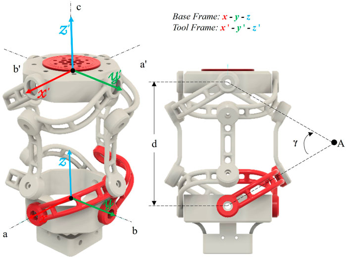
Figure 1. Axes of motion (left) and characteristic variables (right).
The output segment also accommodates a third independent degree-of-freedom which allows for a roll motion without violating the zero-torsion (Bonev, 2008) characteristic of the mechanism.
2.2 Operating principle
Figure 1 shows a labelled illustration of the design. The frame formed by the x-y-z axes is the Base Frame and the Tool Frame is described by the x′-y′-z′ axes. The origins of the Base and the Tool Frame lie at the centroids of the input and output segments of the design, respectively. There are 4 linkage systems connecting the Input and the Output segments. Each linkage system forms a spherical link mechanism as the segments move on a spherical surface. The input and the output links’ axes connecting to the intermediate link, if extended, meet at a certain crossing angle (angle γ, Figure 1). The linkage system is symmetric to Point A (Figure 2) and the angle subtended (γ) is crucial to the operation of the mechanism and drives the aspect ratio of the structure.
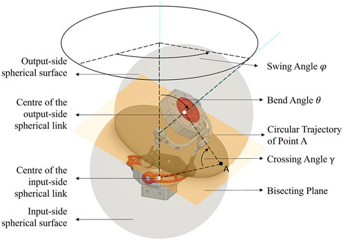
Figure 2. Operating Principle.
The two driving links (active input links) are highlighted in red, and the opposite links (passive input links) are mechanically coupled with them to drive passively. The linkage systems are equally spaced (90° apart) and are constrained to move on a common circle. As a result, Point A always lie on the homokinetic plane bisecting the centre lines of the input and the output segments (Figure 2). In Figure 1, the torque at axis a is transmitted to axis a′ and similarly from axis b to axis b′ via the linkage mechanism, and hence the homokinetic behaviour is observed. The axis a, b and c correspond to the shaft axes of the 3 driving actuators (active joints), respectively.
3 Kinematics
Several different approaches have been utilised to perform a comprehensive kinematic analysis for this type of mechanism in the literature. Chang-Siu et al. (2022) used an analytical geometric approach, Yu et al. (2012) used screw theory and Sofka et al. (2006a) employed the Denavit-Hartenberg approach to derive the Forward and Inverse Kinematic relationships. Siu’s results provide a concise representation of the Omni Wrist’s kinematics as a function of the active joint angles that can be readily implemented in simulation. These have been modified for a 3-DoF mechanism and are presented below. Figure 3 represents a simplified version of the 3-DoF SPM and the work envelope for an easy-to-understand visualisation.
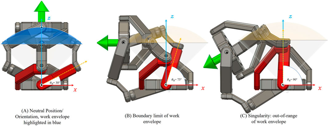
Figure 3. Visualisation of workspace and singularity condition for the SPM. (A) Neutral position with the full work envelope highlighted in blue. (B) Boundary limit of motion when the input angle θB approaches 75°, nearing the maximum operational range. (C) Singularity condition at θB = 90°, where the input link becomes vertically aligned with the Z-axis. This position causes Δ → 0 in the forward kinematics, leading to a kinematic singularity that lies outside the defined workspace due to mechanical joint constraints.
3.1 Nomenclature
q represents the set of active joint angles, where θA1 and θB1 corresponds to the angles from the nominal of the two driven legs of the base links while θC corresponds to the driven angle of the final end-effector as shown in Equation 1. θA and θB represents the angle of the input link from the horizontal plane, as shown in Equation 2. The convention used here is similar to Chang-Siu et al. (2022) with consideration for an extra degree-of-freedom, thanks to the third compactly integrated actuator (yaw). It is to be noted that the axes consideration corresponds to the application of this mechanism for a robotic neck joint (Z-up, X-front).
Due to the characteristic spherical constraint (spherical sector in Figure 3) of the mechanism, the axial vector p (Equation 3) has a constant magnitude d (Equation 4). The vector p represents the origin of the Tool Frame at any instant.
3.2 Forward kinematics
In the equations below, the sine and cosine of an angle, θn, are replaced by sθn and cθn for conciseness. To simplify the forward kinematics expressions, two auxiliary variables, σ1 and σ2, are introduced. These serve to condense repeated trigonometric expressions for ease of computation:
where,
These expressions are used in Equation 5 for calculating the tool frame position. The position, p, of the tool frame is given by,
where,
∆ = 0 when θA and θB = ±90° (Figure 3) which corresponds to either of the input links aligned to the vertical axis of the mechanism. This situation occurs outside of the hemispherical workspace and has boundary constraints by the existing joint limits and the choice of γ. Therefore, this singularity at the edge of the hemisphere lies outside the workspace envelope. It can be noted that θC, does not appear in Equation 5 and therefore, has no effect on the spatial position p of the tool frame.
The rotation, R, of the tool frame w.r.t. the base frame, parameterised by p and θC is given by Equation 6,
where,
Clearly, the third active joint (θC) provides an independent and decoupled yaw motion along the axis z′ in the kinematics of the mechanism.
3.3 Inverse kinematics
The inverse kinematics problem involves determining the actuator inputs θA1, θB1 and θC corresponding to a desired end-effector pose, given by a position vector p ∈ ℝ3 on a spherical surface of radius ‘d’, and a desired yaw angle θC. Due to the decoupled nature of the yaw axis, θC can be directly set as the desired value without affecting the spatial position.
To compute θA1 and θB1, invert the forward kinematic relation given in Equation 5. This relation expresses p as a nonlinear function of θA and θB where Equation 2 can be substituted.
An analytical inversion of this system is feasible, though algebraically intensive. Alternatively, for practical implementation, a numerical solution using tools such as MATLAB’s fsolve or symbolic solvers can be used to compute θA and θB from p, which are then converted back to actuator inputs. Due to the symmetrical and well-constrained geometry, the solution is unique within the manipulator’s hemispherical workspace and avoids ambiguities present in general SPMs.
This inverse model is suitable for real-time control and mapping from teleoperated motion, such as head or neck movement, to actuator angles. Future work will implement a full closed-loop control system using these mappings.
4 Design optimisation
All the design constraints and requirements of a spherical parallel manipulator were considered with additional constraints like mass optimisation, cable management, utilizing off-the-shelf electronics and enabling enough volumetric space for accommodating all the actuators for a direct drive mechanism. Following are the design specifications:
• Spatially arranged spaced linkage segments at an equal angular spacing of 90°.
• An axial distance, d = 110 mm, specifying the overall length of the mechanism. It does not account for the structural thickness, but it drives the aspect ratio of the design.
• The Cross-link subtended angle γ = 60°. Previous works Sofka et al. (2006b) and Shah et al. (2018) show that a reasonable choice of γ is around 45° for good mobility.
• Three Dynamixel XH430-V350 actuators were used to provide a high torque density and smaller footprint. Additionally, Daisy-chaining allows for better cable management.
• 14 x 625-2RS bearings were used at every passive rotational pair and a 6807-RS bearing was used at the yaw-axis.
Weight optimisation was an essential aspect of the design to compensate for the additional mass of the consolidated actuators in the assembly. Rib and Gussets were incorporated in the input and the output segments to reduce weight and maintain structural rigidity. Generative optimisation was used to redesign the linkage systems. This topology optimisation method only requires certain parts of the design (Walia et al., 2021a) to be designed by the user that are essential for the mountings of other components in the assembly.
Autodesk Fusion 360s Generative Design environment was used to minimize mass while preserving the structure’s ability to withstand a target load of 500 g. This value was chosen based on the application requirements and experimental validation. Therefore, no increase in load capacity was expected, but the redesign ensures equivalent mechanical performance with significantly reduced weight.
For the generative design setup, each of the four linkage segments—comprising input, intermediate, and output links—was individually optimized while preserving their functional constraints. Each link was constrained at one rotational end to simulate the fixed pivot connection within the assembly. At the opposite end, a moment load of 0.1 N·m and a force of 10 N were applied along the respective axis of rotation. These values were selected based on the target payload of 500 g (≈4.905 N), distributed across the mechanism, and reflect a conservative estimate of the maximum moment and force experienced by each linkage in operation. The applied 100 N·mm torque per linkage accounts for the cumulative moment of approximately 270 N·mm that would act at the tool centre point under worst-case conditions, distributed across the multiple supporting links. This setup ensured that each segment was structurally optimised to withstand its local loading while contributing to the overall stiffness and performance of the manipulator.
Figure 4 shows the loading conditions and constraints along with the parts highlighted in green, called preserves. Additionally, some information was required in terms of obstacles for the design (red) and optionally a starting shape (yellow). Following this the mechanical constraints and loads were applied, factor of safety was defined and the material was assigned for the fabrication through additive manufacturing. The designs were computationally formed and evaluated, and a number of valid designs were generated. Designs were compared to the other on basis of FEA results, and characteristic parameters like mass, maximum deformation and maximum factor of safety and the best outcome was accepted for fabrication and assembly. All components were additively manufactured using Acrylonitrile Butadiene Styrene (ABS) P430 material on a Stratasys uPrint 3D Printer. Material selection was done using a ‘Suitability Matrix’ (Walia et al., 2021b).

Figure 4. Generative Design study setup (left), input (middle) and outcomes (right).
The Yaw and Pitch axes of the SPM are directly driven, and Roll is a Quasi Direct Gear Drive with a 1:1 transmission ratio as shown in Figure 5. A labelled diagram of the internal components is given in Figure 6.
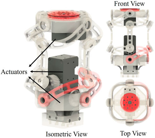
Figure 5. SPM assembly with internal components and multiple views.
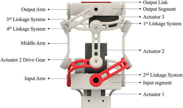
Figure 6. SPM with labelled components.
5 Simulation and experiment
Figure 7 shows the two input trajectories ((a) Cross Motion (27 s) and (b) Octagonal Motion (24 s)) which were generated to actuate the input arm linkages along with the observed orientation angles. The two motions are also presented in the Supplementary Video. To study the impact of roll and pitch on the yaw axis, no actuation was provided to the third actuator. The generated trajectories traverse a trajectory over the hemispherical work envelope of the SPM. It should be noted that the yaw is along the Z-axis, roll is along the X-axis and pitch is about the Y-axis as depicted in Figure 1. These plots also show that a yaw motion is inherently present due to the θA and θB input angles. This undesired yaw motion can be compensated and controlled using the decoupled 3rd actuator in the developed mechanism presented in this paper.
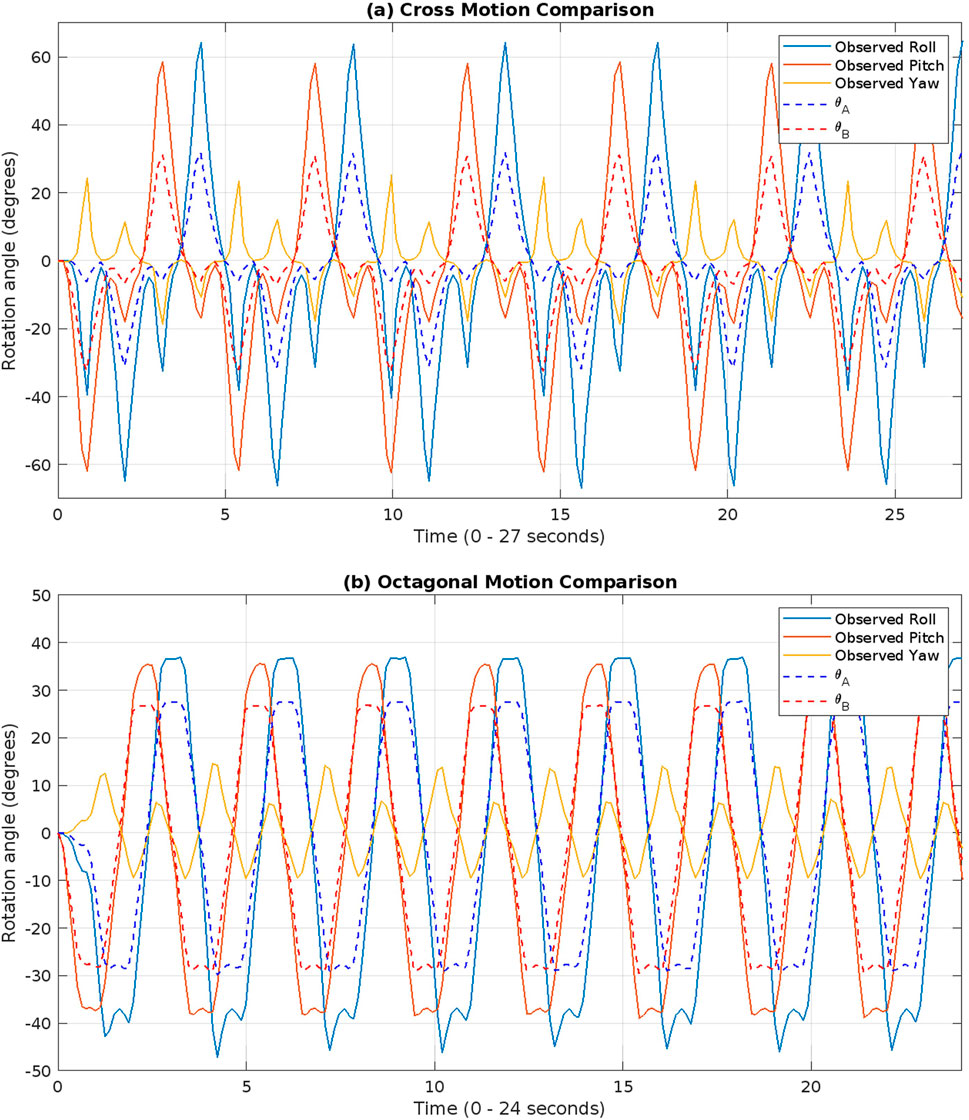
Figure 7. Input and Observed motion profiles for (a) Cross motion and (b) Octagonal motion.
A 10-axis Inertial Measurement Unit (IMU), MetaMotion by MBIENTLAB, was used to connect wirelessly and to store and transmit data via Bluetooth. A wireless capability proved to be useful in terms of avoiding additional cables and microcontrollers and keeping the SPM assembly simple. This also provides for a possibility of real-time data monitoring and using it to create a closed-loop control system. For the experiment, it was used to record the data and process it later by syncing the timestamps of the collected data and the simulation.
Figures 8, 9 show the time filmstrip of the observed cross and octagonal motion respectively. The same motion was repeated multiple times to observe any discrepancy in repeatability and to observe hysteresis effects.
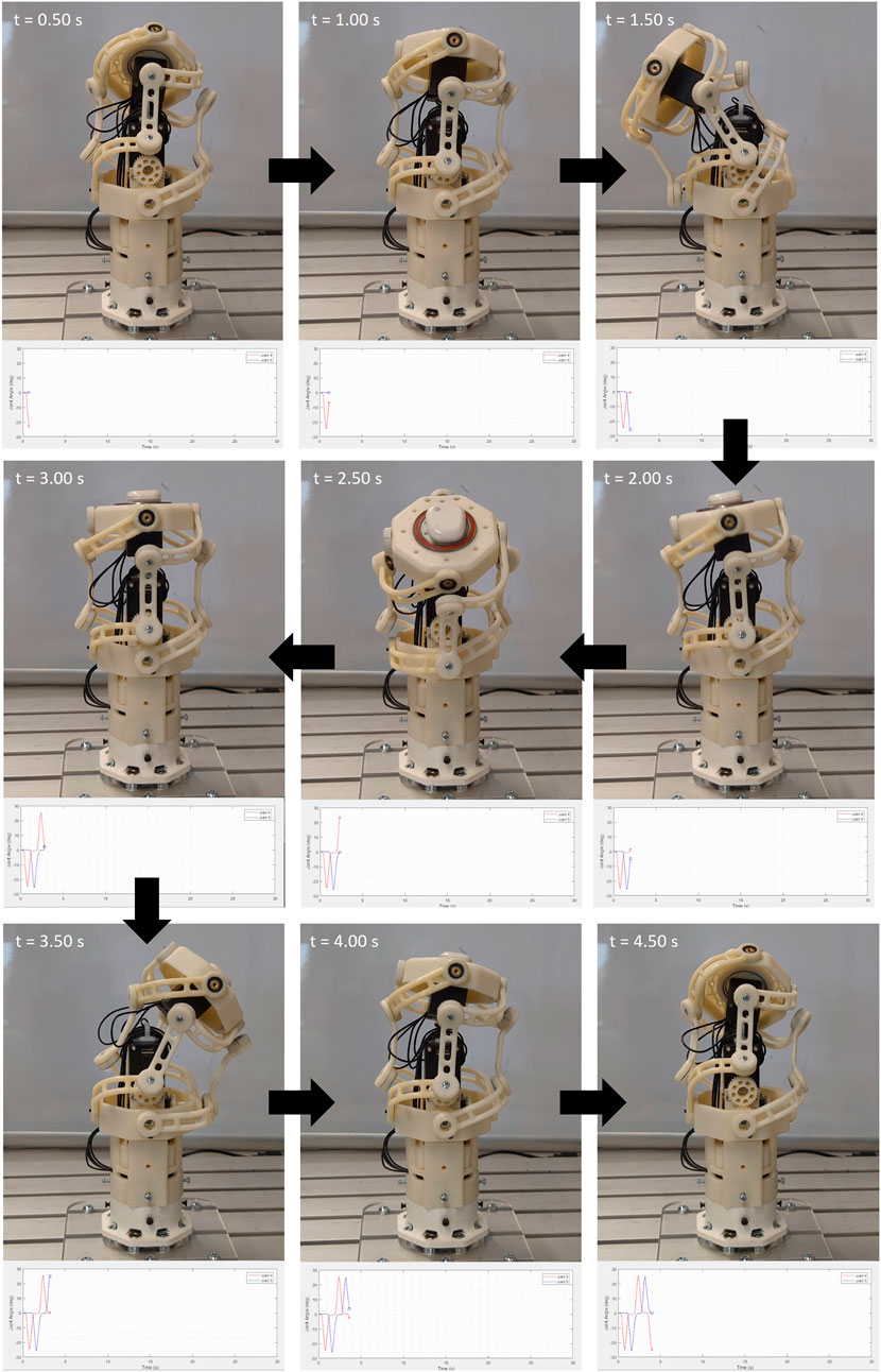
Figure 8. Four and half seconds filmstrip for cross motion.
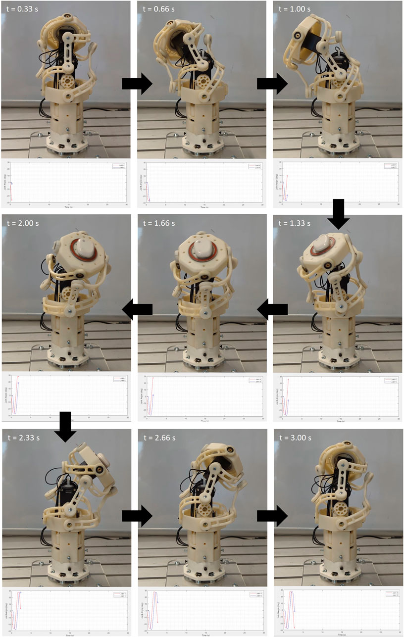
Figure 9. 3 s filmstrip of the octagonal motion.
The orientation values (roll, pitch, yaw) required for the pose estimation of the SPM were obtained from the IMU data. Furthermore, the kinematics equations derived in Section 3 were used to calculate the position values for the pose.
6 Results and discussion
Both, cross and octagonal, trajectories were plotted in the 3D task space and are illustrated in Figures 10, 11 respectively.
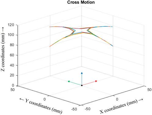
Figure 10. Observed Cross motion.
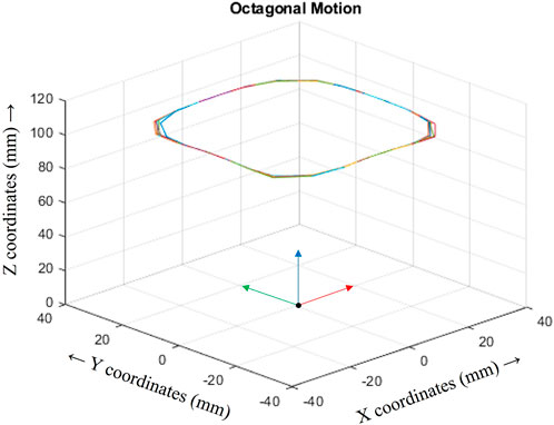
Figure 11. Observed Octagonal motion.
The analysed standard deviation of means (SDM, a measure of repeatability error) shown in Table 1, calculated using Equation 7, provide the values for the calculated Repeatability Coefficients (RC) for the task space coordinates namely, px, py, pz, roll, pitch, and yaw at the Tool Centre Point (TCP) for both the cross and the octagonal motion.
where,
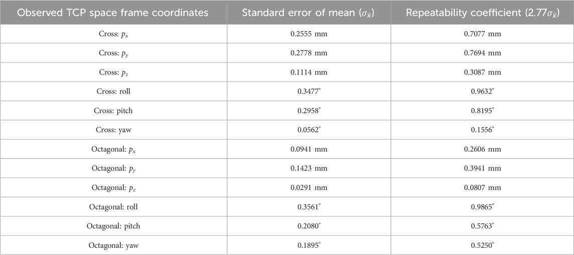
Table 1. Repeatability results for SPM.
The repeatability coefficient (RC) is a value such that, the difference between two observations of the same object taken under the same conditions will be less than the RC in 95% of instances (ISO 5725-6:1994 ed. International Organization for Standardization, 1994). This is given by the relation in Equation 8,
A smaller value of RC is preferable as it shows that the difference between any 2 samples will be less than the RC. This methodology helps in determining the repeatability of the mechanism. The accuracy of the system is simply the deviation between the desired and the reached value. This can be easily corrected by compensating by gain values during control. A better approach is to use a closed-loop control system.
The mean (
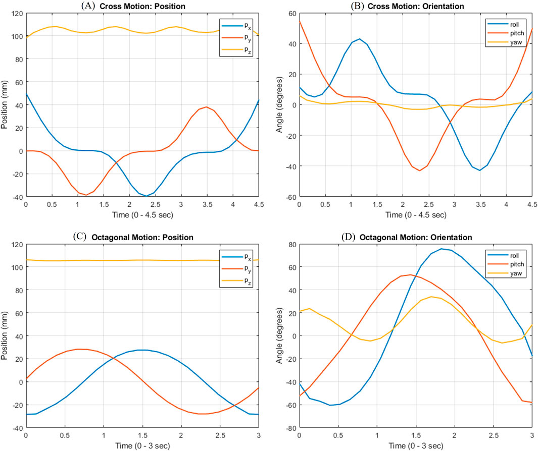
Figure 12. Task-space Tool Centre Point (TCP) pose values- (A) Cross Motion: Position, (B) Cross Motion: Orientation, (C) Octagonal Motion: Position, (B) Octagonal Motion: Orientation.
Figure 13 shows the 60 s filmstrip demonstration of the SPM as a neck joint for an immersive teleoperated robot. Figures 14, 15 shows an evident decrease in the volume of the components which resulted in a weight reduction of 54.61% (from 402 g to 182.5 g). An overall weight reduction of 33.9% (648.12g–428.5 g) was observed in the optimised iteration of the SPM assembly, compensating for the added mass of the integrated actuators (each actuator weighing 82 g (Robotis, 2018) constituting to 246 g of the total assembly weight).
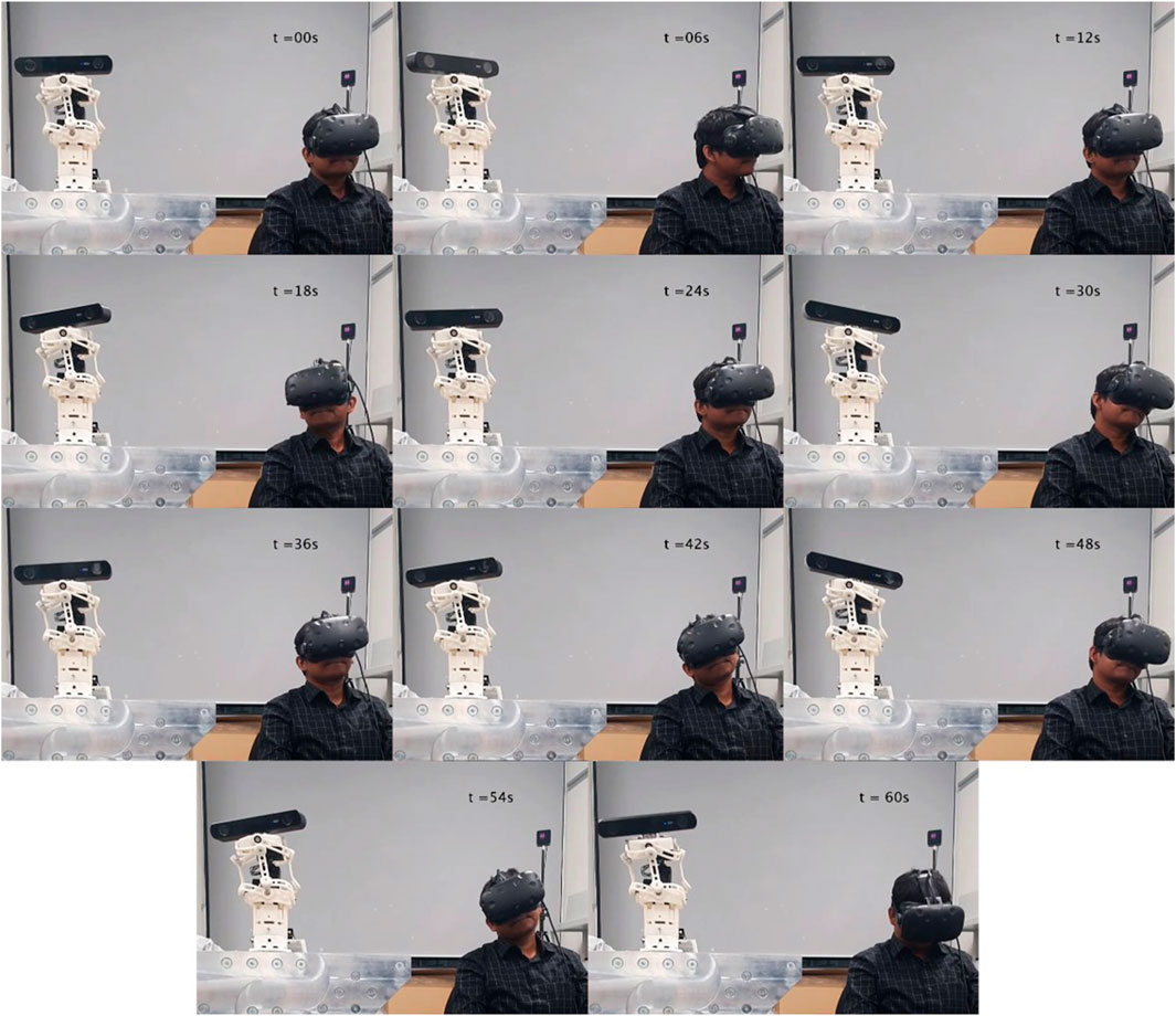
Figure 13. 60-s Teleoperation filmstrip. (The participant depicted in this figure has provided informed consent for publication).
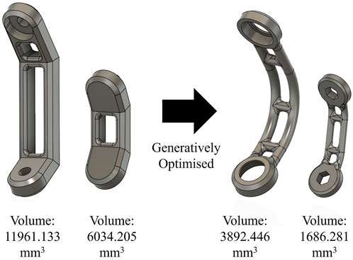
Figure 14. Volume reduction of 67.5% and 72% following Generative Design for the Middle and Input and Output arms.
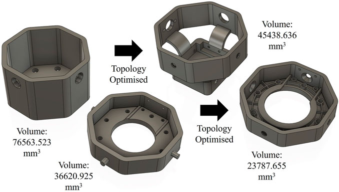
Figure 15. Volume reduction of 40.6% and 35% following Topology Optimisation for the Input and Output segment.
In the experimental setup, a ZED 2i stereo camera was mounted on the end-effector as a payload, along with a custom bracket and associated fasteners. The total weight of this configuration was approximately 230 g, which is within the designed payload limit. While the generative design was carried out to accommodate up to 500 g of payload with a safety factor of 3, the experimental payload represents a realistic, functionally demanding load scenario. The successful operation under this load condition confirms the structural integrity and practical performance of the mechanism within its intended use envelope.
7 Conclusion
The development of the SPM provides a lightweight and compact solution for a spherical wrist of an industrial robotic manipulator. Compared to the current analogous solutions, the key advancements includes the integration of all the actuators within the assembly, the direct drive or quasi-direct drive nature of all the 3 joints and the utilisation of generative optimisation for weight optimisation. The future work includes the development of a high payload manipulator using metal linkages.
The characteristic torsion-free motion of the pure rolling mechanism formed by the parallel linkage systems and a decoupled 3rd joint is particularly valuable for expanding the scope of manipulator development with allowing improved manipulability. The developed mechanism also has applications in humanoid robotics and other fields of research where precise control over the orientation of the end effector is necessary.
Data availability statement
The raw data supporting the conclusions of this article will be made available by the authors, without undue reservation.
Author contributions
KW: Conceptualization, Investigation, Methodology, Validation, Visualization, Writing – original draft, Writing – review and editing. WN: Conceptualization, Methodology, Software, Writing – review and editing. PB: Supervision, Writing – review and editing.
Funding
The author(s) declare that financial support was received for the research and/or publication of this article. This work was supported by Nottingham Trent University and PepsiCo International. This work was partly supported by Innovate UK (Grant number: 10109529) under Horizon Europe guarantee funding.
Acknowledgments
Authors would like to acknowledge the Ahmad Khan of PepsiCo International, Leicester, LE4 1 ET, United Kingdom for his guidance, feedback and supervision during the research project.
Conflict of interest
The authors declare that the research was conducted in the absence of any commercial or financial relationships that could be construed as a potential conflict of interest.
Generative AI statement
The author(s) declare that no Generative AI was used in the creation of this manuscript.
Publisher’s note
All claims expressed in this article are solely those of the authors and do not necessarily represent those of their affiliated organizations, or those of the publisher, the editors and the reviewers. Any product that may be evaluated in this article, or claim that may be made by its manufacturer, is not guaranteed or endorsed by the publisher.
Supplementary material
The Supplementary Material for this article can be found online at: https://www.frontiersin.org/articles/10.3389/fmech.2025.1629405/full#supplementary-material
References
Bäuml, B., Hammer, T., Wagner, R., Birbach, O., Gumpert, T., Zhi, F., et al. (2014). “Agile Justin: an upgraded member of DLR's family of lightweight and torque controlled humanoids,” in 2014 IEEE international conference on robotics and automation (ICRA) (IEEE), 2562–2563.
Bonev, I. A. (2008). “Direct kinematics of zero-torsion parallel mechanisms,” in 2008 IEEE international conference on robotics and automation (IEEE), 3851–3856.
Chang-Siu, E., Snell, A., McInroe, B. W., Balladarez, X., and Full, R. J. (2022). How to use the Omni-Wrist III for dexterous motion: an exposition of the forward and inverse kinematic relationships. Mech. Mach. Theory 168, 104601. doi:10.1016/j.mechmachtheory.2021.104601
Dong, X., Yu, J., Chen, B., and Zong, G. (2012). Geometric approach for kinematic analysis of a class of 2-DOF rotational parallel manipulators. Chin. J. Mech. Eng. 25 (2), 241–247. doi:10.3901/cjme.2012.02.241
Enferadi, J., and Jafari, K. (2020). A Kane’s based algorithm for closed-form dynamic analysis of a new design of a 3RSS-S spherical parallel manipulator. Multibody Syst. Dyn. 49 (4), 377–394. doi:10.1007/s11044-020-09736-y
Ghaedrahmati, R., and Gosselin, C. (2022). Kinematic analysis of a new 2-DOF parallel wrist with a large singularity-free rotational workspace. Mech. Mach. Theory 175, 104942. doi:10.1016/j.mechmachtheory.2022.104942
Grebenstein, M., Chalon, M., Friedl, W., Haddadin, S., Wimböck, T., Hirzinger, G., et al. (2012). The hand of the DLR hand arm system: designed for interaction. Int. J. Robotics Res. 31 (13), 1531–1555. doi:10.1177/0278364912459209
He, P., Kantu, N. T., Xu, B., Swami, C. P., Saleem, G. T., and Kang, J. (2021). A novel 3-RRR spherical parallel instrument for daily living emulation (SPINDLE) for functional rehabilitation of patients with stroke. Int. J. Adv. Robotic Syst. 18 (3), 17298814211012325. doi:10.1177/17298814211012325
Higuma, T., Kiguchi, K., and Arata, J. (2017). Low-profile two-degree-of-freedom wrist exoskeleton device using multiple spring blades. IEEE Robotics Automation Lett. 3 (1), 305–311. doi:10.1109/lra.2017.2739802
Hong, M. B., and Jo, Y. H. (2013). Design of a novel 4-DOF wrist-type surgical instrument with enhanced rigidity and dexterity. IEEE/ASME Trans. mechatronics 19 (2), 500–511. doi:10.1109/tmech.2013.2245143
ISO 5725-6:1994 ed. International Organization for Standardization (1994). Accuracy (trueness and precision) of measurement methods and results Part 6: use in practice of accuracy values. Available online at: https://www.iso.org/standard/11837.html (Accessed July 17, 2023).
Kim, Y. J., Kim, J. I., and Jang, W. (2018). “Quaternion joint: dexterous 3-dof joint representing quaternion motion for high-speed safe interaction,” in 2018 IEEE/RSJ international conference on intelligent robots and systems (IROS) (IEEE), 935–942.
Lande, M. A., and David, R. J. (1981). Association des Ouvriers en Instruments de Precision, Articulation for manipulator arm. U.S. Patent 4,300,362. Available online at: https://patents.google.com/patent/US3610438A/en
Robotis (2018). Robotis e-manual:XH430-v210. Available online at: https://emanual.robotis.com/docs/en/dxl/x/xh430-v210 (Accessed July 14, 2023).
Rosheim, M. E.Ross Hime Designs Inc (1999). Multiple rotatable links robotic manipulator. U.S. Pat. 5 (893), 296. Available online at: https://patents.google.com/patent/US5893296A/en
Rosheim, M. E., and Sauter, G. F. (2002). New high-angulation omnidirectional sensor mount. Free-space laser Commun. laser imaging II 4821, 163–174. doi:10.1117/12.465912
Shah, D., Metta, G., and Parmiggiani, A. (2018). Workspace analysis and the effect of geometric parameters for parallel mechanisms of the N-UU class. Int. Des. Eng. Tech. Conf. Comput. Inf. Eng. Conf. 51807, V05AT07A029. doi:10.1115/detc2018-85258
Sofka, J., Skormin, V., Nikulin, V., and Nicholson, D. J. (2006a). Omni-Wrist III - a new generation of pointing devices. I. Laser beam steering devices - mathematical modeling. IEEE Trans. Aerosp. Electron. Syst. 42 (2), 718–725. doi:10.1109/taes.2006.1642584
Sofka, J., Skormin, V., Nikulin, V., and Nicholson, D. J. (2006b). Omni-Wrist III - a new generation of pointing devices. II. Gimbals systems - control. IEEE Trans. Aerosp. Electron. Syst. 42 (2), 726–734. doi:10.1109/taes.2006.1642585
Walia, K., Khan, A., and Breedon, P. (2021a). The generative design process for robotic design applications. J. Addit. Manuf. Technol. 1 (2). doi:10.18416/JAMTECH.2111528
Walia, K., Khan, A., and Breedon, P. (2021b). Polymer-based additive manufacturing: process optimisation for low-cost industrial robotics manufacture. Polymers 13 (16), 2809. doi:10.3390/polym13162809
Wu, Y., and Carricato, M. (2019). Workspace optimization of a class of zero-torsion parallel wrists. Robotica 37 (7), 1174–1189. doi:10.1017/s0263574718000413
Keywords: generative design, teleoperated robot, spherical parallel manipulator, omni-wrist, quasi direct drive
Citation: Walia K, Navaraj W and Breedon P (2025) Generatively optimised compact 3-DoF spherical parallel manipulator with tightly integrated actuators. Front. Mech. Eng. 11:1629405. doi: 10.3389/fmech.2025.1629405
Received: 15 May 2025; Accepted: 20 June 2025;
Published: 11 July 2025.
Edited by:
Hamid Reza Karimi, Polytechnic University of Milan, ItalyReviewed by:
Wenpei Zhu, Southern University of Science and Technology, ChinaBalaji Veerasamy, PSG College of Technology, India
Yulin Zhou, Yanshan University, China
Copyright © 2025 Walia, Navaraj and Breedon. This is an open-access article distributed under the terms of the Creative Commons Attribution License (CC BY). The use, distribution or reproduction in other forums is permitted, provided the original author(s) and the copyright owner(s) are credited and that the original publication in this journal is cited, in accordance with accepted academic practice. No use, distribution or reproduction is permitted which does not comply with these terms.
*Correspondence: Kartikeya Walia, a2FydGlrZXlhLndhbGlhQG50dS5hYy51aw==