 Hongtao Dong
 Yang Zhang3
- 1College of Mechanical and Electrical Engineering, Central South University, Changsha, Hunan, China
- 2AECC Hunan Aviation Powerplant Research Institute, Zhuzhou, Hunan, China
- 3State Key Laboratory of Mechanical Transmission for Advanced Equipment, Chongqing University, Chongqing, China
Gear contact behavior significantly influences system vibration, wear, and transmission efficiency. Among the factors governing this, contact deformation, flash temperature, and meshing stiffness are particularly critical. For complex tooth surfaces, especially under localized contact conditions, only partial regions engage during meshing, making the spatial distribution of mechanical and thermal parameters essential. This study presents a spatially resolved analysis of contact deformation, stiffness, and flash temperature in involute gear pairs, including spherical involute surfaces commonly found in bevel gears. By examining tangential velocity and deformation characteristics across the meshing region, the study quantifies stiffness and flash temperature distribution over the tooth surface. The interdependence of these variables is also investigated. The study’s results offer parameter-level references to support the informed selection of contact paths, especially where empirical or experience-based decisions dominate in practice. They provide theoretical support for optimizing contact path design and enhancing load capacity.
1 Introduction
Gear meshing behavior is a key determinant of transmission performance, impact noise, vibration, load-carrying capacity, and fatigue life. Contact deformation, meshing stiffness, and flash temperature are three critical indicators of gear performance and reliability. Bevel gears, due to their three-dimensional curved tooth profiles, often experience spatially localized contact areas that deviate from ideal line or area contact patterns due to manufacturing tolerances, assembly errors, and elastic deformation (Suh et al., 2002; Chen et al., 2025; Barone et al., 2004). These factors give rise to highly non-uniform distributions of deformation, stiffness, and temperature across the tooth surface (Hu and Mao, 2017; Munro et al., 1999; Bracci et al., 2009; Kumar et al., 2019). The interplay between contact deformation and flash temperature is particularly significant in high-speed and high-load applications, where transient heat generation can alter material properties and stiffness characteristics (Hu et al., 2018; Vivet et al., 2018; Zheng et al., 2022). Understanding how peak temperature and stiffness evolve across the meshing trajectory is essential for optimizing contact path design and enhancing gear durability (Mao, 2007; Chin et al., 2023; Wu et al., 2024).
Existing studies have explored gear contact mechanics via analytical, numerical, and experimental approaches. Classical models such as Blok’s flash temperature theory, the formula of contact stiffness, and Sainsot’s deflection formulation have proven effective for simplified geometries and uniform conditions. However, there remains little research that integrates these models into a spatial framework capable of capturing localized variations on complex tooth surfaces. Furthermore, the interaction between mechanical and thermal responses in the meshing zone—particularly the influence of tangential velocity on localized heating—has not been comprehensively studied. The determination of contact geometry between surfaces is critical for solving various tribological problems (Wriggers, 1995; Sauer and De Lorenzis, 2013; Jiang and Liang, 2024). The theoretical study of rough surface contact is well-established and widely applied in engineering. In gear contact mechanics, substantial research has been conducted on contact analysis, friction, lubrication, and wear (Wang et al., 2022; Cheng et al., 2021; Li et al., 2024), leading to the development of widely used contact models and calculation formulas for contact stiffness (Yang and Sun, 1985; Yang and Lin, 1987; Zhang and Xu, 2025; Klee et al., 2009). The growing demand for precision transmissions and the advancement of manufacturing technologies have also led to the development of increasingly complex tooth surface geometries (Álvarez et al., 2018; Bo et al., 2020; Escudero et al., 2022). The accurate analysis of contact characteristics is fundamental for understanding gear dynamics and optimizing transmission performance (Karpat et al., 2008; Shi et al., 2019; Li et al., 2022; Zheng et al., 2024). For gears with complex tooth surfaces, such as bevel gears, contact analysis becomes more intricate (Chao and Tsay, 2008; Lin and Fong, 2015). The design of the contact pattern and the control of its geometric attributes, along with the study of displacement under actual operating conditions, are essential foundations for transmission performance evaluation (Sanchez-Marin et al., 2016; Jurkiewicz et al., 2017; Ding et al., 2017). As a fundamental aspect of gear transmission research, these contact models serve as the basis for evaluating meshing stiffness (Cooley et al., 2016; Natali et al., 2021; Marafona et al., 2021) and dynamic modeling, significantly reducing the complexity of subsequent analyses and enhancing computational efficiency. With enhanced surface control capabilities, coordinated management of the contact path presents significant prospects for improving transmission performance. However, determining which regions of a complex tooth surface are most suitable for sustained contact remains nontrivial, particularly when only partial areas participate in meshing due to manufacturing tolerances and deformation. This creates a need for spatially resolved data on how contact parameters vary across the surface to support informed and localized path design. Commercial gear analysis tools (e.g., Romax and KISSsoft) generally rely on lumped parameter models or predefined load conditions and cannot fully resolve the spatial gradients of physical fields within the meshing interface. While such tools are sufficient for general performance evaluation, they provide limited insight into how key parameters vary locally across complex tooth geometries, especially under partial-contact conditions typical in bevel gears.
This study conducts an application-oriented spatial analysis of contact deformation, stiffness, and flash temperature in involute gear pairs, including both planar and spherical geometries. The primary objective is not to propose new modeling methods but to offer quantitative reference data for contact parameter distributions over the tooth surface. This is particularly relevant in engineering contexts where contact paths are designed based on intuitive or empirical rules. The results presented here aim to support better-informed surface modifications and contact path selection. The study is structured as follows. Section 2 establishes the gear and contact model. Section 3 investigates the tangential velocity and flash temperature distribution of involute gears. In Section 4, the interrelations among flash temperature, contact stiffness, tooth deflection, and meshing stiffness are analyzed. Section 5 concludes the study.
2 Modeling the involute tooth surface
The involute tooth surface is the theoretical tooth surface of the cylindrical and bevel gears. The contact characteristic of a gear system is primarily determined by the geometric properties of its tooth shape, which can be additionally influenced by the meshing forces. The orthogonal coordinate system Oxyz is defined in Figure 1a to establish the meshing model. The common plane where two axes are located is defined as plane xOz, with the pinion rotating around the z-axis. The rotation center of the gear is obtained by rotating the axis of the pinion shaft angle Σ in the positive direction of origin O. The intersection of the two axes is the origin of the coordinate system. The geometric model of the tooth shape in an involute gear has been extensively researched; here, we directly present its equation derived from spherical involute geometry and expressed by Equation 1 in this defined coordinate system.
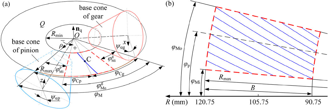
Figure 1. Schematic diagram of involute tooth surface meshing: (a) basic illustration of meshing principles in bevel gear; (b) sector area of contact. Curves in blue are the calculation result of the contact line by Equation 3; the sector area in (b) in the red dotted line is composed of the endpoints of the contact lines.
—where R is the cone distance,
To clarify the relationship between planar and spherical involute surfaces, a mathematical derivation is included in Appendix A to show that the planar involute can be obtained as a limiting case of the spherical involute when the base cone angle approaches zero. Although this study focused on bevel gears with spherical involute surfaces, the analytical framework remains closely related to that of cylindrical gears. The geometric and contact properties of planar involute tooth surfaces can thus be regarded as the projection of spherical involute curves defined on a common cone distance extended along the generatrix direction. Therefore, spherical involute models provide a generalized analytical basis applicable to both bevel and spur gear analysis.
Our research centers on a spherical involute gear pair utilized in textile machines in a dobby system. The curved tooth along the cone distance is described by the tooth trace line f, which is defined as the angle around the axis of two points with different cone distances on the tooth line. It is a conical helix expressed in Equation 2 in the studied gear drive.
—where the spiral angle
The contact area on a tooth surface moves from the meshing-in point to the meshing-out point while the tooth surface itself rotates around the axis of rotation. The involute surfaces contact at the tangent plane, and their contact line can be obtained from the intersection of one of the two tooth surfaces with the tangent plane Q (Zhang et al., 2023). The calculation formula within the coordinate system Oρφ is depicted as Equation 3, derived from Equation 1 (Table 1)
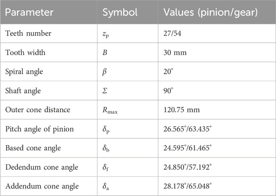
Table 1. Parameters of spherical involute.
—where the function
The contact ratio refers to the proportion of the total contact area between the meshing teeth of two gears within a specific time or angular range. This parameter indicates the stability and smoothness of meshing and is crucial for determining the meshing performance and design of a gear system. In addition to the transverse contact ratio, involute gears also possess an additional overlap contact ratio because their teeth are curved along the axis of rotation. εα = 1.520,929 and εβ = 1.062988 are calculated according to the gear pair listed in Table 1. The contact ratio of the studied involute gear pairs ε = 2.583,917 is thus obtained.
3 Analysis of contact characteristics
The friction and compression between the tooth surfaces during the meshing lead to the release of energy, resulting in a sudden temperature rise that persists in the meshing process. The flash temperature is related to the contact characteristics and relative velocity between the tooth pair.
3.1 Tangential velocity of the contact area
The relative tangential velocity between two gears is defined as the speed difference at which the contact area moves across their respective tooth surfaces. This motion of the contact area can be conceptually understood as the progression of points along the involute direction on the tooth surface. The mathematical representation for the arc length of a spherical involute between two adjacent points is given by Equation 5.
—where
—where Δt is the time elapsed during the transition of the contact area to the adjacent point. The results obtained by Equation 6 according to the parameters in Table 1 are illustrated in Figure 2 as the rotating speed of the pinion n = 1200r/min.
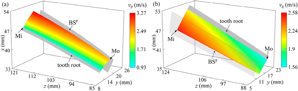
Figure 2. Velocity of the contact area (a) on the tooth surface of the pinion and (b) on the tooth surface of the gear, where Mi and Mo represent mesh-in and mesh-out, respectively.
The contact area on the tooth surface moves at a faster rate as the cone distance, cone angle, and angular displacement of the involute increase (Equation 5). It is shown in Figure 2 that the minimum value occurs at the lower inner corner of the tooth surface. As the cone distance and tooth height increase, the value rises and reaches its peak at the upper outer end. The two calculation results from the tooth surfaces of the pinion and gear are entirely contained within each other, demonstrating symmetry around their respective midpoints. The tangential velocity range for the contact area on the pinion tooth surface is (0.939,805 m/s, 3.267457 m/s), which is larger than that on the gear (1.562,401 m/s, 2.076734 m/s) due to differences in angular velocity determined by the transmission ratio.
The relative tangential velocity shown in Equation 7 is obtained from the differences in the velocity of the contact area on the two surfaces:
Their results obtained according to the parameters in Table 1 are illustrated in Figure 3. The relative velocity is zero at the pitch circle. It then progressively rises from the pitch circle toward both the tooth tip and root. The peak value of 1.33 m/s marked by the red area increases as the cone distance rises.
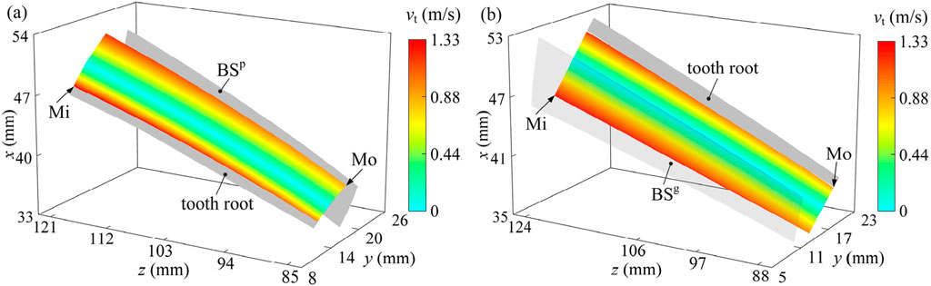
Figure 3. Relative tangential velocity of the tooth pair in involute gear: (a) displayed on the tooth surface of the pinion; (b) displayed on the tooth surface of the gear. Mi and Mo are the mesh-in and mesh-out positions, respectively.
Principal curvatures play a key role in defining the contact profile as they determine how surfaces interact. To clearly show the effect of gear displacement on the surface gap, a theoretical spherical involute tooth surface in Table 1 is used for analysis. It ensures a zero-distance area between meshing surfaces and covers the entire tooth surface throughout the meshing process.
Figure 4a shows the principal curvature κ1 of the pinion, where the values range more dramatically from 34.80 (1/m) near the toe to 121.4 (1/m) near the top. Similarly in Figure 4b, κ1 of the gear ranges from 13.20 (1/m) near the toe and root to 21.8 (1/m) near the top and heel, demonstrating an increase in curvature as the position moves toward the top of the tooth surface.
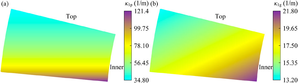
Figure 4. Principal curvatures of the spherical involute tooth surface: (a) curvatures of the pinion along the tooth height direction; (b) curvatures of the gear along the tooth height direction.
This significant disparity in curvature between the toe and top regions highlights a sharper geometry in the root region of the gear, suggesting higher stress concentrations and the potential for greater localized wear. Such non-uniform curvature distributions indicate the need for targeted optimization, especially in the vicinity of these extremities. The difference in principal curvature between the two tooth surfaces along the tooth height direction leads to a reduction in the contact area width in this direction.
3.2 Analysis of flash temperature
The flash temperature of the tooth surface can be determined using Equation 9, which is based on Blok’s flash temperature theory (Blok, 1963):
—where u = 0.83 is the temperature rise coefficient,
The flash temperature on a tooth surface in a full meshing cycle is visually represented in Figure 5. The results are based on Equation 9 and the parameters in Table 1, with an output torque of Tg = 500 Nm and the pinion rotating at n = 500 r/min.
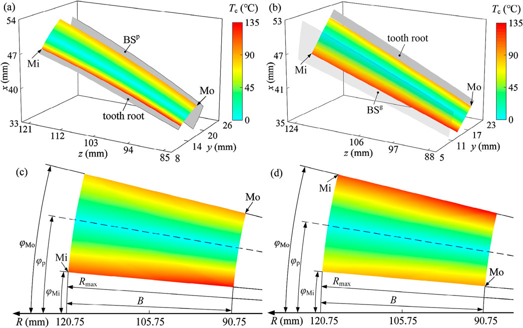
Figure 5. Flash temperature of the tooth surface in involute gear: (a) on the tooth surface of the pinion; (b) on the tooth surface of the gear; (c) on the plane Q of the pinion; (d) on the plane Q of the gear. Mi and Mo are respectively the mesh-in and mesh-out positions, the dotted line --- in (c,d) represents the pitch circle, and parameter R in (c,d) is the cone distance.
The flash temperature initiates at zero along the pitch circle and gradually increases toward both the tooth tip and root. The rate of increase is correlated with the radians from the pitch circle. This indicates that the contact is not influenced by the cone distance, unlike the relative tangential velocity of the tooth surface. The observed temperature distribution closely follows the pattern of the relative tangential velocity, indicating a strong correlation with frictional heat generation. Crucially, the temperature remains remarkably uniform along the tooth width direction, showing no significant variation from the inner to the outer end. Contrary to what might be expected from the velocity profile, the temperature at the outer end is not markedly higher than at the inner end. The peak temperatures are localized within specific engagement zones, such as near the tooth root.
The contact area moves through positions Mi to Mo on the tooth surface and acts as a series of contact lines, synchronizing with the occurrence of flash temperature. The maximum flash temperature along a contact line, along with its corresponding position, is calculated and illustrated in Figures 6a, b, respectively. The flash temperature varies along a contact line, with its highest and lowest points occurring at the respective ends unless the contact line intersects with the pitch circle. Its average value closely aligns with the value at the midpoint of the contact line. This difference widens with the length of the contact line. Figure 6a shows that the maximum value is almost all at the upper and lower boundaries of the meshing area on the tooth surface.
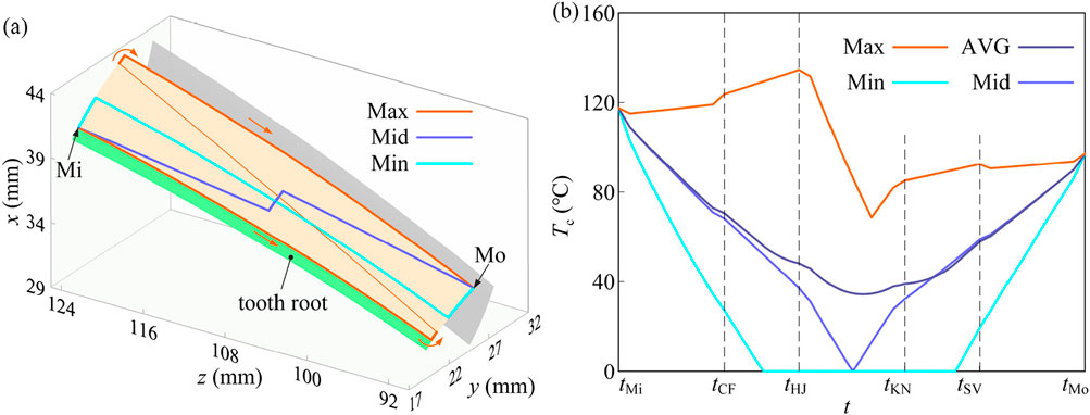
Figure 6. Distribution law of flash temperature along the contact line in involute gear: (a) track of special points displayed on the tooth surface; (b) value analysis. Mi and Mo are the mesh-in and mesh-out positions, respectively.
4 Tooth deflection and gear meshing stiffness
Meshing stiffness is an important time-varying parameter of the involute gear pair which changes with the spatial position of the meshing point along the action line. It is generally considered to be composed of Hertz contact stiffness kh, fillet-foundation stiffness kf, bending stiffness kb, shear stiffness ks, and axial compression stiffness ka. The calculation model of time-varying meshing stiffness (TVMS) is established and illustrated on the Q plane in this section based on the potential energy method.
4.1 Calculation of tooth stiffness
Hertzian contact stiffness kh characterizes the local elastic response at the contact interface. While for spur gears the contact geometry allows kh to be treated as approximately constant, the situation is fundamentally different in bevel gears with curved tooth surfaces. The effective contact area is confined along the tooth height direction due to the narrow contact width, making the contact length (along the tooth width) a primary geometric descriptor of the contact area. Under small-deformation assumptions, kh is inherently related to the contact area, which in turn is governed by the accessible contact length. This relationship has been analytically demonstrated by Zhang and Xu. (2025), where the correlation between the contact area and stiffness is explicitly derived. Hence, kh in bevel gears varies with contact position due to spatial variation of contact geometry and is primarily dictated by the evolving effective contact area across the meshing cycle. Hence, kh in bevel gears varies with contact position due to the spatial variation of contact geometry and can be quantitatively evaluated using the Hertzian formulation kh = πE∗l/2, where E∗ is the equivalent elastic modulus and l is the effective contact length.
The potential energy method is widely used for calculating the meshing stiffness of spur and helical gears. This method can also be adapted for use in analyzing involute gears wherein they are simplified into a series of sliced straight bevel gears along the tooth width direction. The normal force
—where v is Poisson’s ratio,
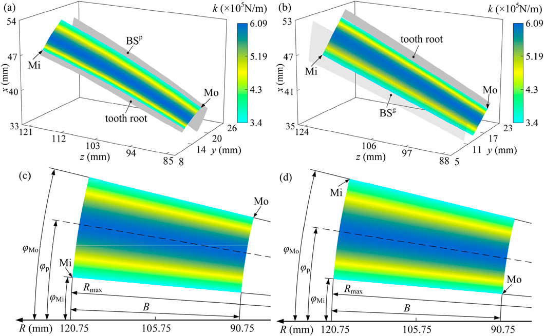
Figure 7. Tooth stiffness of involute gear: (a) on the tooth surface of the pinion; (b) on the tooth surface of the gear; (c) on the plane Q of the pinion; (d) on the plane Q of the gear. Mi and Mo are the mesh-in and mesh-out positions, respectively, the dotted line --- in (c,d) represents the pitch circle, and parameter R in (c,d) and (d) is the cone distance.
It can be seen from the figure that the tooth stiffness gradually increases. This will increase to the maximum values first and then decrease when the contact remains constant as
Analysis of the mesh stiffness distribution (Figure 7) reveals that the highest values (approximately 5.19 × 10⁵ N/m to 6.09 × 10⁵ N/m) are concentrated in a central band aligned with the pitch line and extending across the mid-face width region of the tooth flank. Stiffness progressively decreases with increasing distance from this central high-stiffness zone. Intermediate values (approximately 4.3 × 10⁵ N/m to 5.19 × 10⁵ N/m) are found in areas transitioning toward the tooth profile extremities and near the edges of the face width. The minimum stiffness values (approximately 3.4 × 10⁵ N/m to 4.3 × 10⁵ N/m) consistently occur at the tooth root fillet region and the tooth tip. This pattern arises due to the combined effects of the thickest effective material cross-section near the pitch line, susceptibility to bending deflection at the root, and localized edge contact conditions at the tip, with the steepest decrease observed toward the root.
4.2 Deflection of the tooth pair
Tooth deflection occurs as a result of the deformation in the gear foundation structure. The tooth is supposed to be rigid, and the gear foundation structure is modeled as an elastic half-plane for calculating fillet-foundation stiffness. The position change of a tooth caused by the meshing forces acting on its neighboring teeth is ignored here. An analytical formula proposed by Sainsot and et al. (2004) is expressed as Equation 11 for calculating the tooth deflection caused by the meshing force acting upon it.
—where sf and h are the tooth thickness at the critical section of the dedendum circle and the tooth height at the meshing point, respectively, and the coefficients L1, M1, P1, and Q1 are constants for a given mesh point. More details about the variables in Equation 10 can be found in Sainsot et al. (2004). The tooth deflection can be determined by combining the deflection caused by the meshing forces (Figure 8). This relationship can be mathematically expressed as Equation 12 in conjunction with the fillet-foundation stiffness.
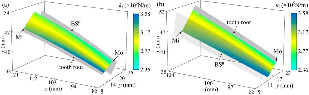
Figure 8. Fillet-foundation stiffness of involute gear: (a) on the tooth surface of the pinion; (b) on the tooth surface of the gear. Mi and Mo are the mesh-in and mesh-out positions, respectively.
Tooth deflection is depicted as a rotational movement along the axis due to the varying radii of meshing forces along the contact line. The deformation and deflection of a tooth pair will not significantly change in a certain working condition because the meshing stiffness of the tooth pair follows the trends of the load distribution ratio. Based on the analysis of the fillet-foundation stiffness (kf, ×105 N/m) distribution on the pinion (Figure 8a) and gear (Figure 8b) tooth surfaces, a distinct pattern emerges characterized by the highest values concentrated within the central region of the tooth root area and decreasing toward the periphery. Specifically, the maximum fillet-foundation stiffness values (approximately 3.58 × 10⁵ N/m) are consistently located near the middle of the face width (y-direction) and within the tooth root region (z = 121 mm for pinion, z = 124 mm for gear), as indicated by the deep blue contours near labels “tooth root/BSP” and “tooth root/BSg”. Stiffness progressively decreases with increasing distance from this central root zone. Intermediate values (approximately 2.77–3.17 × 10⁵ N/m) are observed moving toward the edges of the face width and also extending slightly toward the pitch line direction (z decreasing toward 94 mm for pinion, 97/106 mm for gear). The minimum fillet-foundation stiffness values (approximately 2.36 × 10⁵ N/m, shown in light yellow/green) consistently occur at the extremities of the analyzed root region, particularly toward the outer edges of the face width and the area bordering the active flank closer to the pitch line. This distribution pattern highlights that the foundation beneath the tooth root is most resistant to deflection centrally within the root zone across the face width, with reduced support stiffness toward the gear body edges and the transition towards the meshing flank.
4.3 Calculation model of TVMS
The meshing stiffness of a meshing point on the jth tooth pair and the meshing stiffness of a tooth pair in the involute gear kj can be integrally written as Equation 13 according to the elastic potential energy principle.
The meshing stiffness of a tooth pair involute gear and its five adjacent tooth pairs in a full meshing period (Figure 9) can be obtained by Equation 13 according to the parameters in Table 1.
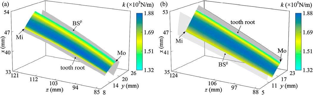
Figure 9. Single tooth stiffness in involute gear: (a) on the tooth surface of the pinion; (b) on the tooth surface of the gear. Mi and Mo are the mesh-in and mesh-out position, respectively.
The meshing stiffness of a tooth pair increases with the size of the contact area and reaches its maximum value in the second three-tooth pair meshing region.
The contact ratio of the analyzed involute gear pair is determined to be 2.583,917. This indicates that two or three pairs of teeth are simultaneously engaged in meshing. The meshing stiffness of all tooth pairs is shown in Figure 10. The meshing stiffness is the superposition of the stiffness contributions from all tooth pairs simultaneously engaged in contact. The number of engaged teeth varies between two adjacent integers of the contact ratio and the contact positions on each tooth surface differ at any given moment. When the contact ratio falls between 2 and 3, the meshing process transitions through alternating phases of triple- and double-tooth engagement. Accordingly, the tooth surface is divided into triple- and double-tooth contact regions (Figures 10a and b, respectively). The overall meshing stiffness is obtained by summing the stiffness contributions over the active contact region, where the contact location shifts progressively from the Mi (meshing-in) end to the Mo (meshing-out) end.
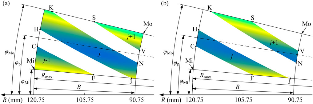
Figure 10. Meshing stiffness of involute gear pair: (a) three-pair teeth meshing; (b) double-pair teeth meshing. Mi and Mo are the mesh-in and mesh-out position, respectively, the dotted line --- is the pitch circle, and parameter R represents the cone distance.
4.4 Correlation analysis of stiffness, deflection, and thermal fields
The spatial distributions of tooth stiffness and flash temperature exhibit a strong resemblance. Both parameters remain nearly invariant along the face width direction and display symmetrical profiles with respect to the pitch circle along the tooth height. This symmetry indicates that cone distance has minimal influence on these two parameters, whereas tooth height plays a dominant role. Moreover, the relative tangential velocity and local tooth stiffness exhibit similar spatial behavior: both increase with distance from the pitch circle and are predominantly governed by the angular displacement and local curvature of the involute surface.
The fillet-foundation stiffness (Figure 8) shows a spatial distribution that aligns more closely with the velocity distribution on the tooth surface and the curvature of the spherical involute. This indicates a stronger dependence on cone distance and radial positioning than observed in contact stiffness alone. Such coupling arises because both curvature and local motion trajectories influence the contact pressure footprint and structural compliance of the tooth root region. Although the TVMS is composed of multiple stiffness components—including bending, shear, axial compression, contact, and foundation stiffness—its overall variation is largely governed by the spatial distribution of local tooth stiffness. Consequently, the TVMS contour maps demonstrate a distribution pattern similar to that of contact stiffness and flash temperature, with maximum values near the pitch circle and minima toward the tooth root and tip. This co-evolution of thermal and mechanical parameters provides insight into the coupled thermo-mechanical behavior of bevel gears and offers guidance for localized surface modifications aimed at reducing peak stresses and thermal loads.
5 Conclusion
This study presents an application-driven spatial analysis of contact deformation, meshing stiffness, and flash temperature in involute gear pairs. While the methods used are based on classical formulations, the value of the work lies in providing a complete spatial mapping of contact-related quantities across the tooth surface. This distributional information serves as a practical reference for gear designers, especially in cases where only partial contact occurs and contact path design is based on intuition or oversimplified criteria. By identifying characteristic trends and sensitivities along the tooth width and height directions, the results contribute to a more quantitative understanding of localized contact behavior.
Tangential velocity, a key factor that influences flash temperature, increases with tooth height and cone distance on both driving and driven gear surfaces, reaching its maximum at the tooth tip on the outer end. The relative tangential velocity between the two mating surfaces increases from the pitch circle toward both the root and tip and shows a mild increase with cone distance. This trend mirrors the flash temperature distribution: the highest values persistently appear at the tooth root and tip, while the minimum is observed near the pitch circle. Edge regions, particularly on the inner end, exhibit elevated flash temperatures.
Contact stiffness exhibits symmetry along the tooth-height direction. It peaks near the pitch circle, corresponding to regions of minimal flash temperature and tangential sliding. Although variations in meshing stiffness across the surface are less pronounced, it generally decreases at the root and tip, with the inner end exhibiting lower stiffness than the outer end. Regions near the outer end are more favorable for contact due to their relatively lower flash temperature and higher stiffness. High flash temperature and low contact stiffness at the tooth tip and inner end suggest the need for profile modifications, particularly tip relief, to suppress excessive flash temperature and improve load capacity. These findings provide a quantitative basis for optimizing contact paths and modifying surface geometry in gear design.
Data availability statement
The original contributions presented in the study are included in the article/supplementary material; further inquiries can be directed to the corresponding author.
Author contributions
HD: Resources, Funding acquisition, Project administration, Formal analysis, Supervision, Conceptualization, Writing – original draft, Data curation. YZ: Investigation, Visualization, Software, Writing – review and editing, Conceptualization, Validation, Data curation, Methodology, Writing – original draft. LX: Supervision, Project administration, Funding acquisition, Writing – review and editing.
Funding
The author(s) declare that financial support was received for the research and/or publication of this article. This research is sponsored by the Aeronautical Science Foundation of China (Grant No. 202300020Q9009) and the Fundamental Research Funds for the Central Universities (Grant No. 2024CDJGF-040).
Conflict of interest
The authors declare that the research was conducted in the absence of any commercial or financial relationships that could be construed as a potential conflict of interest.
Generative AI statement
The author(s) declare that no Generative AI was used in the creation of this manuscript.
Publisher’s note
All claims expressed in this article are solely those of the authors and do not necessarily represent those of their affiliated organizations, or those of the publisher, the editors and the reviewers. Any product that may be evaluated in this article, or claim that may be made by its manufacturer, is not guaranteed or endorsed by the publisher.
Abbreviations
B, β, Σ, tooth width, spiral angle, shaft angle; E, G, v, modulus of elasticity, transverse modulus of elasticity, Poisson’s ratio; Fm, FN,i (i = 1,2,···, nj), meshing force, normal forces acting on teeth along the contact line; Fa, Fr, Ft, axial force, radial force, tangential force; I, A, moment of inertia, area of the section; L, load distribution ratio; Q, common tangent plane of base cones; R, Rmax, Rmin, cone distance, outer cone distance, inner cone distance; T, temperature; h, s, tooth height, tooth thickness; lj, lm, length of contact line on the jth tooth, total length of the contact line; kt, kb, ks, ka, kh, kf, stiffness, bending, shear, axial compression, contact, and fillet-foundation stiffness; v, vt, tangential velocity, relative velocity between contact area on tooth pair; n, normal vector; zp, zg, number of teeth on the pinion and gear, respectively; ΔR, Δs, tooth width of the current element and its contact line; δf, δh, fillet-foundation deflection, contact deformation; εm, εα, εβ, contact ratio, transverse contact ratio, overlap contact ratio; θp, θg, rotation angle of the pinion and gear as they mesh in, respectively; τ, 1, τ2, tangent vector of spherical involute and contact line, respectively; φb, φp, φf, φa, involute angle corresponding to base, reference, dedendum, and addendum angle; ψ, ψb, rotation angle of the base cone, parameter for the tooth trace line function f (·); ωp, ωg, angular velocity of pinion and gear, respectively; Mi, Mo, mesh-in, mesh-out; i = 1, 2,···, nj, order of the meshing forces and tooth slices; j = 1, 2, 3,···, z, jth tooth pair; m = 2, 3, n = 1,···, m, codes of different meshing regions; o = p, g, pinion (o = p) and gear (o = g).
References
Álvarez, Á., Calleja, A., Ortega, N., and De Lacalle, L. (2018). Five-axis milling of large spiral bevel gears: toolpath definition, finishing, and shape errors. Metals 8 (5), 353. doi:10.3390/met8050353
Barone, S., Borgianni, L., and Forte, P. (2004). Evaluation of the effect of misalignment and profile modification in face gear drive by a finite element meshing simulation. J. Mech. Des. 126 (5), 916–924. doi:10.1115/1.1767818
Blok, H. (1963). The flash temperature concept. Wear 6 (6), 483–494. doi:10.1016/0043-1648(63)90283-7
Bo, P., González, H., Calleja, A., de Lacalle, L. N. L., and Bartoň, M. (2020). 5-axis double-flank CNC machining of spiral bevel gears via custom-shaped milling tools—Part I: modeling and simulation. Precis. Eng. 62, 204–212. doi:10.1016/j.precisioneng.2019.11.015
Bracci, A., Gabiccini, M., Artoni, A., and Guiggiani, M. (2009). Geometric contact pattern estimation for gear drives. Comput. methods Appl. Mech. Eng. 198 (17-20), 1563–1571. doi:10.1016/j.cma.2009.01.009
Chao, L. C., and Tsay, C. B. (2008). Contact characteristics of spherical gears. Mech. Mach. Theory 43 (10), 1317–1331. doi:10.1016/j.mechmachtheory.2007.10.008
Chen, S., Wei, J., Wei, H., Tan, Y., Ye, J., Liu, C., et al. (2025). Integrated design-optimization method for high-performance and lightweight spiral bevel gears. Int. J. Mech. Sci. 296, 110348. doi:10.1016/j.ijmecsci.2025.110348
Cheng, G., Xiao, K., and Wang, J. (2021). Contact damping and stiffness calculation model for rough surface considering lubrication in involute spur gear. Int. J. Appl. Mech. 13 (07), 2150078. doi:10.1142/s1758825121500782
Chin, Z. Y., Borghesani, P., Smith, W. A., Randall, R. B., and Peng, Z. (2023). Monitoring gear wear with transmission error. Wear 523, 204803. doi:10.1016/j.wear.2023.204803
Cooley, C. G., Liu, C., Dai, X., and Parker, R. G. (2016). Gear tooth mesh stiffness: a comparison of calculation approaches. Mech. Mach. theory 105, 540–553. doi:10.1016/j.mechmachtheory.2016.07.021
Ding, H., Zhou, Y., Tang, J., Zhong, J., Zhou, Z., and Wan, G. (2017). A novel operation approach to determine initial contact point for tooth contact analysis with errors of spiral bevel and hypoid gears. Mech. Mach. Theory 109, 155–170. doi:10.1016/j.mechmachtheory.2016.11.007
Escudero, G. G., Bo, P., González-Barrio, H., Calleja-Ochoa, A., Bartoň, M., and de Lacalle, L. N. L. (2022). 5-axis double-flank CNC machining of spiral bevel gears via custom-shaped tools—Part II: physical validations and experiments. Int. J. Adv. Manuf. Technol. 119 (3), 1647–1658. doi:10.1007/s00170-021-08166-0
Hu, Z., Ding, H., Peng, S., Tang, Y., and Tang, J. (2018). Numerical determination to loaded tooth contact performances in consideration of misalignment for the spiral bevel gears. Int. J. Mech. Sci. 11, 343–355. doi:10.1016/j.ijmecsci.2018.11.014
Hu, Z., and Mao, K. (2017). An investigation of misalignment effects on the performance of acetal gears. Tribol. Int. 116, 394–402. doi:10.1016/j.triboint.2017.07.029
Jiang, C., and Liang, X. (2024). An incremental contact model for hyperelastic solids with rough surfaces. Tribol. Lett. 72 (1), 1. doi:10.1007/s11249-023-01800-w
Jurkiewicz, A., Pawlikowski, M., and Pyryev, Y. (2017). Analytical, numerical and experimental analysis of the relationship between two rollers axes distance and the contact zone. Int. J. Mech. Sci. 131, 722–727. doi:10.1016/j.ijmecsci.2017.07.030
Karpat, F., Ekwaro-Osire, S., Cavdar, K., and Babalik, F. C. (2008). Dynamic analysis of involute spur gears with asymmetric teeth. Int. J. Mech. Sci. 50 (12), 1598–1610. doi:10.1016/j.ijmecsci.2008.10.004
Kleemola, J., and Lehtovaara, A. (2009). Experimental simulation of gear contact along the line of action. Tribol. Int. 42 (10), 1453–1459. doi:10.1016/j.triboint.2009.06.007
Kumar, P., Hirani, H., and Agrawal, A. K. (2019). Effect of gear misalignment on contact area: theoretical and experimental studies. Measurement 132, 359–368. doi:10.1016/j.measurement.2018.09.070
Li, X., Tang, J., Shao, W., Zhang, D., Chen, J., Zhao, J., et al. (2024). Gear contact fatigue prediction under mixed elastohydrodynamic lubrication with ellipsoidal asperity rough surface: experimental and numerical investigation. Eng. Fract. Mech. 307, 110334. doi:10.1016/j.engfracmech.2024.110334
Li, Z., Zhu, L., Chen, S., Chen, Z. G., and Gou, X. F. (2022). Study on safety characteristics of the spur gear pair considering time-varying backlash in the established multi-level safety domains. Nonlinear Dyn. 109 (3), 1297–1324. doi:10.1007/s11071-022-07467-7
Lin, C. H., and Fong, Z. H. (2015). Numerical tooth contact analysis of a bevel gear set by using measured tooth geometry data. Mech. Mach. Theory 84, 1–24. doi:10.1016/j.mechmachtheory.2014.09.010
Mao, K. (2007). Gear tooth contact analysis and its application in the reduction of fatigue wear. Wear 262 (11-12), 1281–1288. doi:10.1016/j.wear.2006.06.019
Marafona, J. D. M., Marques, P. M. T., Martins, R. C., and Seabra, J. H. (2021). Mesh stiffness models for cylindrical gears: a detailed review. Mech. Mach. Theory 166, 104472. doi:10.1016/j.mechmachtheory.2021.104472
Munro, R. G., Morrish, L., and Palmer, D. (1999). Gear transmission error outside the normal path of contact due to corner and top contact. Proc. Institution Mech. Eng. Part C J. Mech. Eng. Sci. 213 (4), 389–400. doi:10.1243/0954406991522347
Natali, C., Battarra, M., Dalpiaz, G., and Mucchi, E. (2021). A critical review on FE-based methods for mesh stiffness estimation in spur gears. Mech. Mach. Theory 161, 104319. doi:10.1016/j.mechmachtheory.2021.104319
Sainsot And, P., Velex, P., and Duverger, O. (2004). Contribution of gear body to tooth Deflections—a new bidimensional analytical formula, 126-4, 748–752.
Sanchez-Marin, F., Iserte, J. L., and Roda-Casanova, V. (2016). Numerical tooth contact analysis of gear transmissions through the discretization and adaptive refinement of the contact surfaces. Mech. Mach. Theory 101, 75–94. doi:10.1016/j.mechmachtheory.2016.03.009
Sauer, R. A., and De Lorenzis, L. (2013). A computational contact formulation based on surface potentials. Comput. Methods Appl. Mech. Eng. 253, 369–395. doi:10.1016/j.cma.2012.09.002
Shi, J., Gou, X., and Zhu, L. (2019). Modeling and analysis of a spur gear pair considering multi-state mesh with time-varying parameters and backlash. Mech. Mach. Theory 134, 582–603. doi:10.1016/j.mechmachtheory.2019.01.018
Suh, S. H., Lee, E. S., Kim, H. C., and Cho, J. (2002). Geometric error measurement of spiral bevel gears using a virtual gear model for STEP-NC. Int. J. Mach. Tools Manuf. 42 (3), 335–342. doi:10.1016/s0890-6955(01)00130-4
Vivet, M., Mundo, D., Tamarozzi, T., and Desmet, W. (2018). An analytical model for accurate and numerically efficient tooth contact analysis under load, applied to face-milled spiral bevel gears. Mech. Mach. Theory 130, 137–156. doi:10.1016/j.mechmachtheory.2018.08.016
Wang, Z., Pu, W., Pei, X., and Cao, W. (2022). Contact stiffness and damping of spiral bevel gears under transient mixed lubrication conditions. Friction 10, 545–559. doi:10.1007/s40544-020-0479-8
Wriggers, P. (1995). Finite element algorithms for contact problems. Archives Comput. methods Eng. 2, 1–49. doi:10.1007/bf02736195
Wu, J., Wei, P., Liu, G., Chen, D., Zhang, X., Chen, T., et al. (2024). A comprehensive evaluation of DLC coating on gear bending fatigue, contact fatigue, and scuffing performance. Wear 536, 205177. doi:10.1016/j.wear.2023.205177
Yang, D. C. H., and Lin, J. Y. (1987). Hertzian damping, tooth friction and bending elasticity in gear impact dynamics. ASME. J. Mech. Des. 109 (2), 189–196. doi:10.1115/1.3267437
Yang, D. C. H., and Sun, Z. S. (1985). A rotary model for spur gear dynamics. ASME. J. Mech. Transm. Automation Des. 107 (4), 529–535. doi:10.1115/1.3260759
Zhang, Y., and Xu, L. (2025). Curvature-based framework for contact analysis of complex tooth surfaces. Int. J. Mech. Sci. 293, 110147. doi:10.1016/j.ijmecsci.2025.110147
Zhang, Y., Zhu, L., and Gou, X. (2023). Calculation methods of load distribution ratio for spiral bevel gear. Int. J. Mech. Sci. 257, 108531. doi:10.1016/j.ijmecsci.2023.108531
Zheng, F., Xin, S., Han, X., Hua, L., Zhuang, W., Hu, X., et al. (2024). Heavy-load nonapod: a novel flexible redundant parallel kinematic machine for multi-DoF forming process. Int. J. Mach. Tools Manuf. 200, 104183. doi:10.1016/j.ijmachtools.2024.104183
Zheng, X., Luo, W., Hu, Y., and Wang, S. (2022). Analytical approach to mesh stiffness modeling of high-speed spur gears. Int. J. Mech. Sci. 224, 107318. doi:10.1016/j.ijmecsci.2022.107318
Appendix A: Derivation of planar involute equation as a limiting case of the spherical involute
A base cone with apex at the origin, axis aligned with the z-axis, base cone angle δb, and cone distance R. When intersected by a plane z = (R–B)cosδb for a constant tooth width B, a truncated cone is formed. The radii of its two circular cross-sections are
As δb tends to zero and R tends to infinity while keeping rb constant, the cone degenerates into a cylinder of radius rb and height B. This establishes the geometric transition from a conical to a cylindrical shape. Denoting r = Rsinδb, φ = ψsinδb, the spherical involute in Equation 1 reduces to the parametric equations of the planar involute:
This limiting process also applies to other parameters such as pressure angle and profile shift, confirming that a cylindrical gear can be viewed as a limiting case of a bevel gear with an infinitesimally small cone angle and infinitely long generatrix. The derived relations are analytically exact.
Keywords: involute gear, contact deformation, mesh stiffness, flash temperature, spatial contact analysis
Citation: Dong H, Zhang Y and Xu L (2025) Spatial analysis of contact deformation, stiffness, and flash temperature in involute gear pairs. Front. Mech. Eng. 11:1643228. doi: 10.3389/fmech.2025.1643228
Received: 08 June 2025; Accepted: 14 July 2025;
Published: 04 August 2025.
Edited by:
Francesco Dal Corso, University of Trento, ItalyReviewed by:
Michael Leighton, Anstalt für Verbrennungskraftmaschinen List, AustriaYan Li, University of Shanghai for Science and Technology, China
Copyright © 2025 Dong, Zhang and Xu. This is an open-access article distributed under the terms of the Creative Commons Attribution License (CC BY). The use, distribution or reproduction in other forums is permitted, provided the original author(s) and the copyright owner(s) are credited and that the original publication in this journal is cited, in accordance with accepted academic practice. No use, distribution or reproduction is permitted which does not comply with these terms.
*Correspondence: Hongtao Dong, ZGh0NjA4QHNpbmEuY29t