 Yingya Huang
 Jieyu Tian*
- College of Railway Locomotive and Rolling Stock, Hebei Vocational College of Rail Transportation, Shijiazhuang, China
Introduction: This research focuses on optimizing the motion path of truss manipulators and proposes a path optimization method based on a simulated annealing algorithm and a neural network to address the positioning deviation problem that occurs in industrial production.
Methods: The research method first uses a simulated annealing algorithm to initially improve the path parameters and avoid falling into local optima. The path is then further optimized through a neural network to ensure the precision and energy productivity of the motion path.
Results: The experimental outcomes indicated that the proposed algorithm performs well across multiple indicators, reducing the path length to 12.486 m, improving energy consumption optimization by 23.78%, controlling the path error at 2.14 cm, and achieving a convergence speed of 147 iterations. Compared with other algorithms, the algorithm proposed in the study also has significant advantages in path smoothness and computation time.
Discussion: The significance of the research lies in providing an efficient and energy-saving optimization strategy for the motion path of truss manipulators in industrial automation, which is expected to improve production efficiency and reduce industrial energy consumption.
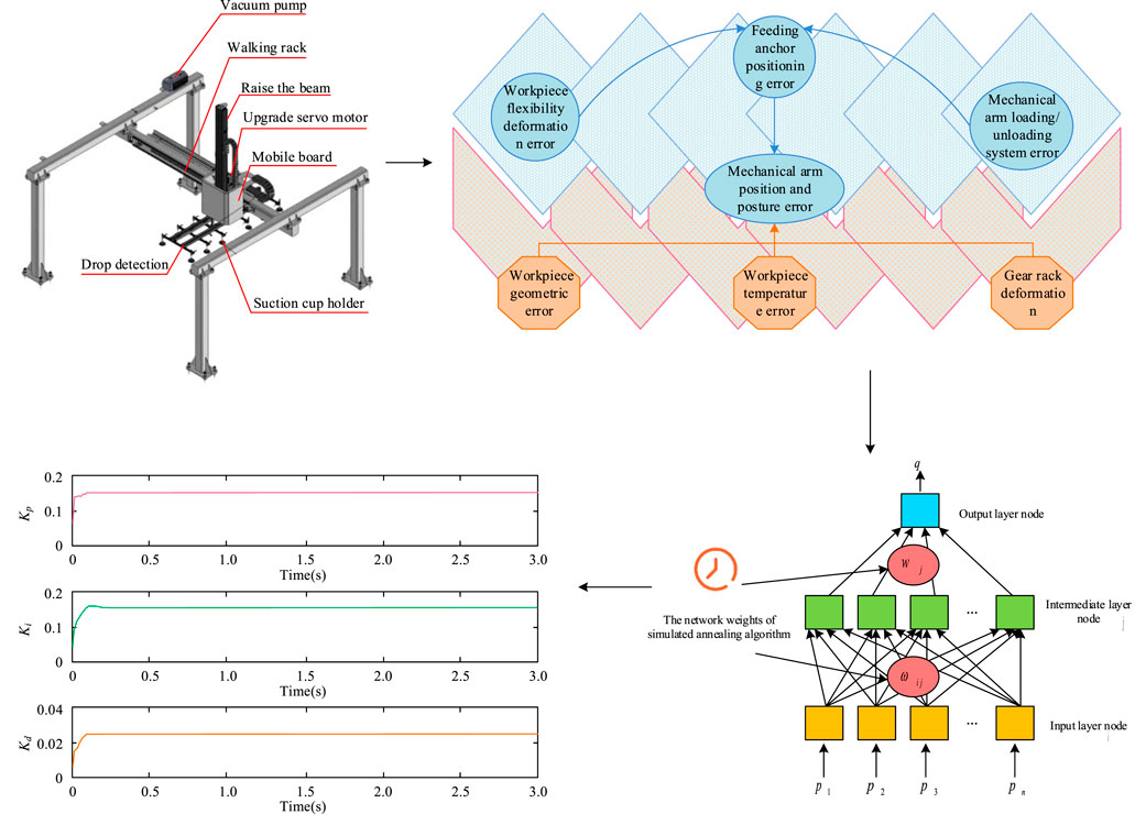
GRAPHICAL ABSTRACT | This research addresses significant geometric positioning errors in truss manipulator systems by proposing a hybrid optimization algorithm. The method uses a Simulated Annealing Algorithm (SAA) to initialize the weights of a Backpropagation (BP) neural network. The direct impact is a highly efficient control response, demonstrated by the rapid convergence of the system’s PID controller parameters (Kp, Ki, and Kd) to stable values within 0.2 s. This swift stabilization confirms the algorithm’s ability to produce a fast, stable, and accurately optimized motion path for the manipulator.
1 Introduction
With the thriving development of industrial automation, the application of truss manipulators in production processes is experiencing a continuous and extensive expansion. They can automatically complete operations such as material grabbing, handling, and placement, significantly improving production efficiency and accuracy (Zhou et al., 2024). However, in practical applications, because of the complicacy of the production status and the restrictive conditions of the robot arm’s own structure and control system, truss robots often face problems such as positioning errors and inaccurate path planning, which pose challenges to overall production efficiency and safety (Yaldız et al., 2013; Gök et al., 2017). Therefore, how to optimize the motion path of the truss manipulator to maintain high precision and stability in complex production environments has become a hot research topic (Aydın et al., 2015). Traditional path optimization methods for truss manipulators often rely on pre-set paths or simple algorithms for control, but these methods have significant limitations. Firstly, the pre-defined path encounters significant challenges in adapting to the dynamic alterations that may transpire throughout the production process. Moreover, once deviations emerge, the robotic arm exhibits limited capacity for self-adjustment (Han et al., 2023). Secondly, many existing optimization algorithms such as Genetic Algorithms (GA) and Particle Swarm Optimization (PSO) can optimize paths to a certain extent, but they tend to become trapped in local minima and cannot guarantee global optima (GO) (Liu B. et al., 2023). In addition, these algorithms have long computation times and low efficiency in complex path planning problems, making it difficult to meet the real-time and efficient requirements in industrial production. Therefore, traditional research still has many shortcomings in the accuracy, efficiency, and adaptability of path optimization.
Recent research has focused on using simulated annealing algorithms (SAA) and their combination with neural networks (NN) to optimize prediction and control problems for various complex systems. Yan et al. constructed the SA-GRU city flooding forecasting model based on Gated Recurrent Unit (GRU) NN and SAA to optimize hyperparameters. Compared to traditional models, SA-GRU had higher accuracy in short-term forecasting, effectively improving the accuracy and response speed of urban waterlogging warning (Yan et al., 2023). Tsoulos et al. proposed a novel combined way to improve the training efficiency of artificial NN in sorting learning and data fitting issues. This technology combined variants of GA and SAA, by periodically applying SAA to stochastically chosen chromosomes in the GA population to cut training errors related to these chromosomes (Tsoulos et al., 2024). The two-step SAA proposed by Pei et al. effectively improved the accuracy and stability of spectral feature extraction, which was consistent with the goal of studying and optimizing the path of truss manipulators, indicating the wide application of SAA in multiple fields and its ability to optimize complex systems (Pei et al., 2023). Rehman et al. used a two-step optimization algorithm based on Recurrent Neural Network (RNN) and improved the accuracy of wind speed data estimation by combining the Broyden-Fletcher-Goldfarb-Shanno algorithm with SA. The algorithm improved the accuracy and efficiency of path optimization for truss manipulators (Rehman et al., 2023). Yin et al. predicted the loss factor of particle dampers using SA backpropagation NN (SA-BP), which was consistent with the SA-BP method for optimizing the path of truss manipulators, demonstrating the effectiveness of SA-BP in complex engineering problems (Yin et al., 2023).
The efficiency of motion planning in the design of engineering systems such as truss robots has broad application prospects. Suvorov et al. used SA-BP NN to optimize the design of ship cranes, to cut weight and improve productivity. The optimization design method applied by it was consistent with the goal of studying the path optimization of truss manipulators, indicating the wide applicability of SA-BP algorithm in engineering optimization design (Suvorov et al., 2023). Cao et al. proposed a novel way for predicting the dependability of stamping machine loading and unloading truss robots. This method first used the component counting method to forecast the error rate of the electronic managing machinery, and then used the professional valuing strategy based on fuzzy theory to estimate the MTBF and error rate of the mechanical and pneumatic systems (Cao et al., 2024). Dai et al. used reinforcement learning and SA-BP algorithm to optimize the in orbit assembly of space trusses. Similar to the methods used in optimizing the path of truss manipulators, they combined multiple optimization strategies in complex systems to improve the efficiency of automation systems (Dai et al., 2023). A reinforcement learning algorithm proposed by Liu et al. optimized a variable topology truss robot and improved the assembly and motion planning efficiency of complex systems through intelligent optimization techniques (Liu C. et al., 2023). The improved sparrow algorithm designed by Dai et al. effectively planned the motion path of robots climbing trusses, improved the efficiency of path planning through optimization algorithms, and solved complex automation problems (Dai et al., 2024).
In summary, many experts have studied the application of NN-based path optimization and SAA in model training. However, current research still has shortcomings such as insufficient path planning accuracy, poor adaptability to dynamic environments, and long training time. Therefore, a research proposes a motion path optimization method for truss manipulators based on the combination of SA and BP NN to solve problems such as improving path accuracy, enhancing adaptability in dynamic environments, and improving training efficiency. The peculiar thing of the study lies in the SAA, which can effectively break out of local optima (LO) and explore GO solutions by simulating the state changes during the cooling process of materials. At the same time, combining BP NN to adaptively adjust path parameters further improves the accuracy and efficiency of path planning. The contribution of this research lies in proposing a hybrid SA-BP method which adeptly formulates a synergistic strategy combining ‘global exploration’ with ‘local exploitation’. Specifically, the SAA is employed to perform a global search to optimize the initial weights of the BP NN. This approach addresses the network’s tendency to settle in poor LO. Subsequently, the BP algorithm leverages its efficient local search capabilities to rapidly fine-tune the solution from this advantageous starting point. This integrated strategy is designed to enhance both the final accuracy and the computational efficiency of path optimization, providing a more intelligent and robust solution for truss manipulators in industrial automation.
2 Methods and materials
2.1 Optimization of motion path and automatic control strategy of truss robot arm
Truss manipulators are widely used in industrial automation, capable of automatically executing pre-programmed trajectories and actions to achieve operations such as grabbing and transporting objects. The key components include the actuator, drive system, control software, and sensing equipment, which together ensure the efficient material handling of the robotic arm in industrial production, as shown in Figure 1.
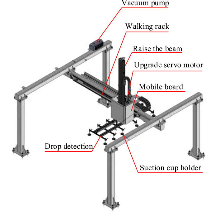
Figure 1. Truss manipulator.
As shown in Figure 1, the structure of the truss manipulator consists of a vacuum pump, a walking rack, an accumulator, a lifting beam, a lifting servo motor, a moving plate, a descent detection, and a suction cup frame. The vacuum pump is responsible for providing suction power, the walking rack guides the horizontal movement of the robotic arm, the accumulator maintains stable system pressure, and the lifting beam and lifting servo motor work together to achieve vertical movement of objects. The moving plate is used to carry and transport objects, the descent detection sensor monitors the descent process of objects, and the suction cup holder fixes the suction cup to grasp objects. Figure 2 shows the workflow of the truss manipulator.
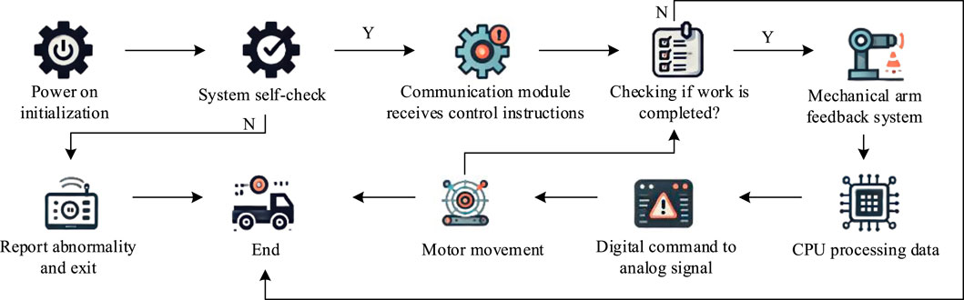
Figure 2. Workflow of the truss manipulator.
As shown in Figure 2, as the control center of the truss manipulator, the industrial controller is responsible for executing logical control tasks. It analyzes input signals, makes decisions based on the analysis results, and commands execution components. These components operate synchronously according to the instructions of the controller, achieving multi-axis coordinated actions of the robotic arm to complete automation tasks. Automated robotic arms are susceptible to environmental and equipment fluctuations during operation, resulting in workpiece positioning errors that can reduce efficiency and even cause machine tool collisions. Therefore, the machine tool system requires strict error control and coordination with other systems to adapt to complex production requirements. In the motion of the truss manipulator, significant positioning errors can occur, compromising precision and operational safety. These discrepancies primarily stem from geometric inaccuracies inherent in the mechanical system. Key contributing factors include manufacturing and assembly tolerances, rotational deviations in the gripper, wear and tear on components like gears and racks, and thermal expansion of the guide rails due to temperature changes. Figure 3 provides a schematic representation of these primary geometric errors within the manipulator’s coordinate system, illustrating how they contribute to the overall positioning deviation.
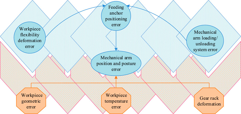
Figure 3. Geometric error of truss manipulator system.
In the motion of the truss manipulator, significant positioning errors can occur due to factors such as manufacturing, assembly, gripper rotation, gear and rack wear, and changes in guide rail temperature (Yaldız et al., 2016). To improve the positioning accuracy, an NN trained model combined with PID control algorithm is used for error compensation.
As shown in Figure 4, in the research of optimizing the motion path of the truss manipulator, it is necessary to first select a suitable factor encoding method to represent the motion path parameters of the manipulator. Subsequently, a path optimization objective function is constructed, which is used to evaluate the optimization process and guide the search direction. It adjusts weights through BP NN to further refine the motion path. Meanwhile, a comprehensive explanation of the weight optimization matter in the BP algorithm is provided to give a theoretical basis for the algorithm. During the SA process, the energy differences of different paths are calculated and annealing operations are performed to explore the solution space. The fitness of each solution is evaluated to determine its optimization potential. Ultimately, the initial solution is crafted to serve as the algorithm’s starting point, from which it iteratively seeks out the optimal path.
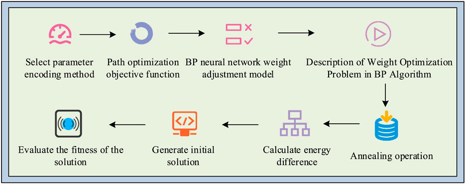
Figure 4. Optimization process of motion path for truss manipulator.
In this study, path smoothness is a critical metric used to evaluate the quality of the manipulator’s trajectory. It is quantified as the average cosine of the angle between consecutive path segments. For a path defined by a sequence of points
This metric yields a value between −1 and 1, where a value closer to one indicates a smoother path with minimal changes in direction. Path smoothness is highly relevant as it directly correlates with real-world performance. A smoother path reduces mechanical stress and vibrations on the manipulator’s joints and structure, leading to less wear and tear. Furthermore, it improves energy efficiency by minimizing abrupt accelerations and decelerations, and enhances stability when handling delicate or liquid materials (Kara et al., 2015).
2.2 Optimization of motion path for truss manipulator based on SA-BP algorithm and PID control
To optimize the motion path of the truss manipulator, research needs to be conducted according to the process shown in Figure 4. SAA is used for path planning of truss manipulator, mimicking the annealing process of material heating and gradually cooling. As an extension of the random search algorithm, it probabilistically accepts changes in the solution and adjusts the grope method over time to locate the overall best solution, decreasing the danger of falling into LO. The SAA model is shown in Figure 5.
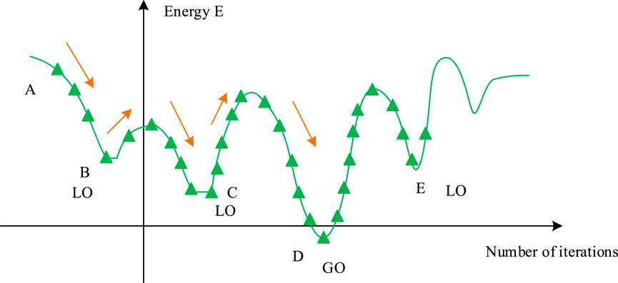
Figure 5. SAA model.
Figure 5 illustrates the core mechanism of the SAA, which is designed to find a GO solution by mimicking the physical process of annealing. The algorithm begins at an initial solution (State A) and explores the solution space by generating neighboring solutions (e.g., State B). The decision to move to a new state is governed by two principles. First, if the new solution is an improvement (i.e., has lower ‘energy’), it is always accepted, guiding the search towards better solutions. Second, and more critically, if the new solution is worse (higher ‘energy’), it may still be accepted based on a certain probability. This probabilistic acceptance allows the algorithm to make temporary ‘uphill’ moves, enabling it to escape LO that would trap simpler algorithms. As the algorithm progresses, a ‘temperature’ parameter is gradually lowered, which systematically reduces the probability of accepting worse solutions, ensuring that the search eventually converges towards the globally optimal state. The SAA combined with BP NN is represented in Figure 6.
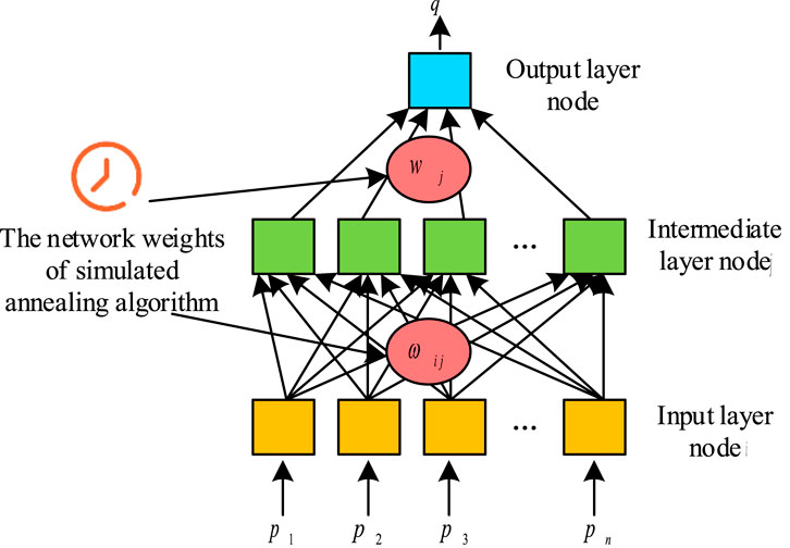
Figure 6. SAA combined with BP NN.
As represented in Figure 6, in the research on optimizing the motion path of the truss manipulator, SAA and BP NN are used to train the critical path parameters. Through a three-layer NN model, SAA is used to initialize network weights and avoid LO, while BP NN adjusts weights to optimize paths. The objective function evaluates the path efficiency to ensure that the robotic arm plans its motion path quickly and efficiently, improves production efficiency, and ensures operational safety (Agrawal et al., 2024). In this training model, the amount of input points is
In Formula 2,
In Formula 3,
In Formula 4,
In Formula 5,
In Formula 6,
In Formula 7,
In Formula 8,
In Formula 9,
Formula 10 is used to update the weights in the network to reduce the discrepancy between the forecasted result and the real target value. When studying the optimization of the motion path of the truss manipulator, the MPU6050 sensor is used to obtain real-time posture data of the manipulator, and the BP NN is applied to forecast the optimal motion trajectory. By combining SAA to optimize PID control parameters, the system can reduce actual motion deviation and ensure precise control.
In Formula 11,
In Formula 12,
In Formula 13,
The recursive formula for updating the weights of the third layer is shown in Formula 15.
In Formula 15,
In Formula 16,
3 Results
3.1 Performance evaluation and comparative analysis of SA-BP algorithm in optimizing the motion path of truss manipulator
The performance assessment metrics for the model were studied through three metrics: Mean Absolute Error (MAE), Root Mean Square Error (RMSE), and Mean Absolute Percentage Error (MAPE). The SA-BP algorithm was used to verify the optimization of the motion path of the truss manipulator. The network structure adopted a three-layer NN, with 10 IL nodes corresponding to multiple motion parameters of the truss manipulator. The amount of points in the hidden layer varied between 10 and 30. The OL was a single node that output the optimized motion path. The learning rate ranged from 0.0004 to 0.0012, and the gradient descent method was applied to optimize the model throughout the training phase. To determine the optimal hyper-parameters for the SA-BP model, a systematic tuning strategy based on Grid Search combined with 5-fold Cross-Validation was implemented. This approach ensured that the selected parameters were robust and not overfitted to a specific data split. The hyper-parameter space was defined based on preliminary experiments and common practices. Specifically, the number of hidden layer nodes was explored in the range of [10, 30] with an integer step of 2, while the learning rate was searched within the range of [0.0004, 0.0012] with a step of 0.0002. For each combination of hyper-parameters in the grid, the model was trained and evaluated using 5-fold cross-validation on the training dataset. The performance was measured by the average RMSE across the five validation folds. The combination yielding the lowest average RMSE was selected as the optimal configuration for the final model. The training data was the actual data of multiple motion paths of the robotic arm. This historical data were collected from a physical truss manipulator system as depicted in Figure 1. The data acquisition process involved executing a series of predefined motion tasks, such as pick-and-place operations, across various start and end points within the manipulator’s workspace. An MPU6050 inertial measurement unit was used to capture real-time posture data, including position, velocity, and acceleration for each axis. The dataset was structured as a time-series collection of data points, where each point contained a timestamp, the Cartesian coordinates (X, Y, Z) of the end-effector, its corresponding velocity and acceleration values, and the motor control signals sent from the controller. The error of SA-BP algorithm in optimizing the motion path of truss manipulator is shown in Figure 7.
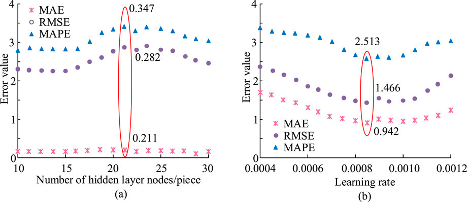
Figure 7. Error of SA-BP algorithm in optimizing the motion path of truss manipulator. (a) Number of nodes. (b) Number of Learning rate.
Figure 7a shows the trend of three indicators as the amount of hidden layer nodes rose from 10 to 30. When the amount of hidden layer points was 20, the MAE reached the lowest value of 0.211, while the RMSE and MAPE were 0.282 and 0.347, separately, indicating that the model performed best at this number of nodes. Figure 7b shows the variation of model error as the learning rate was adjusted from 0.0004 to 0.0012. When the learning rate was 0.0008, the error values of MAE, RMSE, and MAPE were 0.942, 1.466, and 2.513, separately. At this time, the model’s error was relatively lowest, indicating that the model performed best at this learning rate. To enhance the algorithm performance, a three-layer SA-BP NN model was applied in the validation experiment. The IL had 10 nodes representing the key motion parameters of the truss manipulator, the hidden layer has 20 nodes, and the OL output the optimized path for a single node. The model used mean square error (MSE) as the loss function, with a learning rate of 0.0008, and was optimized through gradient descent. The model was trained and tested using historical motion data, and its stability was ensured through cross validation. The loss convergence curves of the SA-BP algorithm training and testing sets are shown in Figure 8.
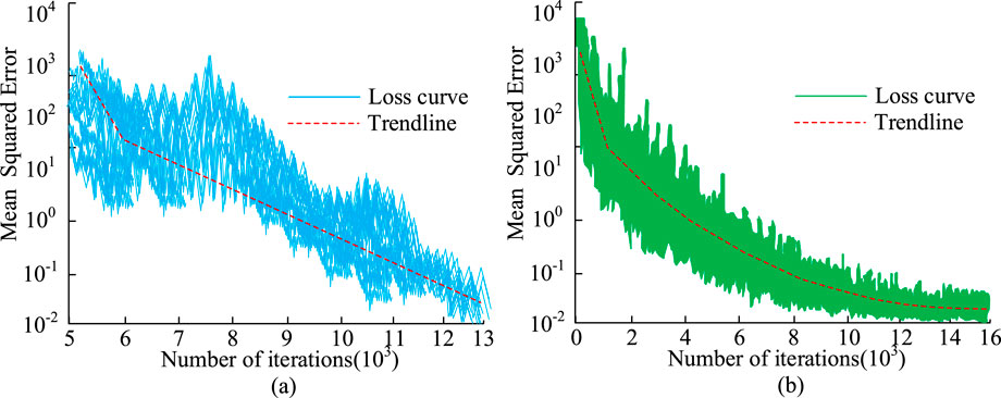
Figure 8. Loss convergence curves of SA-BP algorithm training and testing sets. (a) Training set loss rate. (b) Test set loss rate.
On the training set shown in Figure 8a, the mean square error rapidly decreases in the initial stage, then continues to steadily decrease and converges to nearly 10−2 around 1.3 × 10⁻⁴ iterations. Although there are slight fluctuations caused by random optimization, the overall trend is smooth and consistent; On the test set shown in Figure 8b, there is also monotonic convergence, with a rapid decline in the initial stage and a slow approach to the low error interval, reaching a low value of the same magnitude as the training set around 1.5-1.6 × 10⁻⁴ iterations. The continuous decline and convergence of the training and testing curves indicate that the model performs well in both optimization efficiency and generalization performance. It can quickly reduce errors without significant overfitting, thus demonstrating the advantages of the proposed method in terms of stability and prediction accuracy. To first evaluate the core discriminative power of the proposed model against other algorithms, a binary classification task was established as a preliminary assessment. In this framework, historical motion paths from the training dataset were labeled as either ‘acceptable’ (Class 1) or ‘unacceptable’ (Class 0) based on a predefined threshold of performance, such as exceeding a critical positioning error or failing to meet smoothness criteria. The performance of the SA-BP algorithm was benchmarked against four other common optimization algorithms (GA, PSO, DE, and ABC) on a binary classification task, with the results detailed in Table 1. This comparison aimed to assess the core discriminative power of each model in distinguishing between ‘acceptable’ and ‘unacceptable’ motion paths.
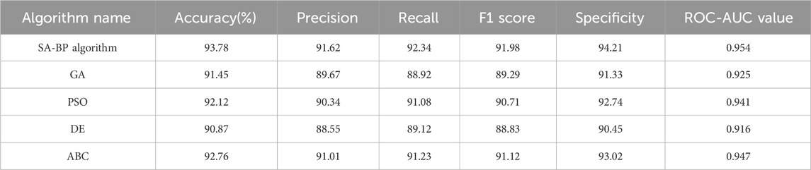
Table 1. Comparison of algorithm performance indicators.
As shown in Table 1, the SA-BP algorithm demonstrated superior performance across all key metrics. It achieved the highest accuracy (93.78%), precision (91.62%), and recall (92.34%). Crucially, it also obtained the top F1 score of 91.98%, indicating the best balance between precision and recall, and the highest ROC-AUC value of 0.954, signifying its excellent overall capability to discriminate between the two classes. While other algorithms like ABC and PSO also yielded strong results, with F1 scores of 91.12% and 90.71% respectively, they did not surpass the balanced performance of the SA-BP model. The GA and DE algorithms showed comparatively weaker performance in this task. Overall, the comprehensive results in Table 1 confirmed that the SA-BP algorithm possessed the most robust and reliable discriminative power for evaluating the quality of manipulator motion paths.
3.2 Performance analysis and verification of SA-BP algorithm combined with PID control in optimizing the motion path of truss manipulator
The SA-BP algorithm combined with a PID controller was used in the experiment to optimize the motion path of the truss manipulator. The PID controller was used to adjust the motion trajectory of the robotic arm to minimize its error. The parameter settings were as follows: the initial value of proportional gain Kp was 0.1, the initial value of integral gain Ki was 0.05, and the initial value of differential gain Kd was 0.01. The sampling period of this experiment was 0.01 s, and the total running time was 3 s. The actual motion data of the robotic arm were fed back to the controller in real-time through sensors, and the PID parameters were optimized using BP NN and SAA to make the movement trajectory of the robotic arm smoother and more accurate. The time-varying curves of the three parameters of the PID controller are shown in Figure 9.
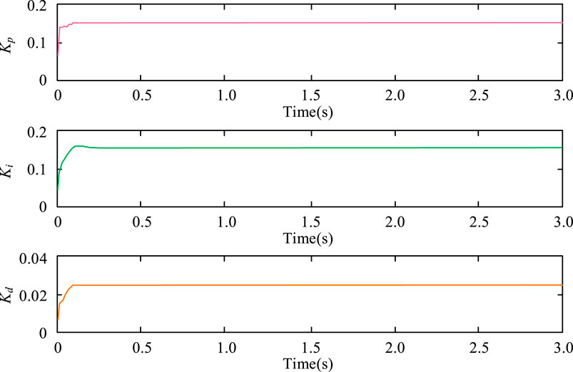
Figure 9. Time dependent curves of the three parameters of the PID controller.
Figure 9 shows the changes in three parameters Kp, Ki, and Kd over time when the SA-BP algorithm was combined with a PID controller in the motion path optimization task of a truss manipulator. Firstly, there was a change in the Kp parameter, which rapidly increased in the initial stage and stabilized at around 0.15 at approximately 0.1 s. Next was the Ki parameter, which rapidly increased to around 0.11 at the beginning and reached a stable value at about 0.2 s. The final curve showed the variation of Kd parameter, which rapidly increased to 0.02 at about 0.05 s and remained unchanged. All three parameters converged to stable values within a brief timeframe, indicating that the algorithm had a fast and stable response speed in PID control. The comparison of optimization algorithm effectiveness for the motion path of the truss robotic arm is represented in Table 2.
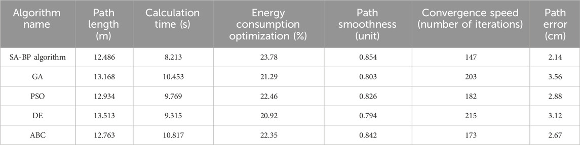
Table 2. The comparison of optimization algorithm effectiveness for the motion path of truss robotic arm.
As shown in Table 2, the SA-BP algorithm performed excellently in key performance indicators, with a path length of 12.486 m, the shortest, energy optimization reaching 23.78%, calculation time of 8.213 s, iteration convergence speed of 147 times, path error of 2.14 cm, smoothness of 0.854, demonstrating high stability. In contrast, the GA path length was 13.168 m, with an optimized energy consumption of 21.29% and a path error of 3.56 cm, showing slightly inferior performance. The PSO algorithm had a path length of 12.934 m, energy optimization of 22.46%, and 182 iterations, slightly slower than SA-BP. The DE algorithm had a path length of 13.513 m, a computation time of 9.315 s, 215 iterations, and the slowest convergence speed. The ABC algorithm had a path length of 12.763 m, optimized energy consumption of 22.35%, smoothness of 0.842, computation time of 10.817 s, balanced performance, and was close to SA-BP. Overall, the SA-BP algorithm demonstrated significant advantages in path optimization, energy consumption, and computational efficiency. The performance of the proposed SA-BP algorithm was comprehensively validated by comparing its generated path against both the original, unoptimized path and a theoretically optimal path, with the results detailed in Table 3.
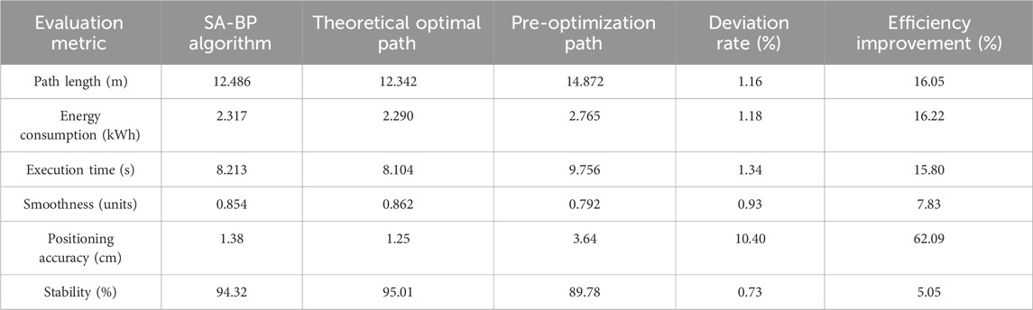
Table 3. Performance validation of truss manipulator motion path optimization model.
As shown in Table 3, the algorithm demonstrated substantial improvements over the pre-optimization baseline across all evaluation metrics. Notably, it reduced the path length from 14.872 m to 12.486 m (a 16.05% improvement) and slashed the positioning error by a remarkable 62.09%, from 3.64 cm down to 1.38 cm. Crucially, the performance of the SA-BP optimized path closely approached the benchmarks set by the theoretically optimal path. The optimized path length, energy consumption, and execution time showed minimal deviation rates of just 1.16%, 1.18%, and 1.34% from the ideal values, respectively. Furthermore, key performance indicators such as smoothness (0.854 units) and stability (94.32%) were also remarkably close to the theoretical best-case scenario, with deviations of less than 1%. This proximity to the ideal benchmark strongly underscored the algorithm’s high efficiency and its capability to converge on a near-optimal solution. To rigorously validate the real-world applicability of the proposed SA-BP algorithm, a final verification experiment was conducted on the physical truss manipulator system described in Section 2.1. In this experiment, a standard pick-and-place task was defined with specified start and end coordinates. The SA-BP algorithm was first used to generate the optimal motion path and corresponding control commands. These commands were then fed directly to the manipulator’s control system. The actual executed trajectory of the manipulator’s end-effector was tracked in real-time using the MPU6050 sensor system. The performance of the predicted path was then compared against the actual executed path. Key performance indicators (KPIs) were measured to quantify the fidelity of the real-world execution against the algorithm’s optimized plan. The comparison between the SA-BP predicted path and the actual execution path on the physical system is shown in Table 4.
Table 4. Comparison of SA-BP predicted path vs actual executed path on physical system.
The results of this direct comparison are presented in Table 4, demonstrating a high degree of correlation between the predicted performance and the physically realized results, thereby confirming the algorithm’s effectiveness and robustness in a practical application scenario.
4 Discussion
The research focused on optimizing the motion path of truss manipulators to solve their positioning deviation problem in industrial automation. The research proposed an optimization method that combined SA and BP NN. The SAA was used to initially optimize path weights, and then the BP NN was applied to further adjust the motion path to improve the precision and energy productivity of path planning. The research results indicated that the SA-BP algorithm outperformed other optimization algorithms in multiple performance metrics. Specifically, the SA-BP algorithm reduced path error to 1.38 cm, improved energy optimization by 16.22%, and reduced execution time to 8.213 s. Meanwhile, the smoothness of the path reached 0.854, significantly better than GA’s 0.803 and PSO’s 0.826. In contrast, GA had a path error of 3.56 cm and an energy optimization rate of 21.29%. These data further proved that the SA-BP algorithm had significant advantages in path optimization and energy saving. Although the research results were satisfactory, there were still some shortcomings in this study. The training time of the model was relatively long, especially when dealing with large-scale data, which might affect the practical application of the algorithm. Future work prospects can further optimize the computational efficiency of algorithms to shorten training time. Meanwhile, incorporating dynamic path planning into the research scope and developing more intelligent and flexible control systems to cope with complex industrial automation scenarios.
Data availability statement
The original contributions presented in the study are included in the article/supplementary material, further inquiries can be directed to the corresponding author.
Author contributions
YH: Writing – original draft, Validation, Methodology, Formal Analysis. JT: Supervision, Data curation, Writing – review and editing, Resources.
Funding
The author(s) declare that no financial support was received for the research and/or publication of this article.
Conflict of interest
The authors declare that the research was conducted in the absence of any commercial or financial relationships that could be construed as a potential conflict of interest.
Generative AI statement
The author(s) declare that no Generative AI was used in the creation of this manuscript.
Any alternative text (alt text) provided alongside figures in this article has been generated by Frontiers with the support of artificial intelligence and reasonable efforts have been made to ensure accuracy, including review by the authors wherever possible. If you identify any issues, please contact us.
Publisher’s note
All claims expressed in this article are solely those of the authors and do not necessarily represent those of their affiliated organizations, or those of the publisher, the editors and the reviewers. Any product that may be evaluated in this article, or claim that may be made by its manufacturer, is not guaranteed or endorsed by the publisher.
References
Agrawal, K., Panda, A., and Sahoo, A. K. (2024). Advancements in tool wear monitoring in turning operations: digital image processing and AI techniques. J. Phys. Conf. Ser. IOP Publ. 2818 (1), 012040. doi:10.1088/1742-6596/2818/1/012040
Aydın, İ., Özbek, A., and Kara, F. (2015). A new approach to minimization of the surface roughness and cutting force via fuzzy TOPSIS, multi-objective grey design and RSA. Measurement 70, 100–109. doi:10.1016/j.measurement.2015.03.037
Cao, S., Yang, M., and Liu, J. (2024). Continuum modeling and boundary control of a satellite with a large space truss structure. Aerospace 11 (1), 54–71. doi:10.3390/aerospace11010054
Dai, Y., Xiang, C., Bao, Y., Qi, Y., Qu, W. Y., and Zhang, Q. H. (2023). Research on orbit assembly strategy of large-scale space truss structure. Recent Pat. Eng. 17 (1), e301221199672–135. doi:10.2174/1872212116666211230121623
Dai, Y., Li, S., Chen, X., Nie, X., Rui, X., and Zhang, Q. (2024). Three-dimensional truss path planning of cellular robots based on improved sparrow algorithm. Robotica 42 (2), 347–366. doi:10.1017/s0263574723001480
Gök, A., Gök, K., Bilgin, M. B., and Alkan, M. A. (2017). The effects of cutting parameters and tool path strategies on tool acceleration in ball end milling. Mater. Technol. 51 (6), 957–965. doi:10.17222/mit.2017.039
Han, B., Yao, Y., Zhou, Y., Xu, Y., Yao, J., and Zhao, Y. (2023). Kinematic and dynamic characteristics' analysis of a scissor multi-rod ring deployable mechanism. Mech. Sci. 14 (1), 193–207. doi:10.5194/ms-14-193-2023
Kara, F., Aydın, İ., and Kisioglu, Y. (2015). Optimization of processing parameters of a developed new driller system for orthopedic surgery applications using taguchi method. Int. J. Adv. Manuf. Technol. 76, 1437–1448. doi:10.1007/s00170-014-6327-0
Liu, B., Zhang, W., Duan, W., and Meng, Q. (2023a). BP neural network modeling and solving acceleration of analog ICs. Circuits, Syst. Signal Process. 42 (12), 7023–7044. doi:10.1007/s00034-023-02443-x
Liu, C., Yu, S., and Yim, M. (2023b). Motion planning for variable topology trusses: reconfiguration and locomotion. IEEE Trans. Robotics 39 (3), 2020–2039. doi:10.1109/tro.2022.3228400
Pei, J., Xu, L., Huang, Y., Jiao, Q., Yang, M., Ma, D., et al. (2023). A two-step simulated annealing algorithm for spectral data feature extraction. Sensors 23 (2), 893–907. doi:10.3390/s23020893
Rehman, S., Nuha, H., Shaikhi, A., Akbar, S., and Mohandes, M. (2023). Improving performance of recurrent neural networks using simulated annealing for vertical wind speed estimation. Energy Eng. 120 (4), 776–789. doi:10.32604/ee.2023.026185
Suvorov, V., Vasilyev, R., Melnikov, B., Kuznetsov, I., and Bahrami, M. R. (2023). Weight reduction of a ship crane truss structure made of composites. Appl. Sci. 13 (15), 8916–8929. doi:10.3390/app13158916
Tsoulos, I. G., Charilogis, V., and Tsalikakis, D. (2024). Train neural networks with a hybrid method that incorporates a novel simulated annealing procedure. AppliedMath 4 (3), 1143–1161. doi:10.3390/appliedmath4030061
Yaldız, S., Ünsaçar, F., and Kara, F. (2013). Cutting parameter and tool path style effects on cutting force and tool deflection in machining of convex and concave inclined surfaces. Int. J. Adv. Manuf. Technol. 69 (5-8), 1063–1078. doi:10.1007/s00170-013-5075-x
Yaldız, S., Ünsaçar, F., and Gök, K. (2016). Determination of experimental, analytical, and numerical values of tool deflection at ball end milling of inclined surfaces. Proc. Institution Mech. Eng. Part E J. Process Mech. Eng. 230 (2), 111–119. doi:10.1177/0954408914540633
Yan, Y., Zhang, W., Liu, Y., Liu, Y., and Li, Z. (2023). Simulated annealing algorithm optimized GRU neural network for urban rainfall-inundation prediction. J. Hydroinformatics 25 (4), 1358–1379. doi:10.2166/hydro.2023.006
Yin, Z., Huang, X., Yi, B., Han, T., and Wang, C. (2023). Assistant investigation of energy dissipation in non-obstructive particle damper based on a neural network using simulated annealing backpropagation. J. Vib. Control 29 (23-24), 5387–5397. doi:10.1177/10775463221135207
Keywords: truss manipulator, motion path optimization, simulated annealing algorithm, BP neural network, industrial automation
Citation: Huang Y and Tian J (2025) Motion path optimization of truss manipulator based on simulated annealing and BP neural network. Front. Mech. Eng. 11:1643848. doi: 10.3389/fmech.2025.1643848
Received: 09 June 2025; Accepted: 08 September 2025;
Published: 24 September 2025.
Edited by:
Mohamed Arezki Mellal, University of Boumerdés, AlgeriaCopyright © 2025 Huang and Tian. This is an open-access article distributed under the terms of the Creative Commons Attribution License (CC BY). The use, distribution or reproduction in other forums is permitted, provided the original author(s) and the copyright owner(s) are credited and that the original publication in this journal is cited, in accordance with accepted academic practice. No use, distribution or reproduction is permitted which does not comply with these terms.
*Correspondence: Jieyu Tian, dGlhbmppZXl1aGJAMTYzLmNvbQ==