 Tukaram Patil
 Dinesh Washimkar2†
 Ashish Pawar
 Mithul Naidu
 Sachin Shinde
 Sachin Salunkhe
- 1Department of Mechanical Engineering, VIIT Pune, Pune, Maharashtra, India
- 2Vishwakarma Institute of Technology, Pune, Maharashtra, India
- 3Dr. Vishwanath Karad MIT World Peace University, Pune, Maharashtra, India
- 4Faculty of Mechanical Engineering, Tolani Maritime Institute, Pune, India
- 5Department of Mechanical Engineering, Datta Meghe College of Engineering, Navi Mumbai, India
- 6Department of Biosciences, Saveetha School of Engineering, Saveetha Institute of Medical and Technical Sciences, Chennai, India
- 7Gazi University Faculty of Engineering, Department of Mechanical Engineering, Ankara, Türkiye
A friction stir-based material processing technique for improving the surface and microstructural characteristics of materials is called friction stir processing (FSP). Because FSP involves severe deformation caused by plasticity, material flow, heat transport, and microstructure evolution, it is a multi-physics problem that can be difficult to describe. The performance of the friction stir process is influenced by several factors, including plastic deformation, material flow, temperature, and residual stresses. Enhancing the process requires developing a numerical model that considers these influencing parameters for a specific workpiece material.
Lightweight materials such as aluminum alloys offer high specific strength and ductility, making them ideal for applications in the automotive and aerospace industries. Today’s industries are primarily interested in metallic alloys that are lightweight and strong. Because of their low weight, aluminum alloys hold a special place in the industry. Much effort is being made to improve the mechanical qualities of aluminum through a surface modification technique called FSP. This study reviews the literature on the FSP of the AA7075 alloy, focusing on the influence of key parameters such as rotational speed, traverse speed, and machining conditions. Modeling and simulations of FSP for material change have not been extensively studied. This study uses ABAQUS/Explicit to create a computationally efficient process model based on the coupled Eulerian–Lagrangian (CEL) formulation to simulate the FSP of aluminum alloy. Tool plunging, dwelling, and stirring phases are all included in the simulation of the full FSP process using the three-dimensional (3D) finite-element model. The impact of tool rotational speed and tool pin profile during the FSP process is assessed using simulations. Comparing the proposed model’s computational efficiency to that of other models currently in use for friction stir welding procedures is another way to assess its effectiveness. To validate the model, the FSP experiment is conducted using temperature and process force measurements. This work shows that the CEL model can be a useful numerical tool for simulating complex process mechanics and optimizing FSP process parameters for industrial applications.
1 Introduction
Appropriate material selection with a specific set of properties is an important parameter in the industry. The automobile and aircraft industries, in particular, are focused on specific material selection to reduce the overall weight of the components. Aluminum alloys are currently the preferred materials in those industries. The processing of metal alloys with variable strength affects the cost and production time. Materials with fine, uniform grain structures exhibit high strength and good ductility. Therefore, a processing method that can yield a material with a small grain size must be used. These days, processing techniques include equal channel angular extrusion (ECAE) and friction stir processing (FSP) in addition to powder metallurgy and the Rockwell process. To enhance surface and local features at certain locations, FSP expands upon the friction stir welding (FSW) technology developed in 1991 by the Welding Institute (TWI) in the United Kingdom.
FSP is a unique and innovative thermomechanical processing technique that optimizes performance while reducing manufacturing time and costs by changing the material’s mechanical and microstructural properties in a single pass. Figure 1 depicts the FSP schematic. A specifically made cylindrical tool with a large diameter shoulder and a small diameter pin is used in this technique. During its rotation, it is plunged into the chosen location. By rapidly heating and softening a tiny metal column, friction between the rotating pin and the sheet surface allows the tool to pass transversely through the material when it is inserted. The penetration depth is controlled by the probe length and tool shoulder. During FSP, the region to be processed and the tool are shifted relative to each other so that the tool goes over the entire selected area in overlapping passes until the required fine-grain size is achieved. As the tool moves through the processed zone, it cools and forms an equiaxed fine-grain microstructure that is free of defects and dynamically recrystallized.
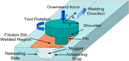
Figure 1. A schematic drawing of friction stir processing (Edwards and Crouch, 2017).
According to numerous studies, FSP is an affordable option for the automotive and aerospace sectors. The microstructural behavior of aluminum alloys in the friction stir process has been studied by numerous researchers (Aalco, 2021; Mukhopadhyay, 2010; Mukhopadhyay, 2012a; Mukhopadhyay, 2012b; Chawla and Gupta, 1993; Wang et al., 2006; Edwards et al., 1998; Totik et al., 2004; Pan et al., 2016; Robson, 2004; Wang et al., 2011; Xu et al., 2017). Their investigation’s primary goal is to examine the areas impacted by heat and grain processing. It has been noted that the FSP of commercial aluminum alloys 1100, 2024, 5083, 6061, 7075, and 7475 significantly improves their superplastic qualities. Researchers have investigated the hardness, fatigue, micro texture, and tensile strength of several aluminum alloys (Wang et al., 2008; Lin et al., 2006; Wei et al., 2004; Vailey et al., 2000; Valiev et al., 2016; Bagherpour et al., 2019; Zendehdel and Hassani, 2012; Valiev and Langdon, 2006; Hong et al., 2014; Bhovi et al., 2016; Toroghinejad et al., 2013). Finite element analysis, numerical process modeling, and experimental investigation are also used to examine the heat produced and residual stress during the process. This idea requires further research to optimize the obtained finer grain size as a function of specific process parameters, such as tool geometry, rotational and translational speeds, etc.
2 Materials and methods
2.1 Lightweight aluminum alloys
At present, a great variety of materials such as metals and their alloys, ceramics, plastics, and composites are available for engineering applications with their own traits, standards, and limitations. They are used either singly or in combination for a particular application. Selection of the ideal material having expected application-dependent properties is an essential feature in every industrial application as it improves the function, quality, performance, properties, and cost of the product/component. After the selection of material, the use of an appropriate manufacturing process for the targeted application is equally important.
In this section, a broad outline of the current scenario, in reference to data available in the literature relating to the importance and use of light metal alloys, is furnished. Metals or alloys having low density, high specific strength, and low toxicity are termed light metal alloys (LMA) or simply light alloys (LA). Generally, magnesium, aluminum, and titanium alloys are considered light alloys; owing to its toxic nature, beryllium is excluded from this category (Edwards and Crouch, 2017). A plot showing relative bulk densities of commonly used alloys is presented in Figure 2. Light alloys are of great importance in aerospace, automobile, defense, and medical industries, where a high strength-/stiffness-to-weight ratio is imperative to warrant their use by reducing mass and increasing efficiency (Monteiro, 2014). The cost and blend of properties of Al alloys, viz., high specific strength, superior formability, excellent cast ability, and electrical/thermal conductivity, along with excellent corrosion resistance make these alloys appropriate for a wide range of uses. To increase fuel efficiency and reduce greenhouse gas emissions, they are utilized as a structural material in the automotive sector to produce space frames, engine brackets, engine blocks, cylinder heads, brake rotors, and interior body panels (Davis, 1993). They are also utilized in manufacturing aircraft structural components and marine engines (Spada, 2002; Dorum et al., 2009; Hatch, 1984). To serve the purpose, the current study is focused on Al alloys.
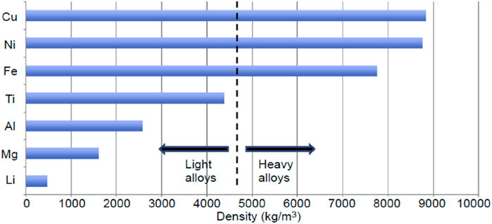
Figure 2. Relative bulk densities of metallic alloys (Edwards and Crouch, 2017).
Aluminum is the most abundantly produced and utilized non-ferrous metal around the world. Compounds of aluminum have been used for several hundred years. The first commercial production of aluminum started about 170 years ago. Since then, the demand for Al and its alloys has increased and has reached approximately 29 million tons per year (Aalco, 2021). Low density (around 2.7 gm/cc), high strength (achievable through alloying and heat treatment), and excellent corrosion resistance are the three key attributes together with supplementary traits like high electrical/thermal conductivity, high ductility, non-magnetic nature, low working cost, and high recyclability of Al alloys, make them suitable for many engineering applications (Mukhopadhyay, 2010; Mukhopadhyay, 2012a). Al alloys are used as armor material for lightweight combat vehicles and form the core structure of scout vessels and the superstructure of large ships. Frigates and destroyers are also fabricated using Al alloys. Both commercial and military aircraft are manufactured using high-strength Al alloys as structural material. Because the ductile to brittle transition temperature (DBTT) of Al alloys is very low and they do not undergo embrittlement at low service temperatures, they are utilized to produce cryogenic fuel tanks for rockets and launch vehicles (Mukhopadhyay, 2012b).
Typically, Al alloys are categorized as cast alloys and wrought alloys (non-heat-treatable and heat-treatable wrought alloys). The fraction of alloying elements is higher, and the tensile strength is lower, in cast Al alloys than in wrought Al alloys. Cast Al alloys are utilized in the cast condition. Their applications include window fittings, garden tools, gearbox and axle housings, cast wheels, and farm equipment. Wrought Al alloys are worked in the solid state using specific tools to form them into various standard and nonstandard shapes. They possess better mechanical properties, structural integrity (no casting defects), and surface finish than cast Al alloys. Al alloys that cannot be strengthened by age-hardening heat treatment are called non-heat-treatable wrought Al alloys. Typically, they are strengthened by cold working through mechanical reduction. Al alloys that respond to age (precipitation) hardening heat treatment to attain reasonably high strength levels are called heat-treatable wrought Al alloys.
Alloying elements play a vital role in heat treatability and properties of Al alloys. The elements Cu, Zn, Mg, Si, Mn, and Li are the principal alloying elements used to strengthen the Al alloys. Table 1 shows a four-digit numerical designating system used to specify wrought Al alloys. Out of these four digits, the first digit denotes the chief alloying element, the second digit denotes the variation of the alloy, and particular alloys in the series are represented by the third and fourth digits (Chawla and Gupta, 1993). Al alloys are also specified by the temper designation system, which depends on the series of mechanical and/or thermal treatments given to an alloy, such as O (annealed), H (strain-hardened), F (as fabricated), or T (thermally treated) (Chawla and Gupta, 1993; Bhojak et al., 2023; Pawar et al., 2024).
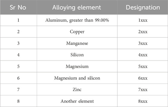
Table 1. Designation of wrought Al alloys (Wang et al., 2006).
Precipitation (age) hardening is one of the most extensively exercised mechanisms for the strengthening of metallic materials. The strongest Al alloys, viz., 2xxx, 6xxx, and 7xxx, are developed by precipitation hardening heat treatment. The hardness and strength of a few metallic alloys are attained by the evolution of homogeneously distributed tiny precipitates within the parent matrix through the heat treatment process, called precipitation or age hardening (Wang et al., 2006). This extremely fine precipitate hinders the motion of dislocations by obstructing their path and ultimately results in the strengthening of the heat-treated alloys (Edwards et al., 1998). Precipitation hardening depends on the variation in solid solubility with temperature to produce tiny precipitates. An alloy system can be precipitation-strengthened only if there is a formation of a terminal solid solution at elevated temperature and solid solubility decreases with a drop in temperature (Wang et al., 2006; Totik et al., 2004). Three basic steps that are involved in the process of precipitation hardening are listed below and presented using Figure 3.
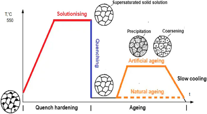
Figure 3. Steps of precipitation hardening (Wang et al., 2006).
Solution zing is also called solution annealing. It involves the heating of the alloy above the solvus temperature within the single-phase region. It is held at that temperature to dissolve all the alloying elements and form a homogeneous solid solution. The quenching is rapid cooling using a quenching medium to obtain a supersaturated solid solution (SSSS). The aging consists of reheating a supersaturated solid solution (SSSS) to a medium temperature (lower than the solvus temperature) to attain a finely dispersed precipitate particle. High strength in the 2xxx, 6xxx, 7xxxx, and 8xxx series Al alloys can be attained via age hardening. In the 2xxx series, the principal alloying element is Cu, which readily responds to age hardening and forms high-strength precipitates like CuAl2 and Al2CuMg. 2xxx series Al alloys possess high strength, toughness, and fatigue resistance. Mg and Si are the chief alloying elements of the 6xxx series. Formation of precipitates like Mg2Al3 and Mg2Si during age hardening results in strengthening of these alloys. Low fracture toughness of these alloys limits their use in aerospace and defense applications (Pan et al., 2016). Li is the key alloying element in the 8xxx series Al alloys. Though the addition of lithium in aluminum matrix reduces density and improves elastic modulus and tensile strength, the high cost of lithium metal and the high processing cost of Al–Li alloys limit their applicability (Robson, 2004). Zn, Cu, and Mg are the principal alloying elements in 7xxx series Al alloys (Pan et al., 2016; Robson, 2004). During precipitation hardening of these alloys, precipitates like CuAl2, Mg2Al3, Al32 (Mg, Zn) 49, and MgZn2 are formed, which contribute to strengthening, and the yield strength achieved is in the range of 450–600 MPa (Zendehdel and Hassani, 2012). 7xxx series Al alloys usually have superior strength and hardness to 2xxx alloys; therefore, they are used in defense and aircraft structural applications where higher stresses are imparted (Xu et al., 2017). Al alloy 7075 (AA7075) is the most abundantly utilized alloy in the defense and aerospace industries among all of the 7xxx series Al alloys.
AA7075 was established by the Aluminum Company of America in 1943 with Zn as the principal alloying element. Zn, Cu, and a small fraction of other alloying elements act as hardeners to strengthen the alloy by forming tiny intermetallic/precipitates during the age-hardening process (Fernandez et al., 2010). The alloy possesses exceptional strength, good ductility, and toughness together with excellent fatigue resistance (Wang et al., 2008). The corrosion resistance of AA7075 is considerably superior to that of the 2xxx series Al alloys, but it is more notch sensitive (has a higher embrittlement tendency) than most of the Al alloys (Lin et al., 2006). When annealed, it has excellent formability and machinability. The main disadvantage of AA7075 in the high-strength T6 temper condition is its high susceptibility to stress corrosion cracking (SCC). However, this can be addressed by using retrogression and re-aging (RRA) heat treatment, which increases resistance to SCC without compromising the alloy’s strength (T6 condition). AA7075 is widely used in structural elements of automobiles, armed vehicles, bridges, large earth-moving equipment, aircraft, and many other high-end applications because of its special combination of properties (Wei et al., 2004).
2.2 Friction stir processing
Metal working techniques that involve very large plastic strains and complex state of stresses resulting in very high defect density along with ultrafine grain structure are called severe plastic deformation (SPD) techniques (Vailey et al., 2000). Recently, many researchers have been exploring various SPD techniques to fabricate bulk ultrafine-grained (UFG) materials with superior properties (Valiev et al., 2016). Using SPD techniques to manufacture bulk UFG materials with high grain boundary disorientation and relatively homogenous and equiaxed microstructures has clear uses in the creation of high-strength materials. Numerous studies are being conducted to enhance SPD methods that can commercially produce UFG metals and alloys. The most crucial feature of these techniques is that the workpiece’s exterior dimensions do not change much during or after processing (Bagherpour et al., 2019). To date, there have been reports of around 120 distinct SPD techniques with a range of deformation modes for varied material geometries and forms (Zendehdel and Hassani, 2012). These include MDF (multidirectional forging), RCS (repeated corrugation and straightening), TE (twist extrusion), HPT (high pressure torsion) (Valiev and Langdon, 2006), ECAP (equal channel angular extrusion/pressing (Hong et al., 2014), and ARB (accumulative roll bonding) (Mishra et al., 2000).
Mishra et al. (2000) used projected friction stir processing (FSP) and the basic philosophy of friction stir welding (FSW) as a new SPD technique for microstructural modification in 1999. Without altering the plate’s shape or size, FSP creates a submicron-level ultra-fine-grain structure by applying enormous shear strain to the material. FSW was created in 1991 by the Welding Institute (TWI), UK, and since then, there have been multiple documented process modifications of this technology. A revolving tool with a shoulder and a joining pin is used in the solid-state metal joining process known as FSW. To join two metal sheets, the pin is inserted into their interface and passed through (Lockwood et al., 2002). A recrystallized weld stir zone microstructure is the unique feature of the resulting joint produced via FSW that typically has a finer grain structure than the base metal (Mishra and Ma, 2005). During FSP, a rotating tool is traversed across a single piece of material to modify the microstructure, properties, and, sometimes, the composition (Mishra, 2004).
FSP may be the most significant and extensively studied variety of the friction stir technique due to its unique features, which include minimal heat generation, mechanical mixing, huge material flow, high forging pressure, ultra-fine-grain structure, and random disorientation of grain boundaries (Charit and Mishra, 2005). FSP is basically a local thermomechanical metal working method, wherein the tool is plunged into the workpiece and then traversed along a desired path to alter the localized microstructure (Arbegast, 2003). Localized heating and softening of the friction between the tool and the workpiece causes the substance to form. A small volume of plasticized material flows from the front of the pin (advancing side) to the back of the pin (retreating side). This leads to intense plastic deformation of the material and results in a significant increase in defect density. Simultaneous heat generation and plastic flow of material eventually result in dynamic recrystallization.
2.3 Flow of materials during FSP
Numerous factors, including process parameters, tool shape, and tool material, affect the flow of plasticized material during FSP, making it exceedingly complex and leaving little knowledge of the deformation process (Charit and Mishra, 2005; Arbegast, 2003; Besharati-Givi and Asadi, 2014; Grujicic et al., 2010). According to Arbegast et al. (Besharati-Givi and Asadi, 2014), the material flow during FSP can be depicted as five basic working zones for metal: (i) Preheat. (ii) Initial deformation. (iii) Extrusion. (iv) Forging. (v) Post heat/cool down, as shown in Figure 4a. Temperature increases ahead of the pin because of the frictional heat produced by the rotating tool and adiabatic heat originating from material deformation. This is called the preheat zone, and the heating rate of this zone is governed by the thermal characteristics of the material together with the tool traverse speed. As the tool begins traversing forward and the temperature of the material increases beyond the critical temperature (the temperature required to start material flow), an initial deformation zone forms and leads to material flow. Furthermore, as shown in Figure 4b, an extrusion zone with a finite width is formed, wherein material travels around the pin from the front to the back. Under hydrostatic pressure, material entering the forging zone from the tool’s front is pushed into the hole left by the pin. Finally, cooling of material takes place under either forced or passive cooling conditions.
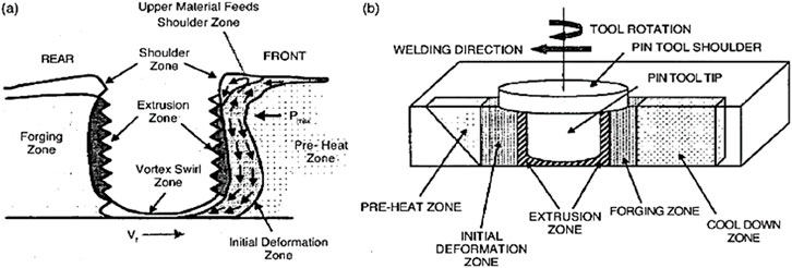
Figure 4. (a) Schematic diagram showing material flow and (b) fundamental metal working zones generated during FSP (Valiev and Langdon, 2006).
Microstructural changes in the material occur because of material flow during FSP. As illustrated in Figure 5 (Charit and Mishra, 2005; Arbegast, 2003; Besharati-Givi and Asadi, 2014; Grujicic et al., 2010), the microstructure of the friction stir-processed (FSPed) specimen essentially exhibits four different zones: the stir zone (SZ), the transition zone (TZ), the heat-affected zone (HAZ), and the base metal (BM).
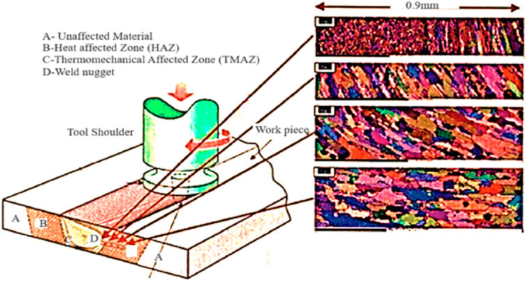
Figure 5. Different microstructural zones produced during FSP (Hong et al., 2014).
The SZ, sometimes referred to as the nugget zone (NZ), is characterized by a very fine, recrystallized, and nearly equiaxed grain structure. It represents the location of the pin during processing and hence experiences the highest strain and temperature. Often, a few concentric rings can be observed in the SZ known as an “onion-ring” structure, which is a distinctive feature of this zone. The TZ, also known as the thermomechanically affected zone (TMAZ), appears in close vicinity and on either side of the SZ. It is subjected to the thermal cycle and mechanical stress. The strain and temperature in TZ are lower than those of SZ. Mostly deformed and rotated grain structure and sometimes, mixed microstructure comprising bulky and fine grains are observed in this zone. The HAZ is commonly observed in most of the thermomechanically processed materials. In an FSP specimen, it is present between TZ and BM. Material experiences thermal cycle without any plastic deformation in the HAZ. Though the peak temperature in this zone is less than that in TZ, it still has a noteworthy impact if the microstructure is thermally unstable. The BM is the region that is unaffected by the FSP.
3 Parameters affecting FSP
FSP involves complex material movement. Due to high strain rates, the pattern of plastic deformation and thereby microstructure evolution is also complex. Processing parameters, tool material, and its geometry have a major impact on the temperature distribution and material flow pattern, and therefore, they have a strong influence on the microstructure evolution and associated material properties. A few major parameters affecting the FSP process are stated below.
3.1 Tool rotation speed
Tool rotation speed is also referred to as spindle speed. It is the rate at which the tool rotates during processing and is measured in terms of revolutions per minute (RPM). It has a remarkable influence on the material flow and heat input (Mishra, 2004). The ideal tool rotation speed is established on the basis of the material to be processed. Although there is a complicated relationship between rotational speed and processing heat, it would seem that increasing rotation speed will result in more heat input and potentially lower-quality processed material (Simar et al., 2012). In addition, premature tool wear, chatter, and tool breakages may occur due to excessive rotational speed. Using the correct rotation speed will significantly influence tool life and the quality of processed material (Zhang et al., 2012).
3.2 Tool traverse speed
The tool traverse speed is also called the feed rate. It is the travel speed at which the tool advances against the workpiece and is measured in terms of inches per minute (ipm) or millimeters per minute. It has a strong influence on the overall thermal cycle. It has been stated that decreasing the traverse speed will lead to higher heat input and vice versa (Mishra, 2004). It is reported that lower than the required heat input causes voids or other flaws in the SZ, and, in a worst case, the tool may break, whereas excessive heat input results in poor quality of processed material because of the liquation of low-melting point phases. To facilitate the successful and defect-free processing (FSP), the ideal combination of rotation and traverse speed is necessary, which will ensure the optimum heat input required for extensive plastic flow of the material and reduce the tool’s acting forces (Mishra, 2004).
3.3 Plunge depth
One of the most important process characteristics for good processing quality is the depth to which the shoulder penetrates inside the workpiece during FSP. The pressure below the tool increases by plunging the shoulder below the workpiece, and it leads to sound forging of the material at the back of the tool. Precise setting of the plunge depth is necessary to generate sufficient downward pressure and to ensure the complete penetration of the tool inside the workpiece. Plunge depth that is either less than or more than adequate may cause defects during FSP and deteriorate the quality of processed material (Grujicic et al., 2010).
3.4 Tool tilt angle
The angle between the spindle shaft and the plane normal to the workpiece is called the tool tilt angle. Generally, it is kept between 0° and 3°. It helps to forge the material in the cavity left by the FSP tool (Mishra et al., 2000).
4 Friction stir processing tool
A non-consumable tool, featuring a pin (probe) and the shoulder as its main components, is used for FSP. It is the most critical component to the success of the process during the thermomechanical processing. The main functions of the FSP tool are (i) generating the required heat through friction; (ii) stirring, mixing, and dragging the plasticized material from the front of the pin to the back in the cavity; (iii) constraining the processed material under the tool shoulder (Mishra et al., 2000). Overall, the tool design (tool material and geometry) has a strong influence on the workpiece frictional heating, which causes material flow and the thermomechanical deformation during FSP (Hong et al., 2014). Tool design and material selection greatly influence the tool life, quality, and cost of processing. In recent times, many novel tool materials and geometrical features have been incorporated and examined pertaining to FSP tool design (Mishra et al., 2000).
4.1 Tool types
As shown in Figure 6, depending upon the type of pin (probe), three different types of FSP tools have been reported, viz., fixed, adjustable, and self-reacting. The tool, which is fabricated as a single piece comprising both the shoulder and the probe (pin), is called a fixed probe tool (Figure 6a). It can be used to process the workpiece with a specific thickness only because the pin length is fixed (T et al., 2010). In the case of an adjustable probe tool (Figure 6b), the shoulder and the probe are fabricated separately and then assembled to allow adjustment of the pin length. Two different materials can be used to fabricate the shoulder and the pin. Both the fixed and the adjustable tools need a backing anvil (T et al., 2010). The bobbin tool is made by assembling three separate parts—the top shoulder, probe, and bottom shoulder—as shown in Figure 6c. It does not require a backing anvil to process workpieces of different thicknesses (Mishra et al., 2000).
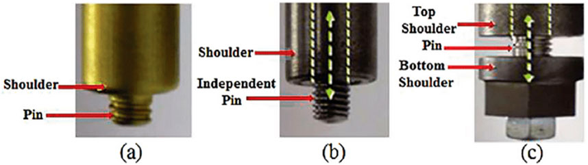
Figure 6. Types of FSW/P tools: (a) fixed probe, (b) adjustable probe, and (c) bobbin probe type (Skinner and Edwards, 2003).
4.2 Tool geometry
As the research on friction stir welding/processing (FSW/P) develops, new geometrical features are being developed and adapted concerning FSP tool design (Mishra et al., 2000). With the invention of novel tool geometries, the material flow around the pin has become more complex, and it is generally unique for a particular tool geometry (Mishra et al., 2000). The key parameters in determining the processing speed and the quality of the processing are shoulder profile, shoulder diameter, pin profile, pin length, and pin diameter (Mishra et al., 2000).
4.3 Tool shoulders
The main function of a tool shoulder is to generate the frictional heating necessary to plasticize the material of the workpiece during FSP. Figure 7 illustrates the most typical shoulder shapes and features (Rai et al., 2011). Concave shoulder geometry is the most commonly used shoulder design in FSW/P (Zhang et al., 2012). Its ability to restrict material extrusion from the sides made it more popular than other shoulder designs (Sharma et al., 2018). Typically, the concavity angle used ranges between 6° and 10°, and due to its simple shape, it is easy to fabricate. It can produce sound (without defect) and high quality FSP. Geometric features, such as concentric circles, ridges, scrolls, knurling, or grooves, can be incorporated on the shoulder surface to increase frictional heat and material flow. Other potential shoulder shapes are shoulders with a flat surface or a convex profile. Earlier convex end profile shoulders were not frequently used because they tended to push the material away from the pin (Sharma et al., 2018); however, their ability to process complex curvature makes them suitable for processing/joining different-thickness workpieces (Lockwood and Reynolds, 2002).

Figure 7. Shoulder shapes and features (Skinner and Edwards, 2003).
4.4 Tool pins (probes)
Material deformation and frictional heating are the two main functions of an FSW/P tool pin. This tool component is made to (i) produce enough frictional heat; (ii) shear and soften the material in front of it; (iii) transport the softened metal to the tool’s back side. The tool pin is largely responsible for controlling the depth of processing in FSP and speed (Sharma et al., 2018). Tool pin geometry has a significant impact on the flow of plasticized material and is closely correlated with the FSP quality (Liu et al., 2020; Leszczynska-Madej et al., 2024; Huang et al., 2023).
4.5 Tool materials
The selection of tool material for FSW/P depends upon the desired tool life and the workpiece material. Appropriate tool material selection results in good quality FSP material for the desired application. The requirement of tool materials for FSP of soft metal alloys (magnesium, aluminum, etc.) is not very stringent. However, there are challenges in developing cost effective and durable tools for FSW/P of harder alloys (nickel, titanium, and steels, etc.) (Pawar et al., 2024) that will consistently produce commercially viable and structurally sound products.
FSP tool material properties, viz., mechanical strength, wear resistance, hardness, fracture toughness, thermal conductivity, and coefficient of thermal expansion, influence the product quality, tool life, and performance (Zhang et al., 2012). An FSW/P tool should not react with either the workpiece material or atmospheric oxygen and keep its dimensional stability without losing geometrical features (Sharma et al., 2018). The material and tool compatibilities are shown in Table 2.
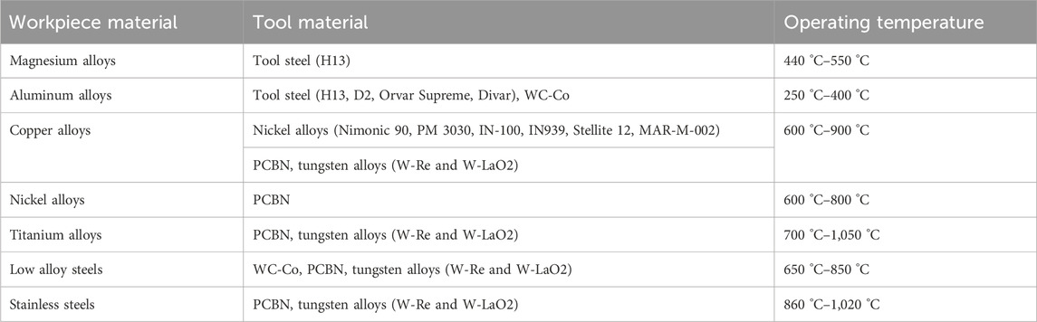
Table 2. FSP tool materials used for various workpiece materials (Rai et al., 2011).
5 Thermal modeling
To model the material flow pattern during the FSW of AA2024, Heurtier et al. (2022) proposed a new mechanical analysis, from which the relevant strain and temperature maps were derived. The process generated a flow that was derived from the velocity fields of classical fluid mechanics. Ulysse (2002a) used 3D visco-plastic modeling to model stir welding. According to that study, pin forces rise as weld speeds and rotational speeds decrease. Additionally, it looked at how varied rotating and welding rates affected the tool’s forces and how tool speeds affected plate temperature. Song and Kovacevic (2003) created a 3D heat transfer model for FSW. They developed a moving coordinate to make modeling a moving tool easier. The model took into account the heat input from the tool shoulder and the pin. The control equations were solved using the finite difference method, and the outcomes showed good agreement with the experimental findings. Their main finding was that FSW benefited from the workpiece’s prior heating. This model facilitated the determination of the temperature distribution. This model makes it easy to determine the temperature distribution over the moving tool pin. Both the tool and the workpiece can be used with this model. To get behind the spinning pin, tool pins frequently slide from the side they are retreating. Additionally, they investigated the variations in velocity fields derived from two distinct models of the tool–material interaction.
Song and Kovacevic (2003) developed a 3D heat transfer model for FSW. They included a moving coordinate to facilitate the modeling of a moving instrument. The model took into account the heat input from the pin and the tool shoulder. The control equations were solved using the finite difference method, and the outcomes showed good agreement with the experimental data. Their work’s key finding was that FSW benefited from the workpiece’s earlier heating. The model made figuring out the temperature distribution easier. The friction between the shoulder, the probe, and the material serves as the model’s heat source.
Numerical simulation offers a quantitative framework for comprehending the dynamics of the FSW thermomechanical process. This also sheds light on the friction-stir weld’s thermal history and the development of longitudinal, lateral, and through-thickness stress. In order to simulate the FSP of aluminum alloy 5083, a computation-efficient process model based on the coupled Eulerian–Lagrangian (CEL) formulation was developed using ABAQUS/Explicit (Ali Ansari et al., 2018). The effects of tool pin profile and rotational speed during the FSP process are assessed through simulations (Ali Ansari et al., 2018) as presented in Table 4. To simulate complex process mechanics and optimize FSP process parameters for industrial applications, this work demonstrates the potential of the CEL model as a potent numerical tool. The experimental findings supported the proposal by Asadi et al. (2011) to use DEFORM 3D software, which was created based on Lagrangian implicit, for a thermomechanical simulation of FSP. Simulation is an excellent way to forecast distributions of effective strain and temperature. The simulation was used to determine the material’s temperature and effective strain around the tool pin. The peak temperature and effective strain required for recrystallization at the bottom of the SZ and the sides that were moving forward and backward, were determined as presented in Table 4. Thus, the simulation can be used to anticipate the breadth of the SZ.
6 Advances in friction stir processing and aluminum alloy composites
According to Sahdev et al. (2021), the mechanical and microstructural features of the stir zone can be accurately supervised by adjusting the parameters of tool design, material properties, FSP parameters, and active heating and cooling as presented in Table 4. A three-dimensional heat transfer model for FSP and a numerical inverse approach are developed to predict the Coulomb friction coefficient by integrating optimization, finite-element simulations, and experimental testing. Chintalu et al. (2021) proposed a three-dimensional transient thermal model based on finite elements to predict the thermal history during FSP of AA5052. In compliance with the stated experimental design, the three parameters of shoulder diameter, tool traverse speed, and tool rotation speed are changed as presented in Table 4. The finite-element model is used to forecast the thermal history for different combinations of parameters. A regression model is developed to examine the impact of process parameters on the thermal history, utilizing the findings of the numerical model.
Deore et al. (2019) suggested surface composites based on AA7075 that are reinforced with various filler materials. Electron backscattered diffraction (EBSD), x-ray diffraction (XRD), and optical and scanning electron microscopy (OM and SEM) were used to characterize the microstructural evolution of aluminum matrix surface composites that have been friction stir-treated with regard to the respective impacts of various filler materials and the ensuing age hardening as presented in Table 4. According to Kumaraswamy et al. (2023), aluminum alloy composite materials are widely used in highly scientific applications because of their low weight, high strength, and improved tribological qualities. Aluminum oxide (Al2O3) and boron carbide (B4C) particles were reinforced using the sand mold technique in an electric resistance furnace to create the Al7075 hybrid composite. This work examined the mechanical behavior of hybrid composites made of Al7075, Al2O3, and B4C with stable Al2O3 contents of 2% and varied B4C weight percentages ranging from 2% to 6%. Both pure and cast specimens were tested for mechanical attributes such as hardness, microstructure analysis, and tensile and compressive strength as presented in Table 4. The mechanical properties of the hybrid composites made from Al7075 alloy were experimentally investigated and validated in this study using the ASTM standard and FEA. The findings show that while tensile strength decreased, mechanical properties, including compressive strength and hardness, increased when hard ceramic particles (Al2O3/B4C) were introduced to a matrix alloy (Al7075). ANSYS successfully replicated the static structural tensile test. A correlation between the analytical and FEA results was found.
Akabari et al. (2023a) used numerical techniques to investigate the effects of process factors, such as welding speed and rotation speed, on material flow, temperature, and strain are investigated shown in Figure 8, and friction stir welding between AA5083 and AA7075 was suggested as presented in Table 3. Using a coupled Eulerian–Lagrangian (CEL) technique, the temperature, strain, and material mixing during the welding of AA7075 and AA5083 alloys were examined as presented in Table 4. When comparing the stir zone (SZ) of the simulation-modeled and experimentally fabricated samples, it was found that the CEL approach had correctly predicted the mixing of materials in the SZ. As the rotating or welding speed increases, the material flow simulation shows that at the higher surfaces of the sheets, AA7075 is more stretched toward AA5083, suggesting a higher material flow density.
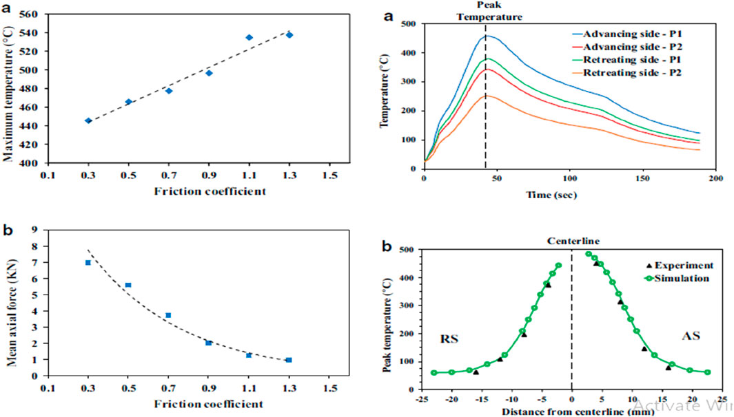
Figure 8. (a) Thermocouples for measuring temperature (b) A comparison of the simulated and experimental temperature distributions away from the centerline of the workpiece (Ali Ansari et al., 2018).
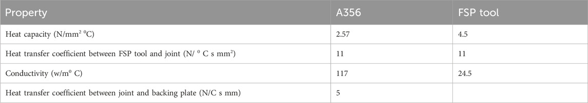
Table 3. Thermal properties of aluminium alloy and H13 FSP tool (Akbari et al., 2023).
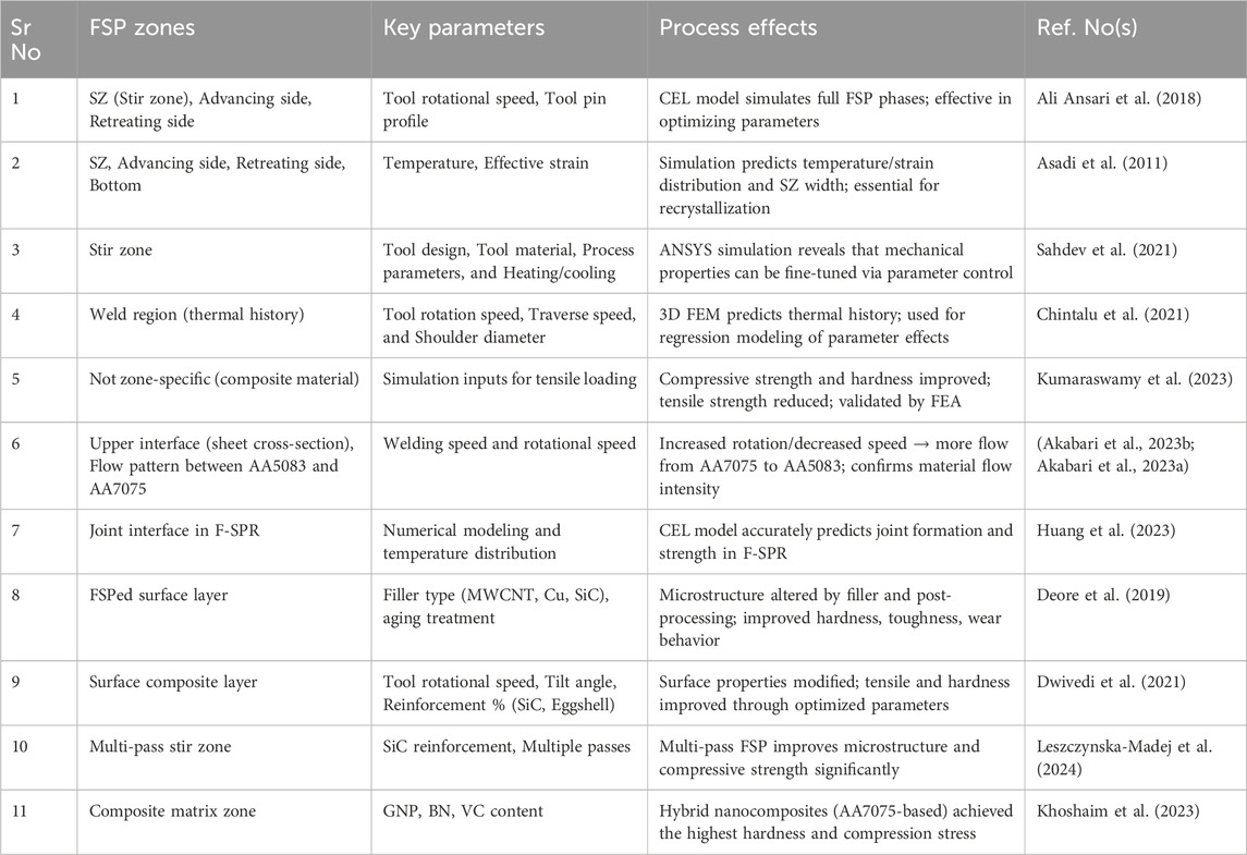
Table 4. Comparative study of friction stir processing techniques and their effects.
Menda et al. (2024) recommended aluminum composites to meet the growing demand for hybrid materials that need to be produced more quickly. Because of its excellent corrosion resistance, low weight, and high heat resistance, this composite material finds extensive use in the automotive and aerospace industries. The primary objective of this project was to produce graphene and TiB2 reinforcements for the Al7075 alloy. Using the stir casting technique, mechanical and tribological properties were measured and improved by mixing TiB2 and graphene with the foundation material, aluminum-7075. While the TiB2 content ranged from 1% to 15% of its total weight, the recommended graphene content was 1%, 2%, and 3%.
7 Effect of FSW on microstructures
B. Mohan Bharathi et al. explores the enhancement of AZ31 magnesium alloy through friction stir processing (FSP) followed by heat treatment improves the corrosion resistance as shown in Figures 9, 10 (Mohan Bharathi et al., 2020).
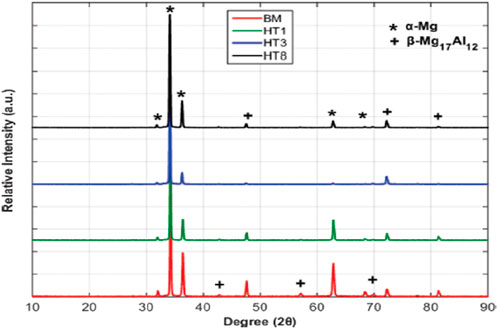
Figure 9. Constitutional phases in BM, HT1, HT3, and HT8 (XRD) (Mohan Bharathi et al., 2020).
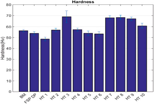
Figure 10. Microhardness of the specimens (Mohan Bharathi et al., 2020).
Using a 3D FEM model, M. Akabari et al. examined how tool components contribute to heat and strain development during friction stir welding (FSW) as shown in Figures 11, 12. The results show that the tool shoulder generates 90% of the heat, with the probe alone contributing very little. Frictional heat is the main cause of the workpiece’s rising temperature, as opposed to plastic deformation shown in Figures 13–15. Important information for improving the design of FSW/FSP tools to increase welding efficiency is provided by this study (Akbari et al., 2023; Ali Ansari et al., 2018; Geng et al., 2022).
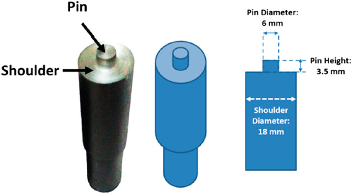
Figure 11. Dimensions of the tool (Akbari et al., 2023).
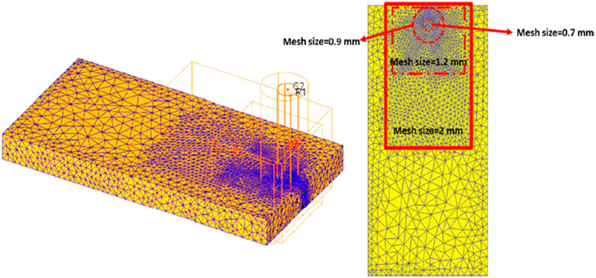
Figure 12. Meshing of the workpiece (Akbari et al., 2023).
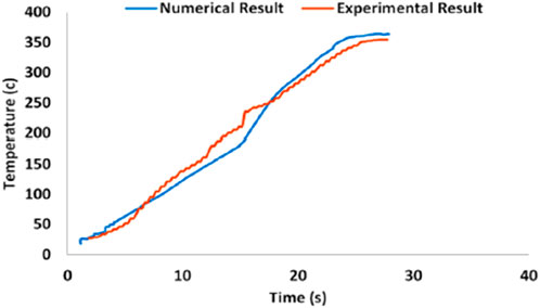
Figure 13. Temperature history from experimental tests (Akbari et al., 2023).
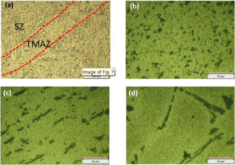
Figure 14. Microstructure of (a) the welding zone; (b) the SZ; (c) the TMAZ; (d) the parent alloy (Akbari et al., 2023).
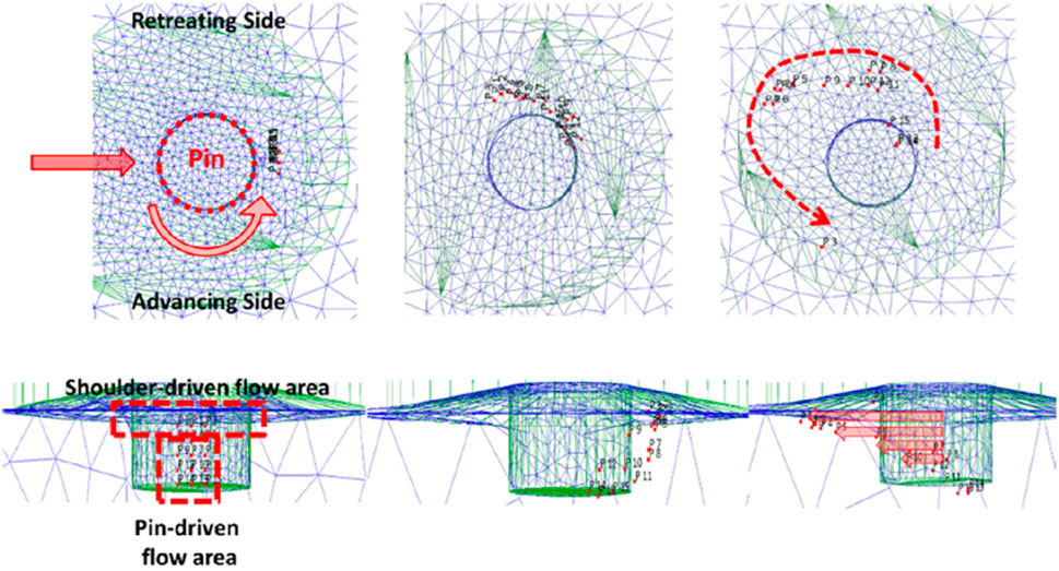
Figure 15. Material flow pattern (Akbari et al., 2023).
Mohammad Ali Ansari et al. proposed a computationally efficient model for friction stir processing using ABAQUS/explicit with a coupled Eulerian–Lagrangian (CEL) approach as shown in Figures 16–18. Their model simulated the 3D finite element, tool plunge, dwelling, and stirring stages in the FSP of aluminum alloy 5083. Through experimental force and temperature measurements, simulations examine the impacts of pin profile and tool rotating speed shown in Figure 19. The article emphasizes how the CEL model may optimize FSP parameters for industrial applications and capture intricate process dynamics. In this work, a three-dimensional CEL model was developed and solved using ABAQUS/Explicit to imitate the FSP process’s plunging, dwelling, and stirring phases. Although a Lagrangian formulation was used to describe the FSP tool, the model treated the workpiece as an Eulerian domain (Ulysse, 2002b; Al-Badour et al., 2013; Salloomi and Al-Sumaidae, 2021; Chauhan et al., 2018; Das et al., 2021; Ducobu et al., 2017). The Eulerian domain size was taken into consideration in accordance with the stress-free inflow condition because of the low computing efficiency and localized deformation during the FSP process. Accuracy and computational cost were traded off when choosing the domain size as shown in Figures 20, 21 (Ali Ansari et al., 2018).
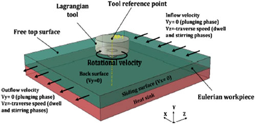
Figure 16. CEL model boundary conditions (Ali Ansari et al., 2018).
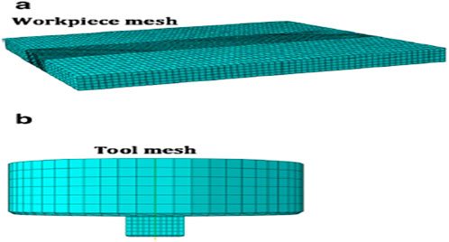
Figure 17. Mesh of the CEL model’s (a) workpiece Eulerian mesh and (b) tool Lagrangian mesh (Ali Ansari et al., 2018).
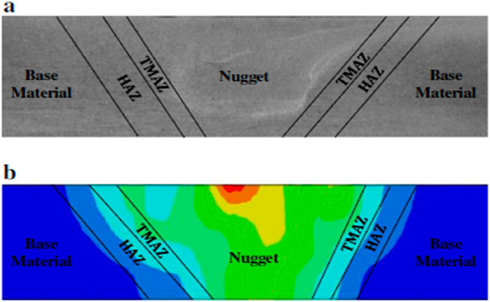
Figure 18. Comparison of the (a) cross-section of a stirred zone and (b) simulated plastic strain (Ali Ansari et al., 2018).
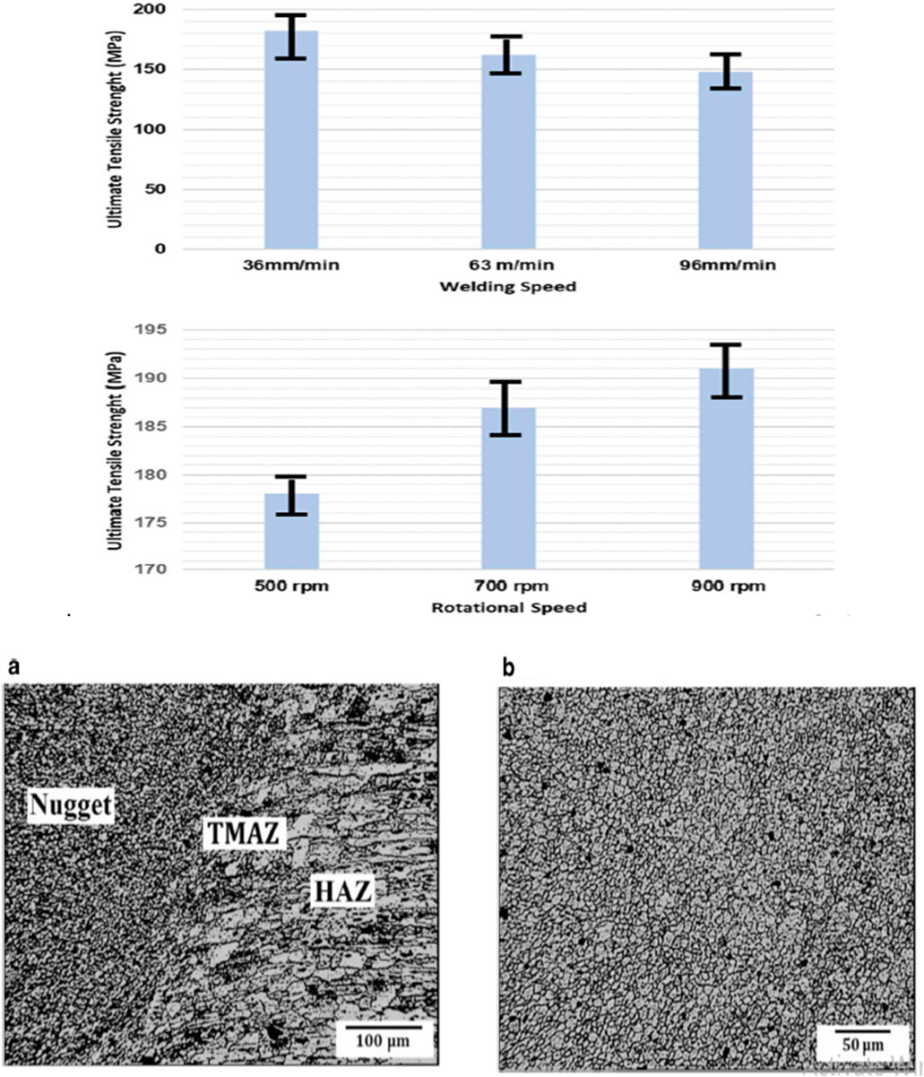
Figure 19. UTS variation against welding and rotational speed (Akabari et al., 2023b). (a) Transition zone. (b) Nugget optical micrograph (Ali Ansari et al., 2018).
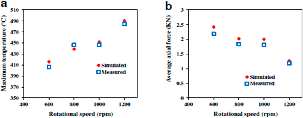
Figure 20. Impact of tool rotation speed on the average axial force during the stirring phase and the maximum temperature from the centerline (Ali Ansari et al., 2018).
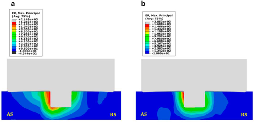
Figure 21. The equivalent plastic strain rate distribution is found for rotational speeds of (a) 600 rpm and (b) 800 rpm (Ali Ansari et al., 2018).
Equations 1–3 (Benson and Okazawa, 2004) demonstrate how the Eulerian formulation, which conserves mass, momentum, and energy, was used to model the workpiece domain in the CEL model created in this study. The mass outflow rate and the rate of mass change inside the control volume are handled by the mass conservation equation. The change of the domain’s momentum is equal to the sum of the body force and the spatial time derivative of the Cauchy stress tensor, according to the momentum conservation equation. The rate of work done on any element, the heat flux into the element through conduction, and the volumetric heat generation from the element are all included in the energy equation.
Where
Where
David J. Benson et al. discussed multi-material Eulerian and Lagrangian formulations in solid mechanics. In Eulerian models, adjacent materials are perfectly bonded, while Lagrangian models require contact algorithms to enforce interaction constraints. Advanced contact algorithms are widely used in Lagrangian methods for large deformation problems like crash simulations, whereas Eulerian methods lag in contact modeling. An Eulerian formulation is well-suited for machining simulations, involving large deformations, material failure, and tool–workpiece contact. Simulating isolated chips with shear band failure is used to assess contact implementation in multi-material Eulerian models as shown in Figures 22, 23 (Benson and Okazawa, 2004).
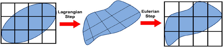
Figure 22. The operator split for a Eulerian formulation (Benson and Okazawa, 2004).
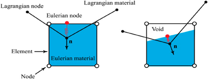
Figure 23. The definitions of the penetration for pure and void elements (Benson and Okazawa, 2004).
Deore H.A. et al. successfully produced AA 7075-based surface composites with MWCNT, Cu, and SiC fillers using friction stir processing, attaining uniform dispersion shown in Figure 24. Microstructural characterization was carried out utilizing OM, SEM, EBSD, and XRD. Wear tests, impact toughness tests, and hardness tests were used to analyze mechanical properties. Following FSP and age hardening, the microhardness of SiC-reinforced composites increased from 143 HV0.1 to 253 HV0.1, indicating the greatest improvement. Wear loss decreased from 8.57 mg to 5.49 mg, and impact toughness increased from 15.8 kJ to 27.5 kJ. Precipitate evolution, Zener pinning, and grain refining were credited with the improvements. The best filler under the specified FSP and age-hardening conditions was SiC. Age-hardened SiC composites were used to produce nearly a two-fold improvement in hardness, as well as improvements in toughness and wear resistance shown in Figure 25 (Saeidi et al., 2015; Lebaal et al., 2017; Elangovan et al., 2009; Adetunla and Akinlabi, 2020; Harwani et al., 2023; Deore et al., 2019; Deore et al., 2022).
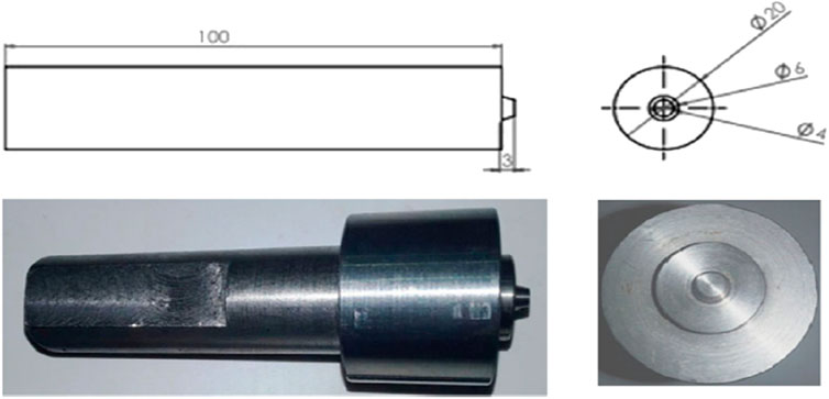
Figure 24. W-La2O instrument utilized for the experiment’s actual photograph and drawing (Deore et al., 2019).
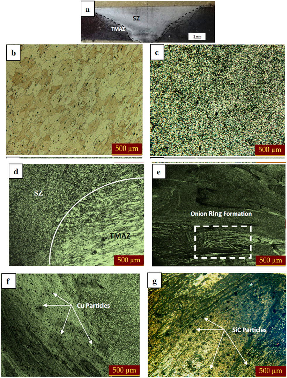
Figure 25. (a) Microstructure after FSP; (b) base metal AA7075 T6; (c) FSPed AA7075 stir zone without filler; (d) transition between FSPed stir zone and thermomechanically affected zone; (e) FSPed AA7075 stir zone with MWCNT filler; (f) FSPed AA7075 stir zone with Cu filler; (g) one of the FSPed AA7075s with SiC filler displayed in optical microstructures (Deore et al., 2019).
Equations have been developed to model heat input from various FSP tool geometries and were validated using thermocouple data shown in Figure 26 (Deore et al., 2021; Wu et al., 2014; Gopan et al., 2018; Hofmann and Vecchio, 2007; Cavaliere and Squillace, 2005). Cooling curves were applied to the Derby–Ashby model to predict the final grain size. Submerged friction stir processing (SFSP) was introduced to increase cooling rates and refine grain structure. Microstructures from FSP and SFSP were analyzed using transmission electron microscopy (Hasan Shojaeefard et al., 2015; Senthilkumar et al., 2019).
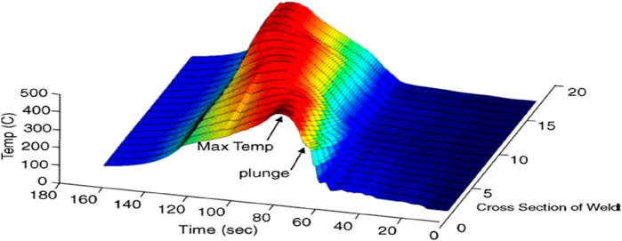
Figure 26. 3D plot of FSW across the weld surface (Hofmann and Vecchio, 2007).
8 Conclusion
The study conducted on friction stir processing (FSP) for AA7075 to enhance its mechanical characteristics, including strength, hardness, and fatigue resistance. The uses of AA7075 in the structural, automotive, and aerospace industries are examined in addition to a comparative study of several light metal alloys. The effects of many FSP parameters on tool life, processing cost, joint quality, and overall process efficiency are investigated. The traverse speed, tilt angle, plunge depth, and tool rotation speed are some of these variables. The tool’s material selection has a significant impact on the thermomechanical properties and material flow behavior during processing. Different tool-workpiece combinations are evaluated to identify the optimal options based on the operating temperature range and material compatibility.
The effect of FSP on microstructural evolution in different zones, including the stir zone, the thermomechanically affected zone (TMAZ), and the heat-affected zone (HAZ), is analyzed. The influence of grain refinement and precipitation hardening due to FSP is explored to understand property enhancements. The study also highlights advancements in process optimization, including multi-pass FSP and hybrid processing techniques. Additionally, challenges such as tool wear, defect formation, and heat management are addressed. Overall, the review provides insights into improving the efficiency and effectiveness of FSP for AA7075 through process modifications and material selection.
For FSP, a thermomechanical 3D FE model with CEL formulation was effectively created to model the process reaction. The three FSP steps— plunging, dwelling, and stirring—are replicated in ABAQUS/Explicit. The mass scaling technique is used to increase the efficiency of the computation. Both the retreating and advancing sides’ simulated temperature profiles matched the experiments quite well. Experimental validation is also performed on the contour plot and simulated force profile of a comparable plastic strain of the cross-section of the workpiece. The force profiles, strain rate, and process temperature during friction stir processing were all significantly impacted by the tool rotational speed, according to the simulation. The peak temperature in the stirring zone rose as the tool pin surface increased because of the increased frictional heat produced by the increasing frictional surface interaction between the tool and the work material. Temperature, strain, and material flow are evaluated during the FSP of AA7075 using a coupled Eulerian–Lagrangian model.
Author contributions
TP: Conceptualization, Software, Investigation, Resources, Supervision, Funding acquisition, Writing – original draft, Project administration, Validation, Writing – review and editing, Visualization, Data curation, Methodology, Formal Analysis. DW: Visualization, Data curation, Formal Analysis, Validation, Project administration, Resources, Methodology, Writing – review and editing, Software, Investigation, Writing – original draft, Conceptualization, Funding acquisition, Supervision. AP: Writing – review and editing, Funding acquisition, Supervision, Investigation, Writing – original draft, Software, Data curation, Validation, Resources, Project administration, Conceptualization, Methodology, Visualization, Formal Analysis. MN: Writing – original draft, Writing – review and editing. SSh: Writing – review and editing, Writing – original draft. SSa: Writing – original draft, Formal Analysis, Project administration, Validation, Data curation, Visualization, Resources, Supervision, Conceptualization, Writing – review and editing, Investigation, Software, Funding acquisition, Methodology.
Funding
The author(s) declare that no financial support was received for the research and/or publication of this article.
Conflict of interest
The authors declare that the research was conducted in the absence of any commercial or financial relationships that could be construed as a potential conflict of interest.
Generative AI statement
The author(s) declare that no Generative AI was used in the creation of this manuscript.
Any alternative text (alt text) provided alongside figures in this article has been generated by Frontiers with the support of artificial intelligence and reasonable efforts have been made to ensure accuracy, including review by the authors wherever possible. If you identify any issues, please contact us.
Publisher’s note
All claims expressed in this article are solely those of the authors and do not necessarily represent those of their affiliated organizations, or those of the publisher, the editors and the reviewers. Any product that may be evaluated in this article, or claim that may be made by its manufacturer, is not guaranteed or endorsed by the publisher.
References
Aalco (2021). Introduction to aluminium and its alloys. Available online at: http://www.aalco.co.uk/datasheets/Aluminium-Alloy_Introduction-to-Aluminium-and-its-alloys_9.ashx (Accessed September 10, 2024).
Abbasi, M., Abdollahzadeh, A., Bagheri, B., Moghaddam, A. ostovari, Sharifi, F., and Dadaei, M. (2021). Study on the effect of the welding environment on the dynamic recrystallization phenomenon and residual stresses during the friction stir welding process of aluminum alloy. J. Mater. Des. Appliations 235, 1809–1826. doi:10.1177/14644207211025113
Adetunla, A., and Akinlabi, E. (2020). “Finite element analysis of the heat generated during FSP of 1100 Al alloy,” in Advances in manufacturing engineering. doi:10.1007/978-981-15-5753-8_39
Akabari, M., Asadi, P., and Sadowski, T., (2023a). A review on friction stir welding: numerical modelling. doi:10.20944/preprints202307.1296.v1
Akabari, M., Asiabaraki, H. R., and Aliha, M. R. M. (2023b). Investigating of the effect of welding and rotational speed on strain and temperature during friction stir welding of AA5083 and AA7075 using the CEL approach. Eng. Res. Express 5. doi:10.1088/2631-8695/acca00
Akbari, M., Aliha, M. R. M., and Berto, F. (2023). Investigating the role of different components of friction stir welding tools on the generated heat and strain. Forces Mech. 10, 100166. doi:10.1016/j.finmec.2023.100166
Al-Badour, F., Merah, N., Shuaib, A., and Bazoune, A. (2013). Coupled Eulerian lagrangian finite element modeling of friction stir welding processes. J. Mater. Process. Technol. 213, 1433–1439. doi:10.1016/j.jmatprotec.2013.02.014
Ali Ansari, M., Samanta, A., Abdi Behnagh, R., and Ding, H. (2018). An efficient coupled Eulerian-Lagrangian finite element model for friction stir processing. Int. J. Adv. Manuf. Technol. 101, 1495–1508. doi:10.1007/s00170-018-3000-z
Arbegast, J. W. (2003). A flow partitioned deformation zone model for defect formation during friction stir welding. Hot Deformation Alum. Alloys III, 372–376. doi:10.1016/j.scriptamat.2007.10.031
Asadi, P., Mahadavinejad, R. A., and Tutunchilar, S. (2011). Simulation and experimental investigation of FSP of AZ91 magnesium alloy. Mater. Sci. Eng. A 528, 6469–6477. doi:10.1016/j.msea.2011.05.035
Bagherpour, E., Pardis, N., Reihanian, M., and Ebrahimi, R. (2019). An overview on severe plastic deformation: research status, techniques classification, microstructure evolution, and applications. Int. J. Adv. Manuf. Tech. 100, 1647–1694. doi:10.1007/s00170-018-2652-z
Benson, D. J. (1997). A mixture theory for contact in multi-material Eulerian formulations. Comput. methods Appl. mehanics Eng. 140, 59–86. doi:10.1016/s0045-7825(96)01050-x
Benson, D. J. (2000). An implicit multi-material Eulerian formulation. Int. J. Numer. Methods Eng. 48, 475–499. doi:10.1002/(sici)1097-0207(20000610)48:4<475::aid-nme881>3.0.co;2-u
Benson, D. J., and Okazawa, S. (2004). Contact in a multi-material Eulerian finite element formulation. Comput. methods Appl. Mech. Eng. 193, 4277–4298. doi:10.1016/j.cma.2003.12.061
Benson, D. J., and Stainier, L. (2000). An Eulerian shell formulation for fluid-structure interaction. Comput. methods Appl. mehanics Eng. 187, 571–590. doi:10.1016/s0045-7825(99)00340-0
Besharati-Givi, M. K., and Asadi, P. (2014). “Advances in friction stir welding and processing,” in Kidlington. Cambridge, United Kingdom: Woodhead Publishing.
Bhojak, V., Jain, J. K., Saxena, K.Kr, Singh, B., and Mohammed, K. A. (2023). Friction stir process: a comprehensive review on material and methodology. Indian J. Eng. and Material Sci. 30, 45–64. doi:10.56042/ijems.v1i1.61877
Bhovi, P. M., Patil, D. C., Kori, S. A., Venkateswarlu, K., Huang, Y., and Langdon, T. G. (2016). A comparison of repetitive corrugation and straightening and high-pressure torsion using an al-mg-sc alloy. J. Mater. Res. Technol. 5 (4), 353–359. doi:10.1016/j.jmrt.2016.03.009
Cavaliere, P., and Squillace, A. (2005). High temperature deformation of friction stir processed 7075 aluminium alloy. Mater. Charact. 55, 136–142. doi:10.1016/j.matchar.2005.04.007
Charit, I., and Mishra, R. S. (2005). Low temperature superplasticity in a friction-stir-processed ultrafine grained al-zn-mg-sc alloy. Acta Mater 53 (15), 4211–4223. doi:10.1016/j.actamat.2005.05.021
Chauhan, P., Jain, R., Pal, S. k., and Singh, S. B. (2018). Modeling of defects in friction stir welding using coupled Eulerian and Lagrangian method. J. Manuf. Process. 34, 158–166. doi:10.1016/j.jmapro.2018.05.022
Chawla, S. L., and Gupta, R. K. (1993). Materials selection for corrosion control. Materials Park, Ohio: ASM International.
Chen, K., Liu, X., and Ni, J. (2016). Thermal-mechanical modeling on friction stir spot welding of dissimilar materials based on coupled eulerian-lagrangian approach. Int. J. Adv. Manuf. Technol. 91, 1697–1707. doi:10.1007/s00170-016-9884-6
Chintalu, R. S., Padmanaban, R., and Vignesh, R. V. (2021). Finite element modelling of thermal history during friction stir processing of AA5052. Mater. Today Proc. 5 January 46, 7452–7458. doi:10.1016/j.matpr.2021.01.105
Das, D., Bag, S., and Pal, S. (2021). A finite element model for surface and volumetric defects in the FSW process using a coupled Eulerian–Lagrangian approach. Sci. and Technol. Weld. and Join. 26, 412–419. doi:10.1080/13621718.2021.1931760
J. R. Davis (1993). Aluminum and aluminum alloys, ASM specialty handbook (Materials Park, OH: ASM International), 3–12.
Deore, H. A., Asadi, J., Rao, A. G., Mehtani, H., and Hiwarkar, V. D. (2019). Effect of filler material and post process ageing treatment on microstructure, mechanical properties and wear behaviour of friction stir processed AA7075 surface composites. Surf. Coat. Tech. 374, 52–64. doi:10.1016/j.surfcoat.2019.05.048
Deore, H. A., Nichul, U., Rao, A. G., and Hiwarkar, V. D. (2021). Microstructural investigation of WC reinforced Ti-6Al-4V matrix surface composite fabricated via additive friction stir processing. Materialia 20, 101235. doi:10.1016/j.mtla.2021.101235
Deore, H. A., Nichul, U., Rao, A. G., and Hiwarkar, V. D. (2022). Influence of SiC particles and post-heat treatment on the properties of Ti-6Al-4V-based surface nanocomposite fabricated by friction stir processing. Surf. and Coat. Technol. 449, 128985. doi:10.1016/j.surfcoat.2022.128985
Dias, F., cipriano, G., Correia, A. N., Braga, D. F. O., Moreira, P., and infant, V. (2023). Joining of aluminum alloy AA7075 and titanium alloy Ti-6Al-4V through a friction stir welding-based process. Met. MDPI 13, 249. doi:10.3390/met13020249
Dorum, C., Laukli, H. I., Hopperstad, O. S., and Langseth, M. (2009). Through process numerical simulations of the structural behaviour of Al-Si die-castings. Eur. J. Mech. A Solids 28, 100–111. doi:10.1016/j.commatsci.2008.12.022
Ducobu, F., Arrazola, P.-J., Riviere-Lorphevre, E., Ortiz de Zarate, G., Madariaga, A., and Fillippi, E. (2017). The CEL method as an alternative to the current modelling approaches for Ti6Al4V orthogonal cutting simulation. Procedia CIRP 58, 245–250. doi:10.1016/j.procir.2017.03.188
Dwivedi, R., Singh, R. K., Kumar, S., and Srivastava, A. K. (2021). Parametric optimization of process parameters during the friction stir processing of Al7075/SiC/Waste eggshell surface composite. Mater. Today Proc. 47, 3884–3890. doi:10.1016/j.matpr.2021.03.545
Edwards, D. P., and Crouch, I. G. (2017). “Light alloys,” in The Science of Armour Materials. Cambridge, United Kingdom: Woodhead Publishing. 117–166.
Edwards, G. A., Stiller, K., Dunlop, G. L., and Couper, M. J. (1998). The precipitation sequence in al-mg-si alloys. Acta Mater 46 (11), 3893–3904. doi:10.1016/S1359-6454(98)00059-7
Elangovan, K., Balasubramanian, V., and Babu, S. (2009). Predicting tensile strength of friction stir welded AA6061 aluminium alloy joints by a mathematical model. Mater. Des. 30, 188–193. doi:10.1016/j.matdes.2008.04.037
Fernandez, P., Gonzalez, G., Alfonso, I., and Figueroa, I. (2010). Hardness-lattice parameter correlation for aged al-zn-mg alloys. J. Mater. Process. Technol. 26, 1083–1088. doi:10.1016/S1005-0302(11)60005-4
Geng, P., Ma, Y., Ma, H., Aoki, Y., and Liu, H. (2022). Effects of rotation tool-induced heat and material flow behaviour on friction stir lapped Al/steel joint formation and resultant microstructure. Int. J. Mach. Tools Manuf. 174, 103858. doi:10.1016/j.ijmachtools.2022.103858
Gopan, V., Sreekumar, P. S., Chandran, J. p, Vijay, W., and Sanjay Kumar, M. (2018). Experimental investigation on the effect of process parameters on friction stir processing of aluminium. Mater. Today Proc. 5, 13674–13681. doi:10.1016/j.matpr.2018.01.139
Goyal, A., and Garg, R. K. (2019). Modelling and optimization of friction stir welding parameters in joining 5086 H32 aluminium alloy. Sci. Iran. 26, 2407–2417. doi:10.24200/sci.2018.5525.1325
Grujicic, M., Arakere, G., Yalavarthy, H. V., He, T., Yen, C.-F., and Cheeseman, B. A. (2010). Fully coupled thermomechanical finite element analysis of material evolution during friction stir welding of AA5083. J.Mater. Eng. Perform. 19, 609–625. doi:10.1243/09544054JEM1750
Harwani, D., Badheka, V., and Patel, V. (2023). High temperature tensile deformation in single-pass friction stirred AZ31 alloy. Int. J. lightweight Mater. Manuf. 6, 140–148. doi:10.1016/j.ijlmm.2022.09.003
Hasan Shojaeefard, M., khalkhali, A., Akabari, M., and Asadi, P. (2015). Investigation of friction stir welding tool parameters using FEM and neural network. Journals Mater. Des. Appl. 229, 209–217. doi:10.1177/1464420713509075
J. E. Hatch (1984). Aluminum properties and physical metallurgy (Materials Park, OH: American Society for Metals), 5–183. doi:10.1361/appm1984p001
Heurtier, P., Desrayaud, C., and Montheillet, F. (2002). A thermomechanical analysis of the friction stir welding process. Mater. Sci. Forum 96-402, 1537–1542. doi:10.4028/www.scientific.net/MSF.396-402.1537
Hofmann, D. C., and Vecchio, K. S. (2007). Thermal history analysis of friction stir processed and submerged friction stir processed aluminum. Mater. Sci. Eng. 465, 165–175. doi:10.1016/j.msea.2007.02.056
Hong, M., Wu, D., Chen, R. S., and Du, X. H. (2014). Ductility enhancement of EW75 alloy by multi-directional forging. J. Magnes. Alloy 2, 317–324. doi:10.1016/j.jma.2014.11.005
Huang, H., Lim, Y. C., Wang, Y., Yuan, Li, and Feng, Z. (2023). Crack free joining of high strength AA7055 sheets by friction based self-piercing riveting with the aid of numerical design. J. Manuf. Material Process. 7, 216. doi:10.3390/jmmp7060216
Kesharwani, R., Jha, K., Imam, M., Sarkar, C., and Barsoum, I. (2024). Correlation of microstructure, texture, and mechanical properties of friction stir welded joints of AA7075-T6 plates using a flat tool pin profile. Heliyon 10 (3), e25449. doi:10.1016/j.heliyon.2024.e25449
Khoshaim, A. B., Moustafa, E. B., Alazwari, M. A., and Taha, M. A. (2023). An investigation of the mechanical, thermal and electrical properties of an AA7075 alloy reinforced with hybrid ceramic nanoparticles using friction stir processing. Metals 13, 124. doi:10.3390/met13010124
Kumaraswamy, J., Anil, K. C., Veena, T. R., Purushotham, G., and Sunil Kumar, K. (2023). Investigating the mechanical properties of Al7075 alloy for automotive applications: synthesis and analysis. Evergr. Jt. J. Nov. Carbon Resour. Sci. and Green Asia Strategy 10 (03), 1286–1295. doi:10.5109/7151674
Lebaal, N., Chamoret, D., Schlegel, D., and Folea, M. (2017). Thermal modelling of friction stir process and identification parameters. Material Phys. Mech. 32, 14–20.
Leszczynska-Madej, B., Madj, M., Wasik, A., and Weglowska, A. (2024). Microstructural homogenization and mechanical enhancement of aluminum matrix composites via multi-pass friction stir processing with SiC reinforcements. Int. J. Adv. Technol. 134, 2035–2050. doi:10.1007/s00170-024-14252-w
Lin, J. C., Liao, H. L., Jehng, W. D., Chang, C. H., and Lee, S. L. (2006). Effect of heat treatments on the tensile strength and SCC-resistance of AA7050 in an alkaline saline solution. Corros. Sci. 48 (10), 3139–3156. doi:10.1016/j.corsci.2005.11.009
Liu, P., Hu, J.-Y., Li, H.-X., Sun, S.-Y., and Zhang, Y.-B. (2020). Effect of heat treatment on microstructure, hardness and corrosion resistance of 7075 Al alloys fabricated by SLM. J. Manuf. Process. 60, 578–585. doi:10.1016/j.jmapro.2020.10.071
Lockwood, W. D., and Reynolds, A. P. (2002). Simulation of the global response of a friction stir weld using local constitutive behavior. Mater. Sci. Eng. A 339, 35–42. doi:10.1016/S0921-5093(02)00116-8
Lockwood, W. D., Tomaz, B., and Reynolds, A. P. (2002). Mechanical response of friction stir welded AA2024: experiment and modeling. Mater. Sci. Eng. A 323, 348–353. doi:10.1016/S0921-5093(01)01385-5
Mackerle, J. (1999). Finite-element analysis and simulation of machining: a bibliography. J. Mater. Process. Tehnology 86, 17–44. doi:10.1016/s0924-0136(98)00227-1
Menda, V., Dora, S., Palli, S., Raju Rallabandi, S., Sharma, R. C., Sharma, N., et al. (2024). Mechanical and wear characteristics of Aluminium-7075/graphene/TiB2 prepared by stir casting. Engg. Res. Express 6, 025571. doi:10.1088/2631-8695/ad58a8
Mishra, R. S. (2004). Evaluation of microstructure and superplasticity in friction stir processed 5083 Al alloy. J. Mater. Res. 19 (11), 3329–3342. doi:10.1557/JMR.2004.0429
Mishra, R. S., and Ma, Z. Y. (2005). Friction stir welding and processing. Mater. Sci. Eng. R. 50, 1–78. doi:10.1016/j.mser.2005.07.001
Mishra, R. S., Mahoney, M. W., McFadden, S. X., Mara, N., and Mukherjee, A. (2000). High strain rate superplasticity in a friction stir processed 7075 Al alloy. Scr Mater 42 (2), 163–168. doi:10.1016/S1359-6462(99)00329-2
Mohan Bharathi, B., Vaira Vignesh, R., Padmanaban, R., and Govindaraju, M. (2020). Effect of friction stir processing and heat treatment on the corrosion properties of AZ31 alloy. Aust. J. Mech. Eng. 20, 1479–1488. doi:10.1080/14484846.2020.1815999
W. A. Monteiro (2014). Light metal alloys applications (London, United Kingdom: Intech Open publication), 1–35.
Mukhopadhyay, A. K. (2010). Microstructure and properties of high strength aluminum alloys for structural applications. Scr Mater 1, 99. doi:10.1016/j.scriptamat.2010.10.038
Mukhopadhyay, A. K. (2012a). Selection and design principles of wrought aluminium alloys for structural applications. Mater. Sci. Forum 710, 50–65. doi:10.4028/www.scientific.net/MSF.710.50
Mukhopadhyay, A. K. (2012b). Comparative study of indentation size effects in as-sintered alumina and alumina shock deformed at 6.5 and 12 gpa. ISRN Metallurgy, 1–15. doi:10.5402/2012/595172
Pan, L., Liu, K., Breton, F., and -Grant Chen, X. (2016). Effect of Fe on microstructure and properties of 8xxx aluminum conductor alloys. J. Mater. Eng. Perform. 25, 5201–5208. doi:10.1007/s11665-016-2373-0
Pawar, A., Kamble, D., and Jadhav, D. B. (2024). Experimental investigation on titanium alloys for machining of stepped circular holes using ultrasonic-assisted hybrid ECM. J. Eng. Appl. Sci. 71 (1), Pg-58. doi:10.1186/s44147-024-00395-w
Rai, R., De, A., Bhadeshia, H. K., and Roy, T. D. (2011). Review: friction stir welding tools. Sci. Technol. Weld. Join. 16 (4), 325–342. doi:10.1179/1362171811Y.0000000023
Robson, J. D. (2004). Microstructural evolution in aluminium alloy 7050 during processing. Mater. Sci. Eng. A 382, 112–121. doi:10.1016/j.msea.2004.05.006
Saeidi, M., Manafi, B., Givi, M. K. B., and Faraji, G. (2015). Mathematical modelling and optimization of friction stir welding process parameters in AA5083 and AA7075 aluminum alloy joints. J. Eng. Manuf. doi:10.1177/0954405415573697
Sahdev, S., Kumar, H., Butola, R., and Singari, R. M. (2021). Evaluating the effect of process parameters on FSP of Al5083 alloy using ANSYS. J. Inf. Sci. Technol. Assoc. 45 (2), 113–120. doi:10.18280/acsm.450203
Salloomi, K. N., and Al-Sumaidae, S. (2021). Coupled eulerian–lagrangian prediction of thermal and residual stress environments in dissimilar friction stir welding of aluminum alloys. J. Adv. Join. Process. 3, 100052. doi:10.1016/j.jajp.2021.100052
Senthilkumar, R., Prakash, M., Arun, N., and Arul Jeyakumar, A. (2019). The effect of the number of passes in friction stir processing of aluminum alloy (AA6082) and its failure analysis. Appl. Surf. Sci. 491, 420–431. doi:10.1016/j.apsusc.2019.06.132
Sharma, N., Siddiquee, A. N., Khan, Z. A., and Mohammed, M. T. (2018). Analysis of process parameters effects on underwater friction stir welding of aluminum alloy 6082-T6. Mater Manuf. Process, 786–794. doi:10.1177/0954405418789982
Simar, A., Bréchet, Y., De Meester, B., Denquin, A., Gallais, C., and Pardoen, T. (2012). Integrated modelling of friction stir welding of 6xxx series Al alloy: process, microstructure and properties. Prog. Mater. Sci. 57, 95–183. doi:10.1016/j.pmatsci.2011.05.003
Skinner, M., and Edwards, R. L. (2003). Improvements to the FSW process using the self-reacting technology. Mater. Sci. Forum 426-432, 2849–2854. doi:10.4028/www.scientific.net/MSF.426-432.2849
Song, M., and Kovacevic, R. (2003). Thermal modeling of friction stir welding in a moving coordinate system and its validation. Int. J. Mach. Tools Manuf. 43, 605–615. doi:10.1016/S0890-6955(03)00022-1
Tozaki, Y., Uematsu, Y., and Tokaji, K. (2010). A newly developed tool without probe for friction stir spot welding and its performance. J. Mater. Process. Technol. 210, 844–851. doi:10.1016/j.jmatprotec.2010.01.015
Toroghinejad, M. R., Ashrafizadeh, F., and Jamaati, R. (2013). On the use of accumulative roll bonding process to develop nanostructured aluminum alloy 5083. Mater. Sci. Eng. A 561, 145–151. doi:10.1016/j.msea.2012.11.010
Totik, Y., Sadeler, R., Kaymaz, I., and Gavgali, M. (2004). The effect of homogenisation treatment on cold deformations of AA2014 and AA6063 alloys. J. Mater. Process. Technol. 147, 60–64. doi:10.1016/j.jmatprotec.2003.10.026
Ulysse, P. (2002a). Three-dimensional modeling of the friction stir-welding process. Int. J. Mach. Tools Manuf. 42, 1549–1557. doi:10.1016/S0890-6955(02)00114-1
Ulysse, P. (2002b). Three-dimensional modeling of the friction stir-welding process. Int. J. Mach. Tools and Manuf. 42, 1549–1557. doi:10.1016/s0890-6955(02)00114-1
Vailey, R. Z., Islamgaliev, R. K., and Alexandrov, I. (2000). Bulk nanostructured materials from severe plastic deformation. Prog. Mater. Sci. 45 (2), 103–189. doi:10.1016/S0079-6425(99)00007-9
Vaira Vignesh, R., padmanaban, R., Arivarasu, M., Thirumalini, S., Gokulahandran, J., and Ram, M. S. S. S. (2016). Numerical modelling of thermal phenomenon in friction stir welding of aluminum plates. IOP Conf. Ser. Material Sci. Eng. 149, 012208. doi:10.1088/1757-899X/149/1/012208
Valiev, R. Z., and Langdon, T. G. (2006). Principles of equal-channel angular pressing as a processing tool for grain refinement. Prog. Mater. Sci. 51 (7), 881–981. doi:10.1016/j.pmatsci.2006.02.003
Valiev, R., Estrin, Y., Horita, Z., Langdon, T., Zehetbauer, M., and Zhu, Y. (2016). Fundamentals of superior properties in bulk NanoSPD materials. Mater. Res. Lett. 4 (1), 1–21. doi:10.1080/21663831.2015.1060543
Wang, S. C., Starink, M. J., and Gao, N. (2006). Precipitation hardening in al-cu-mg alloys revisited. Scr Mater 54 (2), 287–291. doi:10.1016/j.scriptamat.2005.09.010
Wang, D., Ni, D., and Ma, Z. (2008). Effect of pre-strain and two-step aging on microstructure and stress corrosion cracking of 7050 alloy. Mater. Sci. Eng. A 494, 360–366. doi:10.1016/j.msea.2008.04.023
Wang, L. J., Xu, D. K., Rometsch, P. A., Gao, S. X., Zhang, Y., He, Z. B., et al. (2011). Effect of homogenisation parameters on dissolution and precipitation in aluminium alloy AA7150. Mater. Sci. Forum 693, 276–281. doi:10.4028/www.scientific.net/MSF.693.276
Wei, Q., Cheng, S., Ramesh, K. T., and Ma, E. (2004). Effect of nanocrystalline and ultrafine grain sizes on the strain rate sensitivity and activation volume: FCC versus BCC metals. Mater. Sci. Eng. A 381 (1-2), 71–79. doi:10.1016/j.msea.2004.03.064
Wu, L. H., Wang, D., Xiao, B. L., and Ma, Z. Y. (2014). Tool wear and its effect on microstructure and properties of friction stir processed Ti-6Al-4V. Material Chem. Phys. 146, 512–522. doi:10.1016/j.matchemphys.2014.04.002
Xu, X., Zheng, J., Li, Z., Luo, R., and Chen, B. (2017). Precipitation in an al-zn-mg-cu alloy during isothermal aging: Atomic Scale HAADF-STEM investigation. Mater. Sci. Eng. A 691, 60–70. doi:10.1016/j.msea.2017.03.032
Zendehdel, H., and Hassani, A. (2012). Influence of twist extrusion process on microstructure and mechanical properties of 6063 aluminum alloy. Mater. Des. 37, 13–18. doi:10.1016/j.matdes.2011.12.009
Keywords: lightweight materials, friction stir process, coupled Eulerian–Lagrangian, AA7075 alloy, Abaqus
Citation: Patil T, Washimkar D, Pawar A, Naidu M, Shinde S and Salunkhe S (2025) Enhanced mechanical properties of AA7075 alloy through friction stir processing: a review. Front. Mech. Eng. 11:1656081. doi: 10.3389/fmech.2025.1656081
Received: 29 June 2025; Accepted: 18 August 2025;
Published: 15 October 2025.
Edited by:
Abdelmageed A. Elmustafa, Old Dominion University, United StatesReviewed by:
Davood Rahmatabadi, University of Tehran, IranHariram V., Hindustan Institute of Technology and Science, India
Copyright © 2025 Patil, Washimkar, Pawar, Naidu, Shinde and Salunkhe. This is an open-access article distributed under the terms of the Creative Commons Attribution License (CC BY). The use, distribution or reproduction in other forums is permitted, provided the original author(s) and the copyright owner(s) are credited and that the original publication in this journal is cited, in accordance with accepted academic practice. No use, distribution or reproduction is permitted which does not comply with these terms.
*Correspondence: Sachin Shinde, c2FjaGluLnNoaW5kZUBkbWNlLmFjLmlu; Sachin Salunkhe, c2FjaGluc2FsdW5raGVAZ2F6aS5lZHUudHI=
†ORCID: Dinesh Washimkar, orcid.org/0000-0002-3805-0877; Ashish Pawar, orcid.org/0000-0001-5996-8209