 Jeong-Hwa Kim
 Byung-Hyun Choi
- 1Department of Advanced Air Mobility Maintenance, Korea Aviation Polytechnic College, Sacheon-Si, Gyeongsangnam-Do, Republic of Korea
- 2KWANGJIN Corporation, Busan, Republic of Korea
Excessive axial heat transfer through the shaft of high-speed rotary systems exposed to hot fluids can cause bearing overheating, lubricant degradation, thermal expansion-induced interference, and premature failure. This study introduces a passive thermal insulation strategy by incorporating an internal air gap within the shaft to disrupt the conduction path. Two rotary joint configurations—a conventional solid shaft and a modified shaft with an air gap—were evaluated under identical conditions using steady-state CFD simulations in ANSYS Fluent. The air-gap design lowered the peak bearing temperature by approximately 55%, a reduction attributed to increased thermal resistance and natural convection within the gap. A one-dimensional thermal resistance model further validated these findings, showing strong agreement with the CFD predictions. These results demonstrate that bearing overheating can be effectively mitigated without the need for surface coatings or external cooling systems, highlighting a simple yet robust design alternative for thermal management in next-generation high-temperature, high-speed rotary machinery.
1 Introduction
When high-speed rotary systems are exposed to hot working fluids, excessive axial heat transfer along the shaft can lead to bearing overheating, lubricant degradation, thermally induced mechanical interference, and ultimately a reduction in service life (Incropera and DeWitt, 2007; Çengel and Ghajar, 2011). Therefore, effective thermal management is essential to ensure the stable operation of critical components such as rotary joints.
Various overheating mitigation techniques have been explored in previous studies. Liquid cooling offers excellent heat dissipation performance but requires auxiliary components such as pumps and piping, increasing system complexity and maintenance costs. Fin or heat-sink structures are simple and easy to implement, yet they are limited in high-speed rotating systems due to geometric constraints and vibration issues. Fan-assisted or forced-convection cooling requires an external energy source, which compromises energy efficiency. Consequently, while active approaches are highly effective, they often suffer from drawbacks in complexity, cost, and reliability (Bejan, 2013; Hamrock et al., 2004).
Thermal spray coating–based approaches have also been widely investigated as a means of reducing heat flux and protecting substrates under high-temperature conditions, with reported applications in aerospace, power generation, and automotive systems (Meng et al., 2024; Fauchais et al., 2011). However, such coatings are prone to delamination, cracking, and fatigue-induced degradation, and they require periodic inspection and replacement. In addition, thermal spraying is cost-intensive and demands specialized equipment, limiting its economic feasibility and large-scale implementation. These limitations highlight the need for complementary approaches beyond coating-based solutions.
Recently, passive thermal management techniques have gained attention as promising alternatives. By controlling heat transfer without external power input, they offer simplicity and cost-effectiveness in design, manufacturing, and operation (Kim, 2018; Bejan, 2013). In particular, air-gap structures leverage the low thermal conductivity of air to increase thermal resistance and suppress axial heat conduction (Park, 2015). While the insulating effect of air gaps has been reported for stationary components (Kim and Kim, 2017), their applicability to high-speed rotary systems remains insufficiently investigated—providing the primary motivation for this study.
Accordingly, this work numerically investigates the thermal blocking performance of an internal air-gap design applied to a high-temperature, high-speed rotary joint. Two configurations were analyzed: a baseline model without an air gap (Case 1) and an improved model incorporating an air gap (Case 2). The study combines steady-state CFD simulations with a one-dimensional thermal resistance model for cross-validation. The results aim to demonstrate the potential of air-gap structures as a simple yet effective passive thermal management strategy, distinguishing this approach from conventional coating-based solutions.
The remainder of this paper is organized as follows: Section 2 describes the theoretical background, including governing equations and the Boussinesq approximation used in the modeling. Section 3 presents the computational domain, boundary conditions, and mesh-independence study. Section 4 discusses the CFD and 1D modeling results and compares them with existing studies. Finally, Section 5 summarizes the main findings, highlights the significance and limitations of this work, and proposes directions for future research.
2 Theoretical background
2.1 2D axisymmetric governing equations
The rotary joint investigated in this study is structurally axisymmetric about the rotating shaft. To ensure computational efficiency and physical consistency, the governing equations are formulated in a two-dimensional axisymmetric coordinate system (
Under these assumptions, the present analysis considers steady-state and incompressible flow conditions. The continuity equation is expressed as
where
The momentum equations in each direction are given by
Radial direction:
Axial direction:
where
The energy conservation equation is expressed as
where
2.2 Boussinesq approximation
In this study, the Boussinesq approximation was employed to model natural convection within the air gap. This approximation assumes a constant fluid density except in the buoyancy term, where density variation with temperature is considered, thereby improving computational efficiency while preserving the essential physics of buoyancy-driven flow (Bejan, 2013; Park, 2015).
The temperature dependence of density is expressed as
where
The temperature dependence of density is given in Equation 5, and its incorporation into the buoyancy term of the axial momentum equation is shown in Equation 6.
This relation indicates that density decreases with increasing temperature, creating a buoyancy force that drives natural convection in the air gap. Under the operating conditions of this study (approximately 200 °C with a relatively small
3 Methodology
In this study, computational fluid dynamics (CFD) simulations were performed to investigate the thermal behavior of a rotary joint operating under high-temperature and high-speed conditions. The actual operating environment involves rotational speeds of several thousand rpm and temperatures exceeding 200 °C, making experimental implementation and measurement both costly and complex (Incropera and DeWitt, 2007; Çengel and Ghajar, 2011). Therefore, at the initial research stage, numerical simulation is an effective approach to elucidate the dominant heat transfer mechanisms. The thermal time constant of the system is sufficiently short compared to the rotational period, allowing the temperature field to be reasonably treated as quasi-steady. Accordingly, a steady-state assumption was adopted to model the thermal field. In addition, a preliminary estimation assuming a surface emissivity of ε ≈ 0.8 indicated that radiative heat transfer accounts for less than 5% of the total heat flux. Hence, conduction and natural convection were confirmed to be the dominant heat transfer modes, and radiation was neglected in this analysis. CFD simulations have the advantage of simultaneously capturing conduction, convection, and thermal contact resistance across the multiple domains comprising the shaft, bearing, and air gap (Patankar, 1980; Versteeg and Malalasekera, 2007).
The simulation procedure consisted of modeling two configurations: a baseline model without an air gap (Case 1) and an improved model including a 1.5 mm air gap (Case 2). Grid independence testing was then performed to ensure numerical stability. Subsequently, the governing equations were discretized using the finite volume method (FVM), and pressure–velocity coupling was implemented using the SIMPLE algorithm (Patankar, 1980). Finally, the thermophysical properties and boundary conditions were specified according to actual operating conditions to enhance the physical fidelity of the simulations. This procedure enabled a quantitative evaluation of the air gap’s effectiveness in reducing axial heat transfer and bearing temperature, and the CFD results were further validated through comparison with a one-dimensional thermal resistance model.
3.1 Computational domain and model configuration
In this study, two computational models were developed to investigate the heat transfer characteristics of the rotary joint. Case 1 represents the baseline configuration without an air gap (No Air Gap), whereas Case 2 incorporates an air gap of 1.5 mm thickness between the shaft and the bearing. The thickness of 1.5 mm was selected considering the practical manufacturability and mechanical clearance constraints of industrial bearings. A preliminary one-dimensional thermal resistance analysis showed that air gaps thinner than 1 mm provide only limited improvement in thermal resistance, while gaps thicker than 2 mm yield diminishing returns and increase structural complexity. Therefore, 1.5 mm was chosen as an optimal compromise between thermal performance and mechanical feasibility.
The computational domain and boundary conditions for both cases are illustrated in Figures 1, 2, and the detailed geometry of the air gap is shown in Figure 3. The bearing assembly was simplified into a two-dimensional axisymmetric model. The shaft was modeled as SM45C, the inner and outer rings of the bearing as SUJ2, and the slinger and spacer as SS400. The lubricant was modeled using the thermophysical properties of a representative hydrocarbon oil at 200 °C. Air properties were defined under standard atmospheric conditions, and the Boussinesq approximation was applied to account for buoyancy effects (Bejan, 2013; Park, 2015). The thermal conductivity, specific heat, and density of each component are summarized in Table 1.
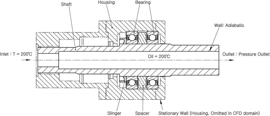
Figure 1. Computational domain and boundary conditions for the rotary joint model without an air gap (Case 1).
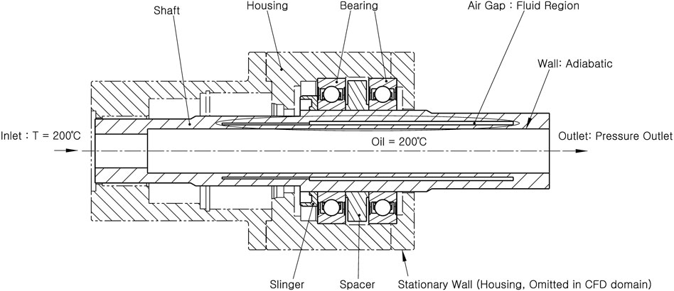
Figure 2. Computational domain and boundary conditions for the rotary joint model with an air gap (Case 2).
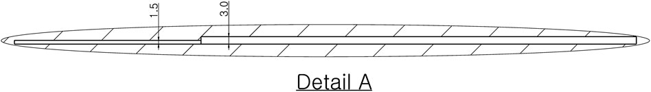
Figure 3. Detailed view of the air gap region with annotated geometric dimensions.
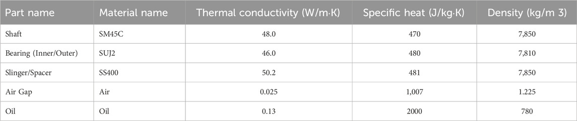
Table 1. Thermal properties of applied materials.
The boundary conditions were defined as follows: a constant temperature was imposed on the inner surface of the shaft to mimic heat exchange with the hot working fluid, and natural convection conditions were applied to the outer wall of the bearing, assuming exposure to ambient air. Thermal contact conductance was specified at the shaft–bearing interface to capture the effect of contact conduction. Symmetry conditions were applied about the central axis, allowing only half of the domain to be modeled to improve computational efficiency. The applied boundary conditions are summarized in Table 2.
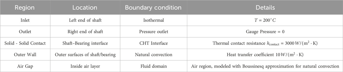
Table 2. Boundary conditions for thermal analysis.
3.2 Mesh configuration and independence test
The computational mesh employed in this study was an unstructured hybrid grid consisting of quadrilateral and triangular elements. Local refinement was applied near the shaft–bearing contact regions and within the air-gap, where steep thermal gradients were expected, in order to capture heat transfer with sufficient resolution. Figures 4, 5 illustrate the overall mesh configuration for Case 1 (No Air Gap) and Case 2 (With Air Gap), respectively, with insets highlighting the refined region around the air gap.
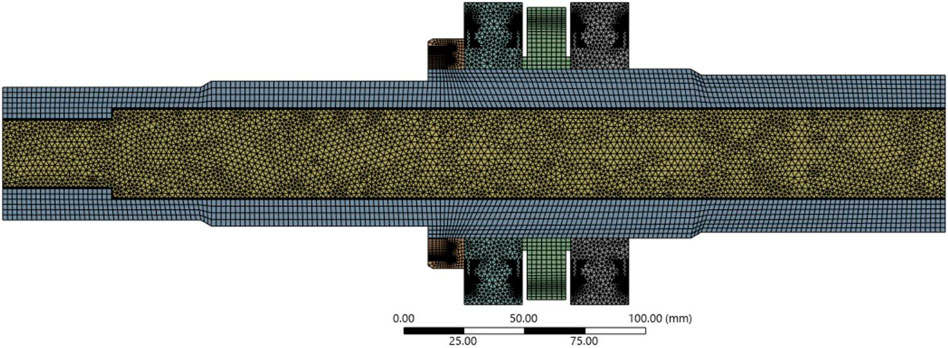
Figure 4. Mesh topology and boundary-layer refinement for the model without an air gap (Case 1).
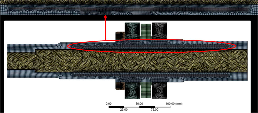
Figure 5. Mesh topology and boundary-layer refinement for the model with an air gap (Case 2).
A mesh-independence study was performed to ensure the numerical stability and reliability of the results. The number of elements was systematically varied from approximately 1.6 × 10⁶ to 4.5 × 10⁶, and the bearing-average and hotspot temperatures were compared. As shown in Figure 6, the results converged for meshes larger than about 2.0 × 10⁶ elements, with relative variations below 1% for Case 1 and approximately 1%–1.5% for Case 2 between the medium and fine meshes. Based on this analysis, a mesh with approximately 1.6 × 10⁶ elements was selected for the final simulations, as it offers an appropriate balance between computational efficiency and accuracy. The difference compared to the finer mesh remained within 2%, confirming that the conclusions are not affected by mesh density.
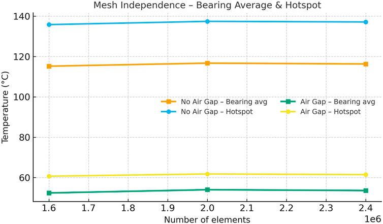
Figure 6. Mesh independence study results showing average and hotspot bearing temperatures versus element count, comparing Case 1 (No Air Gap) and Case 2 (With Air Gap).
This systematic verification confirms that the numerical solutions are essentially grid-independent and physically consistent. Although a formal Grid Convergence Index (GCI) was not computed, the results presented in Figure 6 clearly demonstrate sufficient mesh convergence for the purposes of this study.
3.3 Numerical methods and solver settings
The numerical simulations were carried out using ANSYS Fluent 2025 R1 (ANSYS Inc, 2023). The governing equations (continuity, momentum, and energy; Equations 1–4) were discretized using the finite volume method (FVM), and pressure–velocity coupling was achieved with the SIMPLE algorithm (Patankar, 1980; Versteeg and Malalasekera, 2007).
All simulations were performed under steady-state conditions, which is justified given the short thermal time constant of the system and the quasi-steady nature of the thermal field under high-speed rotation. The residual convergence criterion for the energy equation was set to 10–6 to ensure numerical accuracy. Second-order upwind schemes were employed to minimize numerical diffusion. The standard k-ε turbulence model was used to represent the flow within the air gap, as it has been widely validated for similar natural convection problems (Bejan, 2013).
Temperature-dependent density was linearized according to the Boussinesq approximation, and the thermophysical properties of all components were taken from standard references (Incropera and DeWitt, 2007; Çengel and Ghajar, 2011) and are summarized in Table 1. The key numerical parameters used in the simulations are listed in Table 3, with justification provided for the choice of turbulence model, Courant number, mesh resolution, and boundary conditions to ensure the robustness of the numerical setup.
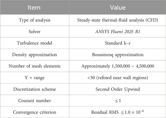
Table 3. CFD analysis settings and parameters.
These numerical methods and solver settings allowed for a quantitative assessment of the air gap’s influence on axial heat transfer in the rotary joint and ensured the reliability of the CFD-based results.
4 Results and discussion
This section presents the numerical results and discusses the influence of the air-gap design on the heat transfer characteristics of the rotary joint. First, the temperature distributions of Case 1 (No Air Gap) and Case 2 (With Air Gap) are compared to examine how the introduction of the air gap mitigates local bearing overheating.
Subsequently, the flow field and natural convection patterns within the air gap are analyzed to clarify the role of fluid motion in enhancing thermal resistance. The radial temperature profiles at the bearing cross-section are also examined to quantify both axial and radial thermal resistance effects.
Finally, the CFD results are compared with a one-dimensional thermal resistance model to verify the numerical validity and to analyze the differences between the two approaches. The findings are then compared with conventional coating-based thermal management techniques in terms of performance, cost, and reliability to highlight the engineering significance of this study.
4.1 Temperature distribution characteristics
Figures 7–10 present the temperature distributions of the baseline model (Case 1) and the improved model with an air gap (Case 2). In Case 1, heat generated by the hot fluid inside the shaft is directly conducted to the bearing region, leading to localized overheating near the inner race (bearing hotspot in Figure 7). This hotspot region represents a critical weakness, as it can accelerate lubricant degradation, material strength reduction, and localized thermal stress concentration. At higher rotational speeds, the increased contact pressure may further accelerate thermo-mechanical damage.
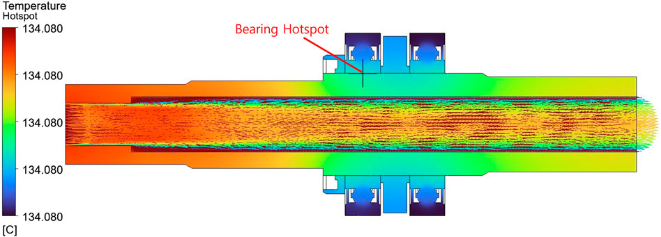
Figure 7. Velocity distribution on the mid-axial cross-section for the model without an air gap (Case 1), with scale fixed to 0 ∼ 4.0 m/s.
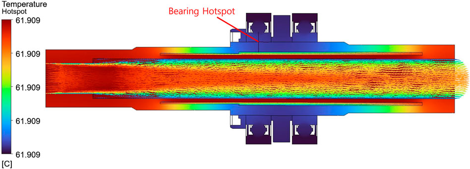
Figure 8. Velocity distribution on the mid-axial cross-section for the model with an air gap (Case 2), with scale fixed to 0 ∼ 4.0 m/s.
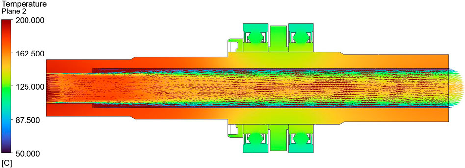
Figure 9. Local temperature field near the bearing contact region for the model without an air gap (Case 1) on the mid-axial cross-section, colormap 50 ∼ 200 °C.
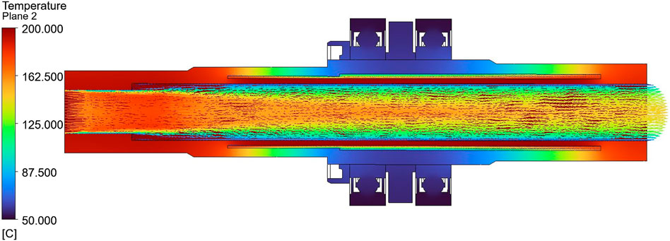
Figure 10. Local temperature field near the bearing contact region for the model with an air gap (Case 2) on the mid-axial cross-section, colormap 50 ∼ 200 °C.
In contrast, Case 2 shows that the air gap effectively interrupts the axial heat conduction path between the shaft and bearing. As shown in Figure 10, the formation of hotspots is suppressed, and the overall temperature level is significantly reduced compared with Case 1. This improvement is attributed to the combined effects of the air gap’s high thermal resistance and the natural convection induced by the temperature difference within the cavity, which helps redistribute heat. As a result, temperature rise in the bearing contact region is mitigated, reducing the risk of localized overheating.
Figures 8, 9, which present the temperature distributions along the entire shaft cross-section, also confirm these trends. In Case 1, high temperatures propagate continuously along the shaft, transferring heat to the outer race. In Case 2, the air gap acts as a thermal barrier, effectively blocking this conduction path and resulting in a significantly lower outer-race temperature and a more gradual axial temperature gradient.
For visual clarity, a consistent color scale (50 °C–200 °C) was applied to both cases. This enables a direct and intuitive comparison, making it evident that Case 2 exhibits both a lower overall temperature field and a smoother temperature gradient. These results confirm that the air-gap structure can serve as an effective passive insulation layer through a simple geometric modification. Quantitative comparisons are presented in Section 4.4, where the CFD results are validated against the one-dimensional thermal resistance model.
4.2 Flow and natural convection characteristics
In Case 2, natural convection is induced within the air layer between the shaft and bearing due to buoyancy effects. Figure 11 shows the streamline distribution inside the air gap, where ascending and descending air currents form a distinct circulation pattern. This circulation redistributes heat between the shaft surface and the outer race, explaining the difference in thermal behavior compared with Case 1, where conduction dominates.
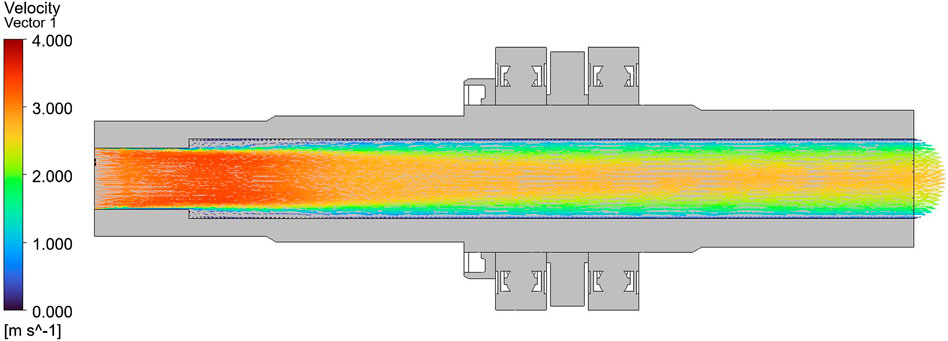
Figure 11. Overall temperature field of the rotary joint without an air gap (Case 1) on the mid-axial cross-section, colormap 50 ∼ 200 °C.
Figure 12 shows the velocity distribution, indicating relatively higher flow velocities near the center of the air gap, with a sharp decrease near the walls forming a typical boundary-layer profile. The maximum velocity remains below approximately 4 m/s, with most of the flow in the range of 1–2 m/s, indicating that laminar natural convection is the dominant mode of heat transfer. Together with the low thermal conductivity of air, this laminar convection enhances the air gap’s function as a thermal resistance layer.
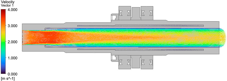
Figure 12. Overall temperature field of the rotary joint with an air gap (Case 2) on the mid-axial cross-section, colormap 50 ∼ 200 °C.
These findings demonstrate that the air gap not only blocks the conduction path but also promotes heat redistribution through buoyancy-driven laminar flow, thereby reducing thermal gradients. Consequently, the air gap serves as both a mechanical insulation layer and a thermal buffer, contributing to extended bearing life and improved system stability.
4.3 Radial temperature profile analysis
The radial temperature distribution of the bearing cross-section provides a key metric for quantifying the thermal blocking effect of the air gap. In this study, five measurement points were defined from the inner race (0%) to the outer race (100%), and the temperature profiles of Case 1 and Case 2 were compared.
Table 4 and Figure 13 present the temperatures and the percentage reduction of Case 2 relative to Case 1 at each location. At the inner race (0%), Case 1 shows approximately 134.1 °C, whereas Case 2 shows 61.91 °C, corresponding to a 53.8% reduction. Even at the outer race (100%), the temperature dropped from 106.5 °C (Case 1) to 52.24 °C (Case 2), representing a 50.9% decrease. Across the entire radial span, more than 50% temperature reduction was maintained, with a 52.4% decrease observed even at the 50% position (119.0 °C → 56.64 °C).
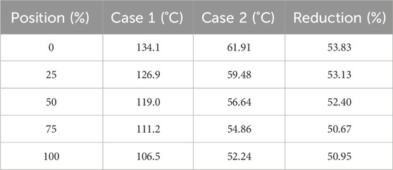
Table 4. Temperature distribution and reduction rate from inner to outer race.
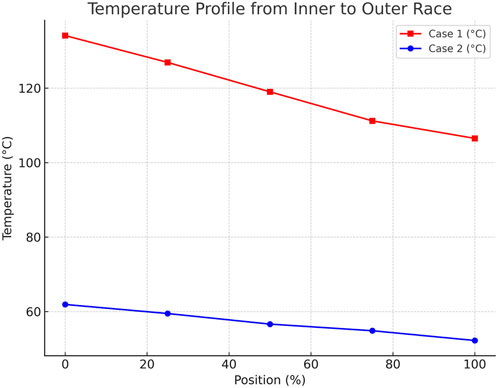
Figure 13. Radial temperature profile across the bearing from the inner race (0%) to the outer race (100%) comparing Case 1 (No Air Gap) and Case 2 (With Air Gap).
These results indicate that the air gap provides consistent thermal suppression not just locally but across the entire radial path. As shown in Figure 13, Case 1 exhibits a gradual temperature decay from the inner to the outer race, whereas Case 2 maintains uniformly lower temperatures with a relatively flat profile between 50% and 75% of the radius. This behavior suggests a shift in the dominant heat transfer mechanism from direct metal-to-metal conduction to indirect convection and radiation.
The effect is most pronounced near the inner race, where heat generation is concentrated, making the air gap particularly effective in relieving local thermal stress and preventing lubricant degradation. The maintained temperature reduction up to the outer race demonstrates the potential of this approach to improve overall thermal stability and extend bearing life.
4.4 Comparison between theoretical model and CFD
To verify the validity of the CFD results and to assess the usefulness of a simplified predictive approach during early design stages, a one-dimensional thermal resistance model was also employed. This model is based on conduction and a thermal resistance network, allowing rapid estimation of axial heat transfer. Owing to its simplicity and low computational cost, it serves as a practical tool for quick parametric studies of design variables such as material properties, thickness, and cross-sectional area. Although it cannot capture local phenomena in detail, it provides valuable insights into overall heat transfer trends from a design perspective.
As summarized in Table 5, the absolute bearing temperature predictions of the 1D model deviate considerably from the CFD results. This discrepancy arises because the 1D model accounts only for axial conduction and neglects other mechanisms such as natural convection, radiation, and thermal contact resistance. The difference is particularly pronounced in Case 2, where natural convection plays a significant role.
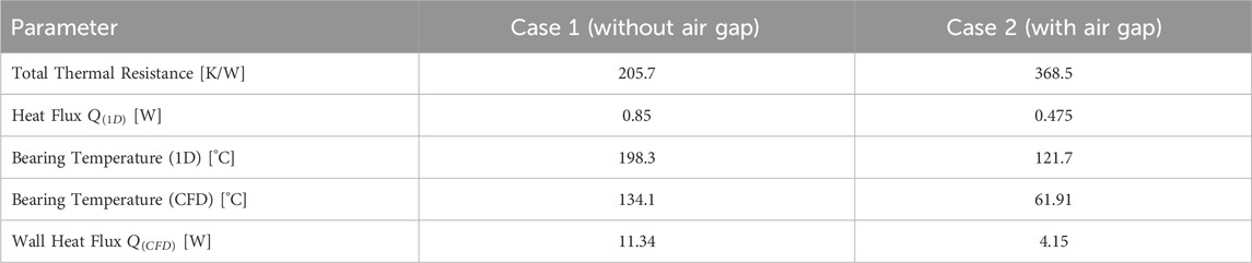
Table 5. Comparison of 1D theoretical model and CFD results for heat flux and bearing temperature.
Nevertheless, the simplified model correctly predicts the overall trends: the air gap increases thermal resistance, reduces heat flux, and lowers bearing temperature—consistent with the CFD results. This comparison provides two important insights: first, the 1D model, despite its limitations, is suitable for preliminary design screening and rapid parametric studies; second, CFD is essential in later stages of design to capture the detailed physics, including convection, radiation, and local thermal effects, for accurate design validation and optimization.
Thus, the difference between the two approaches should not be seen merely as numerical error but as an indicator of their respective roles and applicability. The 1D model offers a fast and simple guideline for early-stage design, whereas CFD provides a detailed and reliable prediction for final validation. Together, they form a complementary framework that strengthens the physical credibility of the proposed air-gap design.
4.5 Comparison with previous studies
The results of this study show a clear distinction from previously reported thermal management techniques. Thermal-spray coating technologies have been widely applied to reduce heat flux and protect substrates in high-temperature environments, with numerous applications reported in aerospace, power generation, and automotive industries (Fauchais et al., 2011; Meng et al., 2024). However, coatings are subject to delamination, cracking, fatigue-induced damage, and require periodic inspection and reapplication. In addition, the coating process is expensive and equipment-intensive, limiting its scalability (Hamrock et al., 2004).
In contrast, the air-gap design proposed in this study achieves significant thermal blocking effects through a simple geometric modification, without additional coatings or external devices. The CFD results confirm that inserting an air gap reduces bearing contact temperatures by more than 50%, alleviating local overheating, preventing lubricant degradation and strength loss, and ultimately extending bearing life and improving system reliability.
Because the air-gap design does not require external energy input or complex auxiliary systems, it is highly cost-effective. There is no need for periodic inspection or re-coating, and once implemented during the design stage, the solution provides long-term stability. Hence, in terms of performance, cost, and reliability, the air-gap approach offers a more balanced and robust solution compared with conventional coating-based methods (Kim, 2018; Park, 2015).
Moreover, this work contributes to the growing body of research on thermal management and lubrication strategies, including studies on air-gap insulation layers (Kim, 2020), oil–air lubrication heat transfer (Li et al., 2021), magnetorheological (MR) bearing thermal-fluid analyses (Vaziri et al., 2024), and grease-lubricated bearing film thickness prediction (Shetty et al., 2024). While these approaches provide meaningful insights, many still involve complex system configurations or limited applicability.
In conclusion, the proposed air-gap thermal insulation design represents not merely an alternative to existing technologies but a cost-effective and reliable paradigm shift in thermal management. Considering recent studies on transient temperature rise in high-speed rotors (Dong et al., 2024) and CFD-based thermal performance modeling of bearings (Zhang et al., 2025), the approach presented here provides a strong foundation for future practical implementation and extended research.
5 Conclusion
This study quantitatively investigated the effectiveness of an internal air-gap design in suppressing axial heat transfer in a high-temperature, high-speed rotary joint. A combination of CFD simulations and a one-dimensional thermal resistance model was employed, leading to the following key conclusions.
First, compared with the baseline configuration (Case 1), the air-gap configuration (Case 2) reduced the bearing contact temperature by more than 50%. This reduction was not merely the result of interrupting the conduction path, but was further enhanced by laminar natural convection within the air gap, which redistributed heat and mitigated thermal accumulation.
Second, analysis of the radial temperature profiles revealed consistent temperature reductions across the entire span from the inner to the outer race, along with the mitigation of local hotspots. This result suggests that the air-gap design can suppress lubricant degradation and local thermal stresses, thereby improving the thermal stability and extending the service life of the bearing.
Third, while the absolute temperature values predicted by the 1D theoretical model differed from the CFD results, both approaches showed the same overall trend of increased thermal resistance and reduced temperature with the introduction of the air gap. This confirms that the simplified model is suitable for rapid parameter screening during early design stages, whereas CFD is indispensable for final design validation and performance optimization.
Fourth, unlike conventional thermal-spray coatings, the air-gap design achieves significant thermal blocking performance without requiring expensive coating processes or periodic reapplication. This approach provides a well-balanced solution in terms of cost, reliability, and performance, while reducing maintenance requirements.
Overall, this study demonstrates that an air-gap structure is a simple yet highly effective passive thermal management strategy capable of mitigating local bearing overheating and enhancing system reliability. Nevertheless, this work was limited to steady-state conditions, and additional factors such as transient thermal behavior, thermo-structural coupling, and varying rotational speeds and loads must be considered for comprehensive evaluation. Future work will address these factors through extended simulations and, importantly, experimental validation using controlled heating and infrared thermography. These efforts will enable model calibration and design optimization, ultimately providing a robust foundation for the practical implementation and commercialization of the air-gap insulation concept.
Data availability statement
The raw data supporting the conclusions of this article will be made available by the authors, without undue reservation.
Author contributions
J-HK: Conceptualization, Methodology, Software, Writing – original draft, Writing – review and editing. B-HC: Funding acquisition, Investigation, Project administration, Resources, Writing – original draft.
Funding
The author(s) declare that financial support was received for the research and/or publication of this article. This study was supported by the Ministry of SMEs and Startups (MSS) of Korea under the Market Expansion-Type (Strategic) Technology Innovation Development Project for SMEs, titled “Development of a high-performance rotary joint for lithium-ion battery manufacturing equipment that uses an insulating and fluid-blocking ball bearing design to enable high-speed production at high temperatures” (Project No.: RS-2024-00487219, Ministry of SMEs and Startups, Korea). The authors gratefully acknowledge this financial support.
Conflict of interest
Authors B-HC was employed by KWANGJIN Corporation.
The remaining author declares that the research was conducted in the absence of any commercial or financial relationships that could be construed as a potential conflict of interest.
Correction note
This article has been corrected with minor changes. These changes do not impact the scientific content of the article.
Generative AI statement
The author(s) declare that no Generative AI was used in the creation of this manuscript.
Any alternative text (alt text) provided alongside figures in this article has been generated by Frontiers with the support of artificial intelligence and reasonable efforts have been made to ensure accuracy, including review by the authors wherever possible. If you identify any issues, please contact us.
Publisher’s note
All claims expressed in this article are solely those of the authors and do not necessarily represent those of their affiliated organizations, or those of the publisher, the editors and the reviewers. Any product that may be evaluated in this article, or claim that may be made by its manufacturer, is not guaranteed or endorsed by the publisher.
References
Bejan, A. (2013). Convection heat transfer. 4th Edn. Hoboken, NJ: John Wiley and Sons. doi:10.1002/9781118671627
Çengel, Y. A., and Ghajar, A. J. (2011). Heat and mass transfer: fundamentals and applications. 4th Edn. New York, NY: McGraw-Hill.
Dong, Y., Ma, Y., Qiu, M., Chen, F., and He, K. (2024). Analysis and experimental research of transient temperature rise characteristics of high-speed cylindrical roller bearing. Sci. Rep. 14, 711. doi:10.1038/s41598-024-51255-9
Fauchais, P., Heberlein, J. V. R., and Boulos, M. I. (2011). Thermal Spray Fundamentals: From Powder to Part. New York, United States: Springer Science & Business Media. doi:10.1007/978-0-387-68991-3
Hamrock, B. J., Schmid, S. R., and Jacobson, B. O. (2004). Fundamentals of fluid film lubrication. 2nd Edn. New York, NY: McGraw-Hill.
Incropera, F. P., and DeWitt, D. P. (2007). Fundamentals of heat and mass transfer. 6th Edn. Hoboken, NJ: John Wiley and Sons.
Kim, J. S. (2020). Thermal performance evaluation of heat blocking structure using air insulation layer. Trans. Korean Soc. Mech. Technol. 22 (1), 11–18.
Kim, D. H., and Kim, K. H. (2017). Thermal analysis and cooling performance evaluation of rotating bearings. J. Korean Soc. Tribol. Lubr. Eng. 33 (2), 85–92.
Li, M., Wang, Y., Zhang, H., and Liu, Q. (2021). Temperature rise characteristics for angular-contact ball bearings lubricated by oil-air: CFD simulation and experimental verification. Adv. Mech. Eng. 13 (1), 25–32. doi:10.1177/1687814021990927
Meng, Y., Saito, H., Bernard, C., Ichikawa, Y., and Ogawa, K. (2024). Optimal design of a cold spray nozzle for inner wall coating fabrication by combining CFD simulation and neural networks. J. Therm. Spray Technol. 33 (1), 3–16. doi:10.1007/s11666-024-01716-4
Park, S. J. (2015). Study on the application of Boussinesq approximation in natural convection heat transfer. J. Korean Soc. Therm. Environ. Eng. 14 (1), 23–30.
Patankar, S. V. (1980). Numerical heat transfer and fluid flow. Washington, DC: Hemisphere Publishing Corporation. doi:10.1201/9781482234213
Shetty, P., Meijer, R. J., Osara, J. A., Pasaribu, R., and Lugt, P. M. (2024). Effect of bearing size on film thickness in grease-lubricated axially loaded deep groove ball bearings. Tribol. Int. 197, 109748. doi:10.1016/j.triboint.2024.109748
Vaziri, S. A., Norouzi, M., Akbarzadeh, P., Kim, K. C., and Kim, M. (2024). Thermohydrodynamic analysis of magnetorheological conical bearings with conjugated heat transfer. Sci. Rep. 14, 20596. doi:10.1038/s41598-024-71759-8
Versteeg, H. K., and Malalasekera, W. (2007). An introduction to computational fluid dynamics: the finite volume method. 2nd edn. Harlow, United Kingdom: Pearson Education Ltd.
Keywords: air gap, axial heat transfer, bearing overheating, natural convection, CFD
Citation: Kim J-H and Choi B-H (2025) Numerical study of passive thermal management for a high-temperature, high-speed rotary joint using an internal air gap. Front. Mech. Eng. 11:1679597. doi: 10.3389/fmech.2025.1679597
Received: 04 August 2025; Accepted: 19 September 2025;
Published: 01 October 2025; Corrected: 06 October 2025.
Edited by:
Mahmoud Eltaweel, University of Hertfordshire, United KingdomReviewed by:
Junaid Ahmad Bhat, National Institute of Technology, IndiaGowhar Shafi Bhat, Indian Institute of Technology, India
Copyright © 2025 Kim and Choi. This is an open-access article distributed under the terms of the Creative Commons Attribution License (CC BY). The use, distribution or reproduction in other forums is permitted, provided the original author(s) and the copyright owner(s) are credited and that the original publication in this journal is cited, in accordance with accepted academic practice. No use, distribution or reproduction is permitted which does not comply with these terms.
*Correspondence: Jeong-Hwa Kim, cG93ZXJzaWRAa29wby5hYy5rcg==