 Bakhytzhan Donenbayev1
 Karibek Sherov2Bakhtiyor Mardonov3Lutfiddin Makhmudov3Sabit Magavin2
 Asset Rakishev1*Aibek Sherov2
- 1Department of Technological Equipment, Engineering and Standardization, Faculty of Mechanical Engineering, Abylkas Saginov Karaganda Technical University, Karagandy, Kazakhstan
- 2Department of Technological Machines and Equipment, Technical faculty, S. Seifullin Kazakh Agrotechnical Research University, Astana, Kazakhstan
- 3Department of Mechanical Engineering Technology, Faculty of Energy and Mechanical Engineering, Navoi State University of Mining and Technologies, Navoi, Uzbekistan
This study investigates the high-speed milling behaviour of heat-resistant martensitic–ferritic steel 15Kh12VMF, widely used in energy and power engineering components but difficult to machine due to its high hardness, strength and low thermal conductivity. An integrated approach combining experimental trials and finite element modelling was applied to assess the influence of cutting parameters on surface quality, tool wear and thermo-mechanical responses. Experiments were conducted on a vertical machining centre under dry cutting conditions using TiAlSiN-coated carbide tools. Milling parameters were varied within spindle speeds of 2000–12,000 revolutions per minute, feed rates of 500–4500 mm/min and cutting depths of 1–5 mm. Surface roughness was measured according to ISO 4287 standards. Finite element simulations were performed in ANSYS Workbench using the Johnson–Cook constitutive and damage models to reproduce chip formation, temperature distribution and cutting forces. Results indicated that increasing spindle speed from 3000 to 6000 revolutions per minute reduced surface roughness by up to 18%, whereas higher feed rates and depths of cut increased it by 25% and 32%, respectively. Optimal parameters were identified as 6000 revolutions per minute, 1500 mm/min and 2 mm. Tool wear accelerated beyond 6000–7000 revolutions per minute due to elevated cutting temperatures. Simulations predicted a peak temperature of 291.47 °C and cutting forces between –2500 N and +7500 N, consistent with experiments. This study provides validated reference data and modelling insights to support parameter optimisation and improve high-speed milling performance of martensitic–ferritic steels.
1 Introduction
The machining of difficult-to-cut materials presents a persistent challenge across various sectors of mechanical engineering. These materials are characterised by high hardness, strength, toughness, corrosion and heat resistance, along with low thermal conductivity – all of which contribute to rapid tool wear, increased production costs, and low productivity during cutting operations (Wojciechowski et al., 2020). One such material, heat-resistant high-alloy steel 15Kh12VMF, belongs to the martensitic-ferritic class and exhibits a Brinell hardness of HB 229–269. It is widely employed in critical components such as electrode boiler parts, steam turbine blades, gas distributor housings, cement rotary kiln bandages, and turbine fasteners, particularly in industrial environments like Gidro Stanko Servis limited liability company (LLC).
Under practical machining conditions, the processing of 15Kh12VMF presents severe limitations in terms of productivity and tool life due to low thermal conductivity, high hot strength and modest damping, which promote unstable plastic deformation during cutting (Romanenko et al., 2021; Wang et al., 2022; Kuczmaszewski et al., 2023). Beyond the base composition, alloying, heat treatment and surface engineering critically reshape the near-surface microstructure and, hence, machinability: duplex Cr–C–N ceramic coatings on tool steels alter hardness, adhesion and frictional behaviour at the tool–chip interface, with the deposited layer thickness strongly governed by processing parameters (Khalaj and Khalaj, 2014a; Khalaj and Khalaj, 2014b). Likewise, thermomechanical processing and subsequent heat treatment (e.g., multiaxial forging) in stainless steels produce ultrafine versus coarse grains with distinct sensitisation and corrosion responses (Kiahosseini et al., 2018), implying different heat generation/partitioning and contact mechanics in cutting. Collectively, these findings explain why microstructural state and engineered surface layers–while improving high-temperature strength and wear resistance–can increase cutting forces and intensify tool wear, underscoring the need to study high-speed milling of martensitic–ferritic steels such as 15Kh12VMF.
In addition to material-related factors, machining parameters exert a decisive influence on surface integrity and tool performance. Cutting speed, feed rate, and depth of cut control tool wear progression, chip formation, and surface roughness. Previous research has shown that variations in machining parameters and coolant strategies significantly affect tool wear, dimensional deviation, and surface finish when turning steels (Khalaj et al., 2024). Similar findings in high-speed machining of hardened alloys indicate that excessive feed rates and cutting depths accelerate thermal wear mechanisms and degrade surface quality, whereas parameter optimisation improves tool life and workpiece integrity (Khan and Ali, 2022; Tuli et al., 2024). Recent high-speed milling studies further affirm this: high spindle speeds can enhance surface finish but may amplify adhesive and diffusive wear if not carefully controlled (Wang et al., 2024; Zhang et al., 2024; Jamali et al., 2025; Sohail and Reddy, 2025). These collective insights underscore the necessity for systematic parameter optimisation in high-speed milling of martensitic–ferritic steels, an area that remains significantly understudied.
In recent years, high-speed milling (HSM) has emerged as a promising strategy for improving the machinability of heat-resistant alloys. Studies on titanium- and nickel-based alloys have shown that HSM can improve surface finish and reduce cutting forces, but also accelerates tool wear due to thermal softening and adhesion (Zha et al., 2020; Binali et al., 2023; Kuczmaszewski et al., 2023). However, investigations of martensitic-ferritic steels under HSM remain limited, despite their growing importance in power engineering and energy-intensive industries. This represents a clear research gap, as most existing knowledge is derived from alloys with very different thermal-mechanical properties.
This study addresses this research gap by applying an integrated approach that combines physical experiments with finite element simulation to analyse the HSM of 15Kh12VMF. Notably, the numerical and experimental components investigate different but complementary aspects of the process: experimental trials are used to assess surface integrity and identify optimal cutting parameters, while simulations are employed to study heat generation, tool–workpiece interactions, and chip formation at high temporal and spatial resolution. This distinction ensures that modelling is not simply a verification of the experiment but provides additional mechanistic insight into thermal and mechanical processes that are difficult to capture empirically.
In industrial contexts such as Kazakhstan, the implementation of high-speed Computer Numerical Control (CNC) technologies has only recently become feasible due to the introduction of modern machining centres by companies such as Victor Taichung (Taiwan), KAPP Nils (Germany), DOOSAN (Korea), and MODUL (Germany). Nevertheless, a key obstacle remains: the lack of validated reference data for selecting cutting parameters at high spindle speeds (5,000–12000 revolutions per minute (rpm)). Most legacy data are limited to conventional speeds (<2000 rpm) and cannot be reliably extrapolated to HSM regimes (Sherov et al., 2017; Jiang et al., 2023; Tuli et al., 2024; Tusupova and Makhmudov, 2023).
Finally, this work also holds practical value for regional industries that have only recently adopted high-speed CNC systems but lack access to robust parametric guidance for difficult-to-machine materials. By analysing both experimental and numerical results, this study offers a data-driven basis for selecting cutting regimes that balance surface quality, tool wear, and thermal effects in 15Kh12VMF steel.
2 Materials and methods
2.1 Experimental procedure
Experimental investigations of high-speed milling were conducted on a vertical machining centre V-Center P76 (Victor Taichung, Taiwan) equipped with a FANUC 0i-MD CNC controller at Gidro Stanko Servis LLC. The workpiece material was heat-resistant high-alloy steel 15Kh12VMF, supplied in the form of rectangular bars (100 × 80 × 70 mm). The chemical composition of the steel and its physical properties are provided in Table 1.
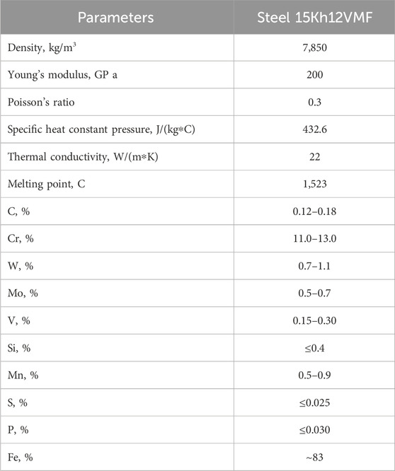
Table 1. Properties of workpieces.
A solid carbide end mill MC089 (Kennametal) was employed. The tool had a diameter of 16 mm, four flutes, a helix angle of 50°, and an overall length of 92 mm. The cutting edge was right-handed with a DIN 6535HA cylindrical shank. The tool was coated with TiAlSiN, which provided enhanced wear resistance under dry high-speed cutting conditions. The detailed geometry of the cutting tool is illustrated in Figure 1, and the experimental setup, including the tool–workpiece–fixture configuration, is shown in Figure 2. Tool specifications and the thermal–physical properties of the carbide substrate and coating are summarised in Table 2. The tool was mounted in an ER32 collet chuck to ensure rigid clamping and to minimise vibrations at high spindle speeds.
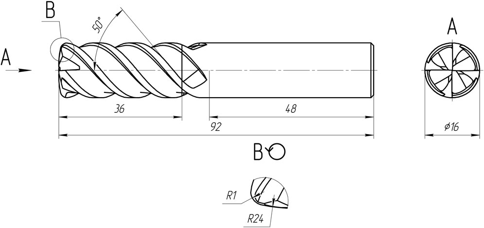
Figure 1. Solid carbide end mill MC089.
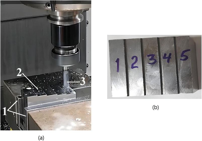
Figure 2. Experimental setup: (a) MC089 solid carbide end mill in the machining process. 1 – vice for clamping; 2 – processed sample; 3 – solid carbide end mill MC089 and (b) photograph of a processed sample made of 15Kh12VMF steel.
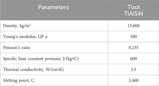
Table 2. Properties of the tool.
All milling trials were performed under dry cutting conditions, without any coolant or lubrication, in order to isolate the thermal–mechanical effects of the cutting parameters on surface integrity.
High-speed milling trials were performed under dry cutting conditions. The parameter windows were determined as a compromise between several factors: the capabilities of the machine–tool system, the manufacturer’s recommendations for carbide tools in heat-resistant steels, and the production constraints of Gidro Stanko Servis LLC related to surface-finish targets and cycle-time limits. In addition, short pilot cuts were conducted prior to testing to identify stable operating zones and to avoid chatter or premature tool failure. The study was organised as a parametric investigation following a one-factor-at-a-time (OFAAT) scheme, which enabled systematic variation of spindle speed, feed rate, and depth of cut within technologically relevant ranges, while other parameters were kept constant. This methodology provided clear identification of the main effects of cutting parameters on surface roughness under high-speed milling conditions. To ensure reliability and reproducibility, each experimental condition was repeated five times, and the resulting data were analysed to determine stable operating windows and minimise the influence of experimental variability. Thus, the following ranges were selected: spindle speed (nsp): 2000–12000 rpm; feed rate (S): 500–4,500 mm/min; depth of cut (t): 1–5 mm; cutting strategy: unidirectional linear milling at constant tool engagement. Workpieces were clamped in a high-precision mechanical vice with parallel alignment. Each cutting condition was applied along a 16 mm linear path.
Each test condition was repeated five times to ensure repeatability. Surface roughness (Ra) was measured using a TR100 portable surface tester according to ISO 4287, with a cut-off length of 0.8 mm. Three measurements were taken at different positions on each surface and averaged.
2.2 Input parameters for numerical modelling
The finite element simulations reproduced the experimental cutting conditions but with certain simplifications to optimise computational efficiency. The tool–workpiece system was modelled using a solid carbide end mill (MC089, Ø16 mm, 4-flute, helix angle 50°) and a rectangular workpiece scaled to 8 × 40 × 10 mm, preserving the local tool engagement geometry.
The workpiece material (15Kh12VMF) was described using the Johnson–Cook viscoplastic and damage models, incorporating strain hardening, strain-rate sensitivity, and thermal softening. The Johnson–Cook (J–C) constitutive relation is expressed as in Equation 1.
where σ is the flow stress, ε is the equivalent plastic strain, ε̇ is the plastic strain rate, and ε̇0 is the reference strain rate. The model parameters are defined as: A – initial yield stress (MPa), B – hardening modulus (MPa), n – strain hardening exponent, C – strain-rate sensitivity coefficient, m – thermal softening exponent, T – current temperature (K), Troom – room temperature (K), Tmelt – melting temperature (K).
The Johnson–Cook (J-C) parameters were taken from literature sources relevant to martensitic–ferritic steels (Bragov et al., 2020; Ghadiri et al., 2025; Le et al., 2025; Pandey and Samal, 2025). Temperature-dependent thermal conductivity and specific heat were included (Table 3).

Table 3. Johnson-Cook model parameters for workpieces.
Friction at the tool–chip interface was modelled using a constant Coulomb coefficient μ = 0.40, corresponding to dry machining of similar steels. Both the tool and workpiece were initially set to 22 °C (ambient laboratory conditions).
For baseline simulations, the spindle speed was set to nsp = 6,000 rpm, feed rate to S = 1,500 mm/min, and depth of cut to t = 2 mm, as determined experimentally to yield optimal surface finish.
For completeness, it should be noted that additional FEM implementation details – such as mesh refinement strategy, element convergence, contact modelling, and solver settings – are reported in section 3.
3 Numerical simulation of the high-speed milling process
Finite element simulations were performed in ANSYS Workbench (v2024 R2) to complement the experimental investigation and provide insight into thermo-mechanical phenomena occurring during high-speed milling of heat-resistant steel 15Kh12VMF. The tool–workpiece geometry, material properties, and cutting parameters used in the simulations corresponded to those described in Section 2.2.
3.1 Geometry and model development
The geometric model of the tool–workpiece system was developed using the Kompas-3D CAD software. A solid carbide end mill (MC089, Ø16 mm) was modelled based on the manufacturer’s technical drawing, incorporating its shank, helix angle (50°), cutting edge radius, and flute geometry. The tool had a flat-end profile with four helical flutes and a DIN6535HA cylindrical shank. Minor geometric features such as chip breakers and internal coolant channels were omitted to simplify the meshing process and reduce simulation time. The resulting 3D geometry was exported in STEP format and imported into ANSYS Workbench for finite element analysis.
The workpiece was represented as a rectangular prism with dimensions 8 × 40 × 10 mm, scaled down from the experimental sample to improve computational efficiency while preserving tool–workpiece contact conditions. The coordinate system was aligned such that the Y-axis corresponded to the feed direction (tool movement), the Z-axis to the spindle axis (rotation), and the X-axis to the depth of cut. Figure 3 shows the complete assembly of the tool and workpiece within the simulation environment.
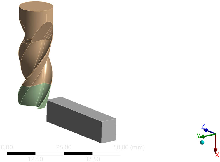
Figure 3. Three-dimensional model of the tool-workpiece system.
3.2 Material properties and failure model
The thermomechanical behaviour of 15Kh12VMF during high-speed milling was represented using the Johnson–Cook viscoplastic and damage models, which account for strain hardening, strain-rate sensitivity, and thermal softening. Model parameters were calibrated using literature data (Bragov et al., 2020; Ghadiri et al., 2025; Le et al., 2025; Pandey and Samal, 2025).
Adiabatic heating due to plastic work was considered, assuming negligible heat loss during chip formation. Chip separation was modelled using the Johnson–Cook fracture criterion, with element erosion activated when the accumulated damage parameter reached unity (D = 1).
3.3 Contact modelling and boundary conditions
Contact interactions between the cutting tool and the workpiece were defined using the surface-to-surface contact formulation in ANSYS Explicit Dynamics. The solid carbide end mill was treated as a rigid body due to its higher stiffness, while the workpiece was fully deformable. The rake, clearance, and flank faces of the tool were designated as the contact surface, with the corresponding region on the workpiece assigned as the target surface (Figure 4). Friction at the interface was modelled using a constant Coulomb coefficient (μ = 0.40).
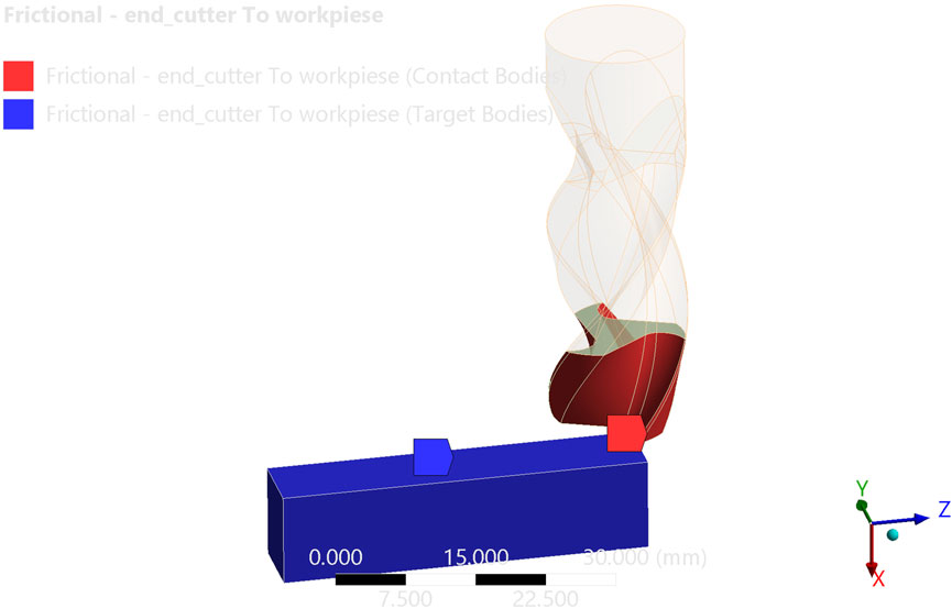
Figure 4. Interaction of the tool with the workpiece.
The tool was assigned a prescribed angular velocity about the X-axis, while its translational motion was fully constrained. Feed motion was applied by translating the workpiece along the Z-axis. The bottom face of the workpiece was fixed in all degrees of freedom to replicate clamping. Both the tool and the workpiece were initially set to a uniform temperature of 22 °C.
3.4 Finite element mesh and solver settings
A three-dimensional unstructured mesh was generated in ANSYS Workbench using quadratic tetrahedral elements for the carbide tool and deformable workpiece. Element sizing was refined adaptively: the minimum edge length in the cutting-edge vicinity was 0.10 mm, providing at least six elements across the undeformed chip thickness, whereas regions remote from the cutting zone were coarsened to 0.80 mm. The final mesh contained approximately 1.86 million elements for the workpiece and 3.7 million elements for the tool, as illustrated in Figure 5.

Figure 5. Finite element mesh of the model.
A mesh-convergence study was performed with characteristic element sizes of 0.20, 0.15 and 0.10 mm in the cutting zone. Reducing the element size from 0.20 mm to 0.10 mm changed the predicted cutting forces by < 5% and the maximum temperature by < 5%, confirming that the adopted mesh offers an adequate balance between accuracy and computational cost.
Transient cutting was simulated using a central difference time integration scheme. Automatic mass scaling was activated to maintain a stable time increment of ≈1 × 10⁻¹⁰ s, well below the Courant stability limit, without altering inertial effects relevant to high-speed cutting.
3.5 Scientific contribution of the simulation approach
The numerical simulation in this study was not intended to merely replicate experimental results but to complement them by providing access to internal thermo-mechanical phenomena during high-speed milling of heat-resistant steel. While experiments focused on surface quality and tool performance, simulation enabled analysis of stress distribution, chip formation, and heat accumulation - quantities difficult to measure directly.
The finite element model was calibrated specifically for 15Kh12VMF using the Johnson-Cook viscoplastic and damage models, accounting for strain-rate effects and thermal softening. Temperature-dependent properties, frictional heating, and thermal contact conductance at the chip-tool interface were included to improve realism under industrially relevant cutting conditions.
This integrated approach contributes new data and process understanding for 15Kh12VMF, a material underrepresented in high-speed machining literature. The findings support parameter optimisation in the absence of reference data and can inform future studies involving tool wear, coated inserts, and advanced cooling methods.
By combining validated experiments with physics-based modelling, the study offers a generalisable framework for investigating machinability of difficult-to-cut steels under high-speed regimes, relevant to modern production environments.
4 Results and discussion
Experimental high-speed milling of heat-resistant steel 15Kh12VMF was carried out using a solid carbide end mill MC089. The influence of cutting parameters on surface roughness (Ra) was investigated. The results indicate that this influence is non-linear and interdependent across different parameters.
Figure 6 presents the variation of surface roughness with spindle speed, feed rate, and depth of cut. The scatter between specimens was within 5%, which indicates good repeatability of the experiments. As shown in Figure 6A, increasing the spindle speed generally leads to improved surface finish (i.e., lower Ra values), especially at moderate feed rates. In contrast, Figure 6B demonstrates that increasing feed rate results in a noticeable deterioration of surface quality. Similarly, an increase in cutting depth contributes to a rougher machined surface.
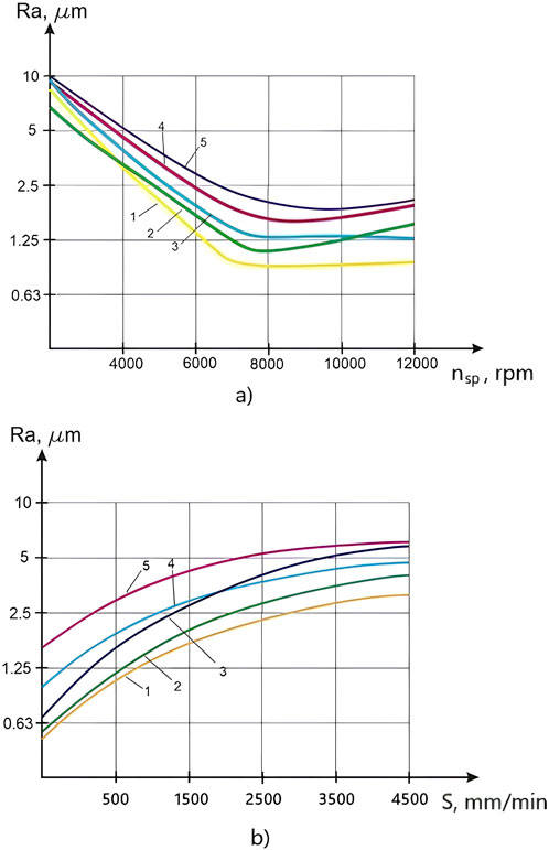
Figure 6. Surface roughness (Ra) as a function of cutting parameters during high-speed milling with the MC089 carbide end mill: (a) dependence on spindle speed (nsp), at fixed depth of cut t = 2 mm and varying feed rates - S1 = 500 mm/min; S2 = 1,500 mm/min; S3 = 2,500 mm/min; S4 = 3,500 mm/min; S5 = 4,500 mm/min; (b) dependence on feed rate (S), at fixed spindle speed nsp = 6,000 rpm and varying depths of cut - t1 = 1 mm; t2 = 2 mm; t3 = 3 mm; t4 = 4 mm; t5 = 5 mm.
Taking into account both productivity requirements and the surface finish specifications set by Gidro Stanko Servis LLC, the following combination of parameters was identified as optimal for high-speed milling of 15Kh12VMF: spindle speed nsp = 6,000 rpm, depth of cut t = 2 mm, and feed rate S = 1,500 mm/min.
Analysis of Figure 6A indicates that surface roughness remains nearly constant in the spindle speed range of 6,000–12000 rpm. However, this apparent stability is misleading, as tests at spindle speeds above 6,000 rpm were not performed due to accelerated tool wear. Visible signs of wear were already observed at nsp = 6,000 rpm, suggesting the onset of thermal degradation mechanisms.
Premature tool wear is primarily attributed to excessive heat generation in the cutting zone. As reported in prior studies (Khan and Ali, 2022; Wang et al., 2022; Binali et al., 2023), elevated temperatures promote a shift in tool failure mode – from gradual abrasive wear to more severe chipping and flaking – significantly reducing tool life. In addition, during intermittent milling of heat-resistant alloys, the tendency of workpiece material to adhere to the cutting edge upon exit intensifies wear and promotes edge breakage.
Several factors contribute to this thermal challenge: high friction coefficients at the tool–workpiece interface, low thermal conductivity of the materials, elevated specific cutting forces, difficulties in supplying cooling agents to the cutting zone, and a low chip compression ratio. These combined effects highlight the need for deeper investigation into the thermal-mechanical behaviour of such systems under high-speed milling conditions.
To address these challenges and gain insight into tool–workpiece interactions, a finite element simulation of the milling process was conducted in ANSYS Workbench (WB). Figure 7 shows the chip formation zone, where material removal is modelled via element erosion over a tool engagement distance of 125.78 mm.
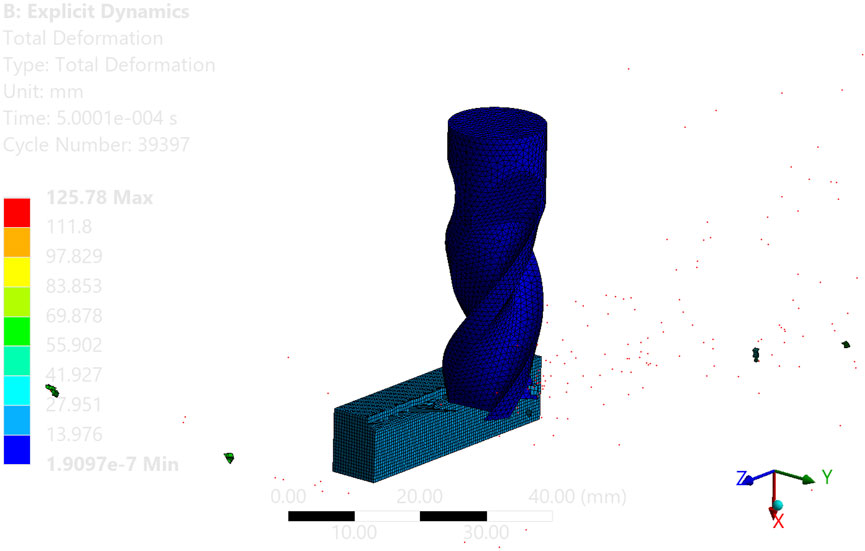
Figure 7. Simulated chip formation during high-speed milling.
Given the nonlinearity of the cutting process, equivalent plastic deformation in the surface layer was evaluated (Figure 8), providing insight into potential surface integrity issues.

Figure 8. Equivalent plastic strain distribution in the workpiece.
Contact forces along all three axes were extracted from the simulation and are illustrated in Figure 9. The force profiles exhibit dynamic fluctuations: X-axis forces oscillate between −2500 N and +2500 N, Y-axis forces vary from −2000 N to +2000 N, Z-axis forces remain consistently positive, peaking around +7500 N.
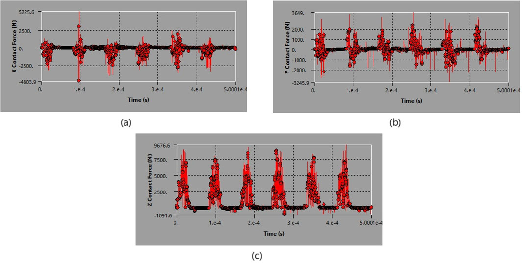
Figure 9. Contact forces in the tool–workpiece interaction: (a) X-axis, (b) Y-axis, (c) Z-axis.
Thermal analysis results are shown in Figure 10. As the tool engages the workpiece, the temperature in the contact zone rises sharply, reaching a steady-state value of approximately 291.47 °C. This confirms the thermal severity of high-speed milling for heat-resistant materials.
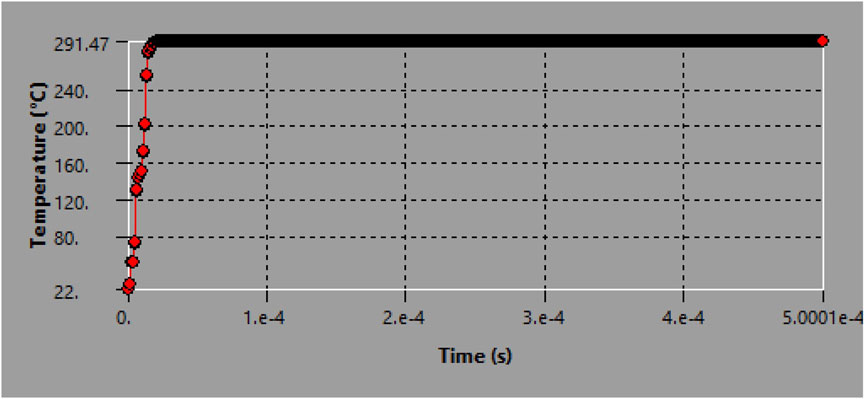
Figure 10. Temperature distribution in the contact region during milling.
5 Conclusion
1. Experimental investigations demonstrated that at a constant depth of cut (t = 2 mm), increasing the spindle speed (nsp) from 4,000 to 6,000 rpm reduced the surface roughness (Ra) from approximately 3.2–5.0 μm to 1.25–2.5 μm, while at 7,000 rpm Ra reached 0.95–2.2 μm depending on the feed rate. Further increases in spindle speed beyond 6,000 rpm did not result in significant improvement due to accelerated tool wear.
2. At a spindle speed of 6,000 rpm, increasing the feed rate (S) from 500 to 4,500 mm/min led to a rise in Ra from approximately 1.0–1.8 μm to 3.3–6.5 μm, with the effect being more pronounced at greater depths of cut.
3. The optimal high-speed milling parameters for 15Kh12VMF steel were identified as nsp = 6,000 rpm, t = 2 mm, and S = 1,500 mm/min, providing a balanced compromise between surface quality and productivity.
4. Finite element simulations confirmed the thermal severity of the process, with cutting zone temperatures reaching approximately 291.5 °C. This finding is consistent with experimental observations and explains the onset of accelerated tool wear at higher cutting speeds.
Data availability statement
The original contributions presented in the study are included in the article/supplementary material, further inquiries can be directed to the corresponding authors.
Author contributions
BD: Formal Analysis, Data curation, Funding acquisition, Software, Validation, Writing – original draft. KS: Writing – original draft, Conceptualization, Supervision. BM: Writing – original draft, Investigation, Methodology, Resources. LM: Investigation, Resources, Writing – original draft. SM: Data curation, Investigation, Validation, Writing – review and editing. AR: Formal Analysis, Writing – review and editing. AS: Formal Analysis, Writing – review and editing.
Funding
The author(s) declare that financial support was received for the research and/or publication of this article. This research was funded by the Science Committee of the Ministry of Science and Higher Education of the Republic of Kazakhstan (Grant No. AP19175058).
Conflict of interest
The authors declare that the research was conducted in the absence of any commercial or financial relationships that could be construed as a potential conflict of interest.
Generative AI statement
The author(s) declare that no Generative AI was used in the creation of this manuscript.
Any alternative text (alt text) provided alongside figures in this article has been generated by Frontiers with the support of artificial intelligence and reasonable efforts have been made to ensure accuracy, including review by the authors wherever possible. If you identify any issues, please contact us.
Publisher’s note
All claims expressed in this article are solely those of the authors and do not necessarily represent those of their affiliated organizations, or those of the publisher, the editors and the reviewers. Any product that may be evaluated in this article, or claim that may be made by its manufacturer, is not guaranteed or endorsed by the publisher.
References
Binali, R., Demirpolat, H., Kuntoğlu, M., and Sağlam, H. (2023). Machinability investigations based on tool wear, surface roughness, cutting temperature, chip morphology and material removal rate during dry and MQL-assisted milling of nimax mold steel. Lubricants 11 (3), 101. doi:10.3390/lubricants11030101
Bragov, A. M., Igumnov, L. A., Konstantinov, A.Yu., and Lomunov, A. K. (2020). Vysokoskorostnaya deformatsiya materialov razlichnoy fizicheskoy prirody: monografiya. Nizhny Novgorod, 299.
Ghadiri, M. M., Agyapong, J., Boakye-Yiadom, S., and Jian, C. (2025). Rate dependence of high strength steels mechanical behavior: characterization, modelling and impact applications. Int. J. Impact Eng. 206, 105454. doi:10.1016/j.ijimpeng.2025.105454
Jamali, A., Kashyap, A., Schneider, J., Stueber, M., and Schulze, V. (2025). Grey-box modelling for tool wear prediction in milling: fusion of finite element insights, time-resolved cutting signals and metaheuristic feature selection. Wear 580–581, 206292. doi:10.1016/j.wear.2025.206292
Jiang, Y., Yue, H., Li, Q., Ding, G., and Wang, X. (2023). Study on the machinability of Ni-based superalloy by milling parameters and cooling methods under minimal quantity lubrication. Appl. Sci. 13 (5), 2773. doi:10.3390/app13052773
Khalaj, G., and Khalaj, M.-J. (2014a). Application of ANFIS for modeling of layer thickness of chromium carbonitride coating. Neural comput. Appl. 25, 685–694. doi:10.1007/s00521-012-1290-x
Khalaj, G., and Khalaj, M.-J. (2014b). Modeling layer thickness of duplex ceramic (chromium carbonitride) coating on cold work tool steel using fuzzy logic. Integr. Ferroelectr. 152 (1), 2229–2237. doi:10.3233/IFS-130896
Khalaj, G., Haghparast, M.-J., Salari, M.-S., and Motahari, A. (2024). Effect of R410a coolant on tool wear, dimensional deviation and surface roughness in turning of AISI 1045 steel. Eng. Res. Express 6 (3), 035521. doi:10.1088/2631-8695/ad63f8
Khan, Z., and Ali, S. (2022). High-speed machining of heat-resistant alloys: tool wear transition due to high cutting temperature. J. Manuf. Process. 78, 432–442. doi:10.1016/j.jmapro.2022.05.001
Kiahosseini, S. R., Mohammadi Baygi, S. J., Khalaj, G., Khoshakhlagh, A., and Samadipour, R. (2018). A study on structural, corrosion, and sensitization behavior of ultrafine and coarse grain 316 stainless steel processed by multiaxial forging and heat treatment. J. Mater. Eng. Perform. 27, 271–281. doi:10.1007/s11665-017-3095-7
Kuczmaszewski, J., Zaleski, K., Matuszak, J., Pieśko, P., and Barszcz, M. (2023). Investigation of the impact of high-speed machining in the milling process of titanium alloy on tool wear, surface layer properties, and fatigue life of the machined object. Materials 16, 5361. doi:10.3390/ma16155361
Le, T.-T., Pham, H. T., Khac Doan, H., and Asteris, P. G. (2025). Experimental and computational investigation of the effect of machining parameters on the turning process of C45 steel. Adv. Mech. Eng. 17 (2), 16878132251318170. doi:10.1177/16878132251318170
Pandey, S. K., and Samal, M. K. (2025). Experimental evaluation of temperature and strain-rate-dependent mechanical properties of austenitic stainless steel SS316LN and a new methodology to evaluate parameters of johnson-cook and ramberg-osgood material models. Solids 6, 7. doi:10.3390/solids6010007
Romanenko, A. M., Shatko, D. B., Nepogozhev, A. A., and Karavaev, Ya.S. (2021). Abrasive machining of high-alloy corrosion resistant steels by example of 12Kh18N10T. Bull. Air Def. Concern Almaz-Antey (3), 98–106. doi:10.38013/2542-0542-2021-3-98-106
Sherov, K., Sikhimbayev, M., Mazdubay, A., Sherov, A., Rakishev, A., Mussaev, M., et al. (2017). The research of the temperature impact in tool-workpiece contact on the quality of the cut at thermofrictional cutting. Mech. Mech. Eng. 21 (3), 755–762.
Sohail, S., and Reddy, B. C. M. (2025). Optimizing surface roughness in end milling of additively and conventionally manufactured components of 18Ni300 maraging steel with minimum quantity lubrication. Eng. Res. Express 7 (1), 015503. doi:10.1088/2631-8695/ada22e
Tuli, N. T., Amin, A. K. M. N., Kaisar, R., Dhrubo, F. I., and Rashid, A. B. (2024). Optimisation of machining parameters in high-speed end milling of hardened AISI H13 die steel by integrating RSM and GA. Adv. Mater. Process. Technol. 11, 1564–1582. doi:10.1080/2374068X.2024.2397153
Tusupova, S. O., and Makhmudov, L. N. (2023). Sostoyanie problemy obrabotki trudnoobrabatyvaemyh materialov. Sci. Technol. Kazakhstan (3), 71–82. doi:10.48081/QLOD6747
Wang, R., Yang, D., Wang, W., Wei, F., Lu, Y., and Li, Y. (2022). Tool wear in nickel-based superalloy machining: an overview. Processes 10 (11), 2380. doi:10.3390/pr10112380
Wang, Q., Zhao, Y., Zhu, X., Zhang, J., Wei, Z., Jin, Z., et al. (2024). Effect of milling parameters on machinability of SA508-3 steel in high-speed milling with uncoated and coated carbide tools. Proc. Institution Mech. Eng. Part B J. Eng. Manuf. 238 (8), 1157–1171. doi:10.1177/09544054231189604
Wojciechowski, S., Królczyk, G. M., and Maruda, R. W. (2020). Special issue: advances in hard-to-cut materials: manufacturing, properties, process mechanics and evaluation of surface integrity. Materials 13, 2240. doi:10.3390/ma13030612
Zha, J., Yuan, Z., Zhang, H., Li, Y., and Chen, Y. (2020). Nickel-based alloy dry milling process induced material softening effect. Materials 13, 3758. doi:10.3390/ma13173758
Keywords: high-speed milling, heat-resistant high-alloy steel, machinability, experimental study, numerical simulation
Citation: Donenbayev B, Sherov K, Mardonov B, Makhmudov L, Magavin S, Rakishev A and Sherov A (2025) Research and modelling of the high-speed milling process of heat-resistant high-alloy steel. Front. Mech. Eng. 11:1680007. doi: 10.3389/fmech.2025.1680007
Received: 05 August 2025; Accepted: 29 August 2025;
Published: 15 September 2025.
Edited by:
Abdelmageed A. Elmustafa, Old Dominion University, United StatesReviewed by:
Gholamreza Khalaj, Islamic Azad University Saveh, IranBrahim Chermime, University of Khenchela, Algeria
Copyright © 2025 Donenbayev, Sherov, Mardonov, Makhmudov, Magavin, Rakishev and Sherov. This is an open-access article distributed under the terms of the Creative Commons Attribution License (CC BY). The use, distribution or reproduction in other forums is permitted, provided the original author(s) and the copyright owner(s) are credited and that the original publication in this journal is cited, in accordance with accepted academic practice. No use, distribution or reproduction is permitted which does not comply with these terms.
*Correspondence: Asset Rakishev, YS5yYWtpc2hldkBrdHUuZWR1Lmt6