 Phong-Dien Nguyen1
 Trong-Du Nguyen
- 1ITD-HUST Lab, School of Mechanical Engineering, Hanoi University of Science and Technology (HUST), Hanoi, Vietnam
- 2Department of Mechanical Engineering, Ming Chi University of Technology, New Taipei City, Taiwan
Early fault diagnosis of transmission systems is critical for Smart Manufacturing, but it is challenging due to the scarcity of real-world fault data. This paper addresses the issue by proposing a strain energy-based method to accurately model the time-varying mesh stiffness of a spur gear with a tooth root crack. This model accounts for bending, axial, shear, and tooth root foundation deflections, along with crack factors such as depth and propagation. Based on this stiffness formulation, a six-degree-of-freedom lumped-parameter dynamic model was developed to simulate the system’s vibration response. Simulation results show that statistical features like RMS and Kurtosis, along with the appearance of sidebands in the frequency spectrum, clearly reflect the severity of the crack. These fault features are ideal inputs for AI/ML/DL models, helping to overcome the lack of data for training and optimizing fault diagnosis algorithms in Smart Manufacturing.
1 Introduction
In the era of Smart Manufacturing and Industry 4.0, the primary objective is to comprehensively optimize production processes, aiming for exceptional automation, efficiency, and reliability. To achieve this goal, Artificial Intelligence (AI) and the Internet of Things (IoT) have emerged as pioneering technologies, offering the capability to collect and analyze real-time data, thereby enabling intelligent decision-making (Gauder et al., 2023). The integration of IoT sensor systems, such as MEMS sensors, allows for continuous monitoring of machine conditions. Simultaneously, advanced AI algorithms like Machine Learning (ML) and Deep Learning (DL) transform vast amounts of data into valuable information for fault diagnosis and predictive analysis (Wang et al., 2022). Notably, the concept of a Digital Twin (Srivastava and Tiwari, 2025), a virtual model of a physical system continuously updated with real-time data, serves as a robust framework for precise monitoring and predictive maintenance within a smart manufacturing environment. These systems enable flexible quality control and enhance the overall performance of the production line, operating based on principles similar to the smart manufacturing system illustrated in Figure 1.
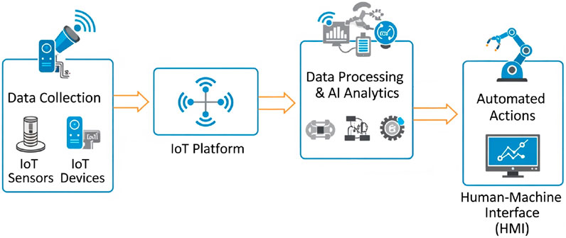
Figure 1. Smart manufacturing system diagram integrating AI and IoT.
However, gear systems, which are core transmission components in most mechanical systems ranging from industrial to military applications, are highly susceptible to various faults such as wear, pitting, and tooth cracks or fractures due to harsh operating conditions (Ma et al., 2012). These failures not only cause abnormal noise and vibrations but also pose a risk of sudden breakdown, leading to significant economic loss and severe safety hazards. Among these, The fillet area is a region of stress concentration particularly bending stress and is frequently subjected to dynamic and impact loads, making it highly susceptible to fatigue cracking. Such cracks not only reduce the meshing stiffness (Liu et al., 2024) but also lead to increased vibration and noise levels, and may eventually result in tooth breakage, causing transmission failure and severe damage to surrounding mechanical components.
To address these challenges, accurate and timely fault diagnosis of gears is of paramount importance. Although traditional diagnostic methods based on manual vibration signal analysis have been widely used, they often face limitations in extracting complex fault features, especially when the fault signal is weak or contaminated by high noise (Gauder et al., 2023). Furthermore, a major obstacle in developing robust AI/ML/DL models for fault diagnosis is the difficulty and high cost associated with collecting sufficient fault data from real-world mechanical systems. This is particularly true for rare fault types or when data is required from multiple operating conditions. Research has shown that collecting real fault data can be “nearly impossible” or “extremely difficult” (Liu et al., 2020; Koutsoupakis et al., 2023).
In light of these obstacles, the use of numerical simulation and dynamic modeling has emerged as a promising alternative for generating high-quality synthetic fault data. These simulation methods are diverse, each with distinct advantages and disadvantages tailored to specific research objectives. The Finite Element Method (FEM) is a powerful tool for detailed, localized stress and strain analysis, particularly useful for accurately determining the effect of faults like cracks or pitting on tooth stiffness (Liu et al., 2020). While FEM offers high fidelity, its substantial computational cost and long processing times make it impractical for generating large-scale datasets for machine learning model training. Conversely, Multibody Dynamics (MBD) models focus on simulating the motion and interaction of mechanical components within a complex system, providing a holistic view of the system’s dynamic response (Koutsoupakis et al., 2023). However, modeling small, localized faults can be challenging with this approach. To address these limitations, lumped parameter models have become an excellent choice for generating data for AI algorithms (Gecgel et al., 2018; Sharma et al., 2024; Liu et al., 2025). In this method, the gear system is simplified into an assembly of masses, springs, and dampers, enabling computationally efficient simulation of the system’s global vibrational responses. Despite a lower level of detail compared to FEM, lumped parameter models excel at generating a large volume of diverse vibration data under various fault scenarios and operating conditions. This rich source of synthetic data is crucial not only for overcoming the scarcity of real-world data but also for mitigating the issue of data imbalance—a common challenge in machine learning where healthy data significantly outweighs fault data. Furthermore, using this high-quality simulated data as a training foundation allows AI/ML/DL models to automatically learn and extract complex fault features, even in noisy environments, thereby enhancing their generalization capability and accuracy in practical diagnostic applications.
In this paper, we present a detailed investigation into the dynamic response and mesh stiffness modeling of gears with a tooth root crack, which provides a crucial foundation for AI-based fault diagnosis in Smart Manufacturing. To achieve this, we propose a novel strain energy-based method to accurately model the time-varying mesh stiffness of the cracked gear. This model is developed by considering detailed factors such as the crack’s depth, orientation, and propagation along the entire tooth width, as well as bending, axial, shear, and tooth root foundation deflections. Based on this detailed stiffness formulation, a six-degree-of-freedom lumped parameter dynamic model is constructed to simulate the vibrational response of the cracked gear system.
The results of this study are expected to provide a solid scientific foundation for condition monitoring and fault diagnosis methods of gears in industrial applications, thereby enhancing the reliability and operational efficiency of mechanical systems.
2 Proposed model construction
2.1 Related works
The dynamics of gear mechanisms have attracted growing interest, with numerous studies addressing various aspects of gear vibration and fault modeling. Van Khang et al. (2004) developed a model for geared transmission to diagnose gear failures, representing the gear mesh as rigid disks connected by a spring-damper system along the contact line, the model incorporated static transmission error as a displacement excitation in the mesh, with time-varying mesh stiffness and zero backlash under high torque to predict sideband amplitude in the presence of distributed gear faults. Tordion and Gauvin (1977) studied the stability of two-stage gear systems using a simplified model with time-varying mesh stiffness, showing that phase differences between stages significantly influence instability ranges. Sakai et al. (1981) introduced a nonlinear torsional model for multi-speed transmissions, demonstrating that clutch stiffness plays a key role in vibration reduction. Kumar et al. (1985) adopted a state-space approach to evaluate how dynamic loads and system stability are affected by stiffness and damping parameters, while still improving computational efficiency. Several studies have focused on incorporating physical defects and frictional effects. Iida et al. (1985) used a simplified model to examine the influence of tooth surface roughness and lubrication on sliding-direction vibration. Bartelmus (2001) extended dynamic models to include translational and rotational motions, showing that increased gear wear leads to higher friction forces. Howard et al. (2001) investigated the effects of cracks and nonlinear friction using finite element and energy-based models, respectively. Their findings emphasized the significant reduction in torsional stiffness due to cracks and the dominant role of bending energy over other forms. Kahraman and Singh (1991) explored frequency response characteristics in gear–rotor–bearing systems, revealing a strong dependency between meshing behavior and backlash when mesh stiffness varies over time.
Most previous studies have primarily focused on dynamic analysis for design, manufacturing, or operational purposes under ideal working conditions. Although some recent works have developed dynamic models that incorporate gear faults for diagnostic purposes, many of these models still assume the mesh stiffness as a simple sinusoidal or Fourier function, and often fail to fully account for the specific mechanical effects of gear damage—such as tooth cracks—on system response, as well as the role of fillet correction. In particular, the modeling of mesh stiffness remains incomplete when it comes to detailed factors such as root foundation deformation in the presence of cracks, or the spatial distribution of cracks along the tooth width. To address this research gap, the present study develops a comprehensive model for evaluating the mesh stiffness of a spur gear pair with a root crack that propagates in depth and is uniformly distributed along the tooth width. Based on this stiffness model, a lumped-parameter dynamic system with six degrees of freedom—similar to those used in prior studies—is constructed to simulate and investigate the effects of the crack on the vibration response of the gear system. The mesh stiffness is formulated as a time-varying parameter derived from beam bending-compression theory, Hertzian contact mechanics, and root foundation deformation, providing a more realistic representation of the cracked gear behavior.
2.2 Gear mesh stiffness modeling under root crack
Accurate determination of gear mesh stiffness is a fundamental step in evaluating the influence of tooth root defects on system vibration and supports the development of condition monitoring strategies. Unlike conventional models that assume mesh stiffness as either constant or governed by simplified variations, the proposed approach employs the strain energy method to compute the time-varying mesh stiffness of a spur gear pair. Based on elastic strain energy theory, each meshing gear tooth pair is idealized as a system of springs connected in series (as shown in Figure 2), where each spring corresponds to a distinct stiffness component: axial compression stiffness
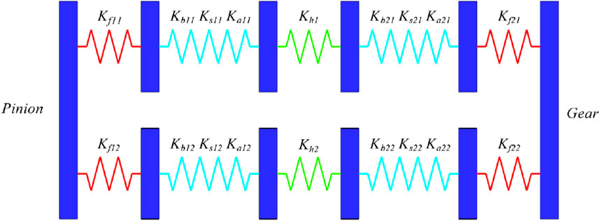
Figure 2. Gear mesh stiffness model.
The bending, axial compression, and shear stiffness components are computed by modeling the gear tooth of the involute spur gear as a cantilever beam with variable cross-section and an effective length
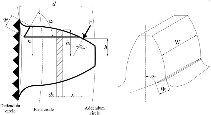
Figure 3. Model of the spur gear tooth as a non-uniform cantilever beam with a crack at tooth root.
The strain energy stored in a tooth due to bending, shear, and axial compression can be expressed as follows (Chaari et al., 2009; Sainsot And et al., 2004; Yang and Hu, 2022):
Here,
The strain energy stored in a meshing tooth can be determined based on beam theory using the following equations (Chaari et al., 2009; Sainsot And et al., 2004; Zou et al., 2023):
In these equations,
Based on Equations 1–3, the stiffnesses can be calculated as follows:
In Equations 4–6, the quantities
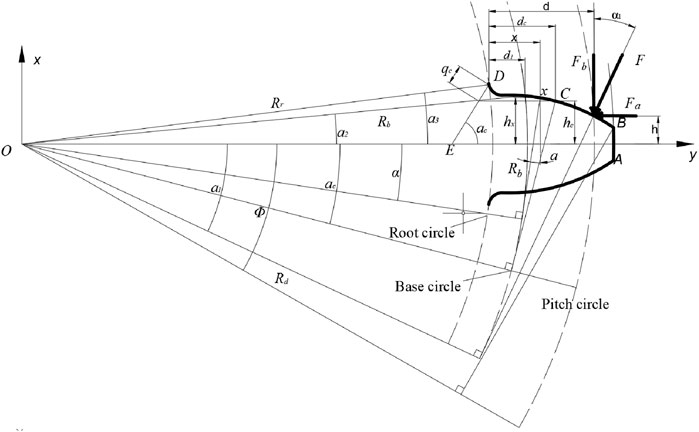
Figure 4. Schematic of a spur gear tooth.
Here,
According to the results of Yang and Sun (1985), the Hertzian contact stiffness between two meshing teeth is constant along the entire line of contact. It does not depend on the contact position or the contact depth. The Hertzian contact stiffness is given by Equation 10:
Besides tooth deformation, the reduction in the stiffness due to root deformation also affects the stiffness of the gear tooth. Sainsot And et al. (2004) derived a formula for calculating the deflection of the tooth foundation based on Muskhelishvili’s theory (Li and Lee, 2005). Subsequently, they applied this theory to a mixed elastic ring to derive an analytical formula reflecting the tooth deformation caused by the gear body, assuming that the stress varies linearly and is constant at the tooth root circle. We have Equation 11 (Yang and Sun, 1985; Radzevich, 2016):
Where:
Here:
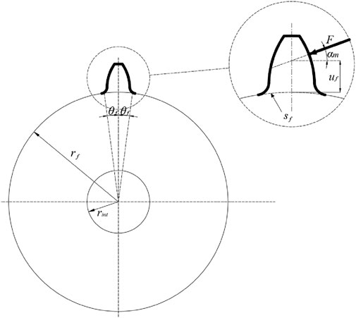
Figure 5. Geometrical parameters for the fillet-foundation deflection.
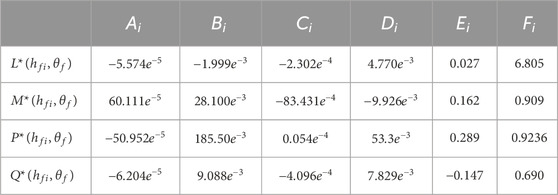
Table 1. The values for
and we also have the differential along the x direction given by Equation 15:
Where
Where
From these formulas, when calculating stiffnesses with respect to
2.3 Dynamic model of the gear system
A lumped parameter model of a multi-degree-of-freedom (multi-DOF) spur gear transmission system is established as shown in Figure 6. This model has been used to solve the vibration response problem of spur gears. Power is input by the driving gear
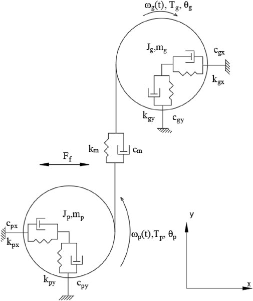
Figure 6. Scheme of spur gear system with six degrees of freedom.
The following model disregards instantaneous transmission error and other nonlinear factors. It incorporates a friction coefficient
Applying Newton’s second law and the moment balance equation, we obtain the system of equations in Equation 17 representing the 6 degrees of freedom in Figure 6 as:
Where:
Here,
Statistical features, which are commonly used to provide a measurement of the vibration level, are widely used in mechanical fault detection. In this paper, RMS and kurtosis indicators are also used to predict the severity of crack propagation. The RMS value is defined as given in Equation 19:
and Kurtosis is calculated by Equation 20:
3 Numerical simulation
In this section, we present the numerical simulation results from the six-degree-of-freedom gear dynamic model detailed in Section 2. Our main goal is to analyze the system’s vibrational response under various fault conditions. This analysis allows us to generate a high-quality synthetic dataset that accurately captures the dynamic signatures of these faults. This dataset is a crucial resource for training and validating AI/ML/DL-based fault diagnostic models, which are essential tools for proactive maintenance and operational efficiency in modern smart manufacturing environments.
3.1 Effect of root crack depth on gear mesh stiffness
Based on the analytical model presented in the previous section, the influence of crack depth on the mesh stiffness of a gear pair can be calculated and analyzed. The parameters of the gear pair used are listed in Table 2.
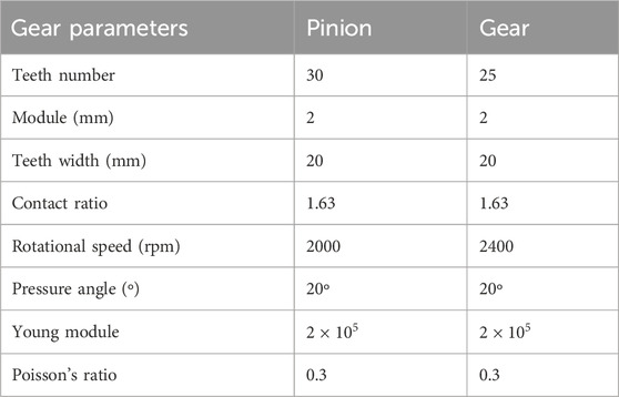
Table 2. Parameters of the pinion-wheel.
The total effective mesh stiffness of a gear pair, in the healthy case compared to the case where a crack appears on the tooth root with different depths, is presented in Figure 7. The total effective mesh stiffness is considered from the initial moment when the tooth with the crack at the root begins to mesh until this tooth disengages; the total mesh stiffness during this period is significantly affected by the presence of the crack, as can be observed in Figure 7 that the total mesh stiffness decreases when the crack appears, and the greater the depth of the crack, the lower the mesh stiffness.
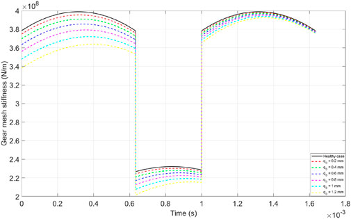
Figure 7. Mesh stiffness with different crack depth.
It can also be observed from Figure 7 that the phenomenon of stiffness reduction occurs most noticeably at the moment when the cracked tooth begins to mesh, and this can be observed more clearly in Figure 8 when we consider only the total mesh stiffness of a single tooth pair (including the cracked tooth) during the surveyed period. Figure 9 illustrates the reduction in average mesh stiffness during the meshing period of the surveyed tooth pair compared to a healthy tooth pair.
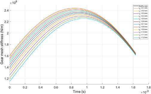
Figure 8. Mesh stiffness with different crack depth (single tooth pair).
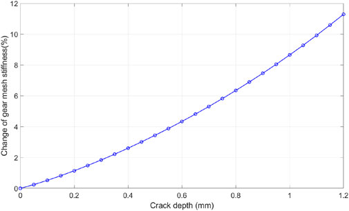
Figure 9. Change of mesh stiffness with different crack depth (single tooth pair).
3.2 Dynamic response
The design parameters of the spur gear system applied in this study are shown in Table 3. And this spur gear system operates under a load of 60 N m which is applied to the driven gear. The dynamic simulation was conducted under steady-state condition.
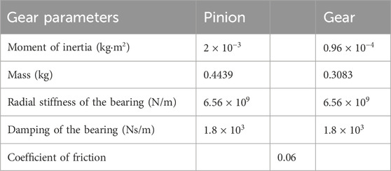
Table 3. Parameters of the gear system.
The analysis is conducted to study the changes in dynamic response characteristics due to the propagation of a tooth crack along its depth, while keeping the crack length and inclination angle constant (
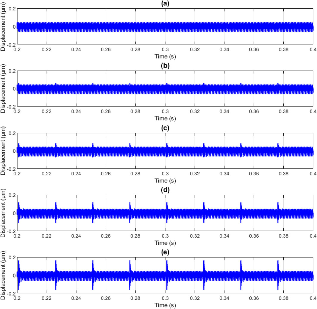
Figure 10. Displacement of pinion in y direction with crack length:15 mm,crack inclination angle:
The influence of gear tooth crack propagation along the tooth depth on frequency spectrum characteristics is also investigated Figure 11 displays the spectrum of the dynamic response of the pinion in the y-direction for the healthy case, while Figure 12 represents the case with a crack depth of 1.2 mm, and Figure 13 is a zoomed-in plot of Figure 12, providing information on how the tooth crack affects the sidebands around the mesh frequency and its harmonics. As suggested by Figures 11, 12, it can be concluded that the amplitudes at the first three harmonics of it are largely unaffected by the tooth crack. However, sidebands around the mesh frequency and its harmonics appear when a crack is present, which can be clearly observed in Figure 13. Observing the changes in the sidebands can provide more information on the presence and severity of the tooth crack.
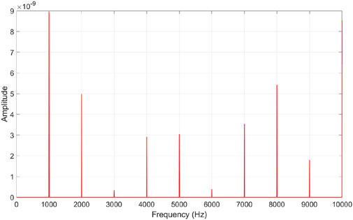
Figure 11. Spectrum of pinion vibration in y direction with crack depth
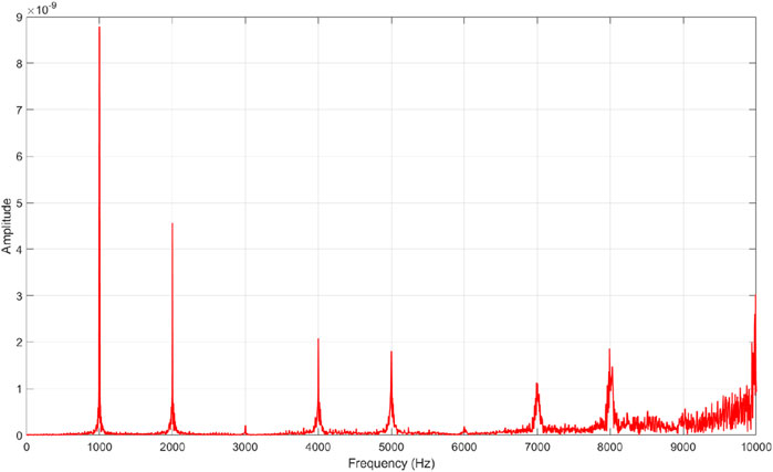
Figure 12. Spectrum of pinion vibration in y direction with crack depth
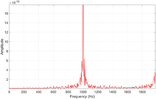
Figure 13. Magnified view of the dominant frequency peak of vibration with crack depth
The dynamic responses of the spur gear system are simulated. The displacements of the pinion in the y-direction with varying crack depths within the time range of 0.2–0.3 s under steady-state conditions are shown in Figure 10. It is very difficult to observe changes in the displacement waveform caused by the tooth root crack when it is in its early stage. However, multiple distinct impulses appear when the crack propagates to a certain degree. The time interval between two adjacent impulses is exactly equal to the rotational period of the pinion, which is 60/2400 = 0.025 s.
The statistical indicators RMS and kurtosis are used to assess the severity of the crack in the tooth root, and the curves showing the trends of these two indicators with respect to the depth of the crack are shown in Figure 14, As the crack in the tooth spreads along the depth of the tooth, RMS appears to vary linearly with the depth of the crack, while kurtosis exhibits a sudden increase when the crack reaches a severe level, seemingly following a quadratic trend with the depth of the crack. Changes in the statistical indicators due to the propagation of the tooth crack can be useful for gear fault diagnosis and condition monitoring.
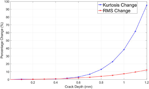
Figure 14. Change of statistical indicators along crack depth.
4 Conclusion
This study presented a detailed analysis of the dynamic response and meshing stiffness modeling of spur gears with root cracks. As core power transmission components in most mechanical systems, from industrial to military applications, gearboxes are susceptible to faults such as wear, pitting, and particularly tooth cracks. These faults can lead to dynamic instability, catastrophic failures, and significant economic losses. Therefore, early and accurate fault diagnosis is crucial to ensure reliability and operational efficiency, especially within the rapidly evolving landscape of Smart Manufacturing and Industry 4.0.
In this research, we proposed a strain energy-based method to accurately model the time-varying meshing stiffness (TVMS) of cracked spur gear pairs. This model meticulously accounts for factors such as the crack’s depth, orientation, and propagation along the entire tooth width, along with bending, axial, shear, and tooth-foundation deformations. Based on this stiffness formulation, a six-degree-of-freedom lumped-parameter dynamic model was developed to simulate the vibrational response of the gear system under various fault conditions, using the time-varying gear mesh damping that was calculated based on the time-varying meshing stiffness of the gear pair.
The numerical simulation results indicated that crack propagation leads to a significant reduction in meshing stiffness and generates distinct impulsive responses in the vibration signal. Statistical features like RMS and Kurtosis were shown to be sensitive to crack depth, with both metrics increasing as the crack grows. Notably, the presence of a crack also resulted in the appearance of sidebands and their harmonics around the meshing frequency, providing crucial information about the fault’s presence and severity.
Importantly, the detailed dynamic modeling results and simulated data obtained from this study serve as an essential foundation for generating high-quality synthetic fault data. This is a prerequisite for training and optimizing Artificial Intelligence (AI), Machine Learning (ML), and Deep Learning (DL) models in fault diagnosis and condition monitoring applications. Leveraging simulated data is particularly vital for overcoming the scarcity of real-world experimental fault data in complex operational environments, which is a key bottleneck in the deployment of AI-based diagnostic methods. This approach contributes to building a robust framework for Digital Twin systems, enabling precise monitoring and predictive maintenance in smart manufacturing.
Although the current model focuses on spur gears with cracks uniformly distributed across the tooth width, the insights gained into stiffness degradation and dynamic characteristics provide a solid theoretical basis. Future research will focus on developing stiffness analysis models for more complex crack distributions and different types of gears. Simultaneously, further studies are needed to more deeply integrate these physical models with advanced AI/ML/DL algorithms to enhance model interpretability, handle imbalanced datasets, and accelerate the implementation of automated, intelligent, and real-time fault diagnosis systems in industrial settings.
Data availability statement
The original contributions presented in the study are included in the article/supplementary material, further inquiries can be directed to the corresponding authors.
Author contributions
P-DN: Writing – review and editing, Writing – original draft, Project administration, Conceptualization, Supervision. T-DP: Visualization, Conceptualization, Validation, Writing – review and editing, Software, Resources, Writing – original draft. D-T-BD: Conceptualization, Investigation, Writing – review and editing, Software, Formal Analysis, Writing – original draft, Visualization, Data curation. J-WL: Writing – review and editing, Supervision, Project administration, Visualization, Resources, Funding acquisition, Validation. T-DN: Formal Analysis, Data curation, Writing – review and editing, Writing – original draft.
Funding
The author(s) declare that financial support was received for the research and/or publication of this article. This research is supported by Intelligent Technical Diagnostics Lab. Suggestions and comments from the reviewers and the editor are very much appreciated.
Conflict of interest
The authors declare that the research was conducted in the absence of any commercial or financial relationships that could be construed as a potential conflict of interest.
Generative AI statement
The author(s) declare that no Generative AI was used in the creation of this manuscript.
Any alternative text (alt text) provided alongside figures in this article has been generated by Frontiers with the support of artificial intelligence and reasonable efforts have been made to ensure accuracy, including review by the authors wherever possible. If you identify any issues, please contact us.
Publisher’s note
All claims expressed in this article are solely those of the authors and do not necessarily represent those of their affiliated organizations, or those of the publisher, the editors and the reviewers. Any product that may be evaluated in this article, or claim that may be made by its manufacturer, is not guaranteed or endorsed by the publisher.
References
Bartelmus, W. (2001). Mathematical modelling and computer simulations as an aid to gearbox diagnostics. Mech. Syst. Signal Process. 15, 855–871. doi:10.1006/mssp.2001.1411
Chaari, F., Fakhfakh, T., and Haddar, M. (2009). Analytical modelling of spur gear tooth crack and influence on gearmesh stiffness. Eur. J. Mechanics-A/Solids 28, 461–468. doi:10.1016/j.euromechsol.2008.07.007
Gauder, D., Gölz, J., Jung, N., and Lanza, G. (2023). Development of an adaptive quality control loop in micro-production using machine learning, analytical gear simulation, and inline focus variation metrology for zero defect manufacturing. Comput. Industry 144, 103799. doi:10.1016/j.compind.2022.103799
Gecgel, O., Ekwaro-Osire, S., Dias, J. P., Nispel, A., Alemayehu, F. M., and Serwadda, A. (2018). “Machine learning in crack size estimation of a spur gear pair using simulated vibration data,” in International conference on rotor dynamics (Springer), 175–190.
Howard, I., Jia, S., and Wang, J. (2001). The dynamic modelling of a spur gear in mesh including friction and a crack. Mech. Syst. signal Process. 15, 831–853. doi:10.1006/mssp.2001.1414
Iida, H., Tamura, A., and Yamada, Y. (1985). Vibrational characteristics of friction between gear teeth. Bull. JSME 28, 1512–1519. doi:10.1299/jsme1958.28.1512
Kahraman, A., and Singh, R. (1991). Interactions between time-varying mesh stiffness and clearance non-linearities in a geared system. J. Sound Vib. 146, 135–156. doi:10.1016/0022-460x(91)90527-q
Koutsoupakis, J., Seventekidis, P., and Giagopoulos, D. (2023). Machine learning based condition monitoring for gear transmission systems using data generated by optimal multibody dynamics models. Mech. Syst. Signal Process. 190, 110130. doi:10.1016/j.ymssp.2023.110130
Kumar, A., Sankar, T., and Osman, M. (1985). On dynamic tooth load and stability of a spur-gear system using the state-space approach, 107, 54, 60. doi:10.1115/1.3258695
Li, C. J., and Lee, H. (2005). Gear fatigue crack prognosis using embedded model, gear dynamic model and fracture mechanics. Mech. Syst. signal Process. 19, 836–846. doi:10.1016/j.ymssp.2004.06.007
Liu, X., Huang, H., and Xiang, J. (2020). A personalized diagnosis method to detect faults in gears using numerical simulation and extreme learning machine. Knowledge-Based Syst. 195, 105653. doi:10.1016/j.knosys.2020.105653
Liu, Z., Chang, C., Hu, H., Ma, H., Yuan, K., Li, X., et al. (2024). Dynamic characteristics of spur gear system with tooth root crack considering gearbox flexibility. Mech. Syst. Signal Process. 208, 110966. doi:10.1016/j.ymssp.2023.110966
Liu, Y., Shan, Z., Liang, H., Sun, Q., and Ma, H. (2025). A review of dynamics-based failure modeling and diagnosis techniques for gear systems. Mech. Mach. Theory 215, 106166. doi:10.1016/j.mechmachtheory.2025.106166
Ma, R., Chen, Y., and Cao, Q. (2012). Research on dynamics and fault mechanism of spur gear pair with spalling defect. J. Sound Vib. 331, 2097–2109. doi:10.1016/j.jsv.2011.12.010
Radzevich, S. P. (2016). Dudley’s handbook of practical gear design and manufacture. Boca Raton, FL: CRC Press.
Sainsot And, P., Velex, P., and Duverger, O. (2004). Contribution of gear body to tooth Deflections—A new bidimensional analytical formula. J. Mech. Des. 126, 748–752. doi:10.1115/1.1758252
Sakai, T., Doi, Y., Yamamoto, K.-i., Ogasawara, T., and Narita, M. (1981). Theoretical and experimental analysis of rattling noise of automotive gearbox. Tech. Rep. SAE Tech. Pap. 1, 810773. doi:10.4271/810773
Sharma, G., Kaur, T., Mangal, S. K., and Kohli, A. (2024). Investigating bearing and gear vibrations with a micro-electro-mechanical systems (mems) and machine learning approach. Results Eng. 24, 103499. doi:10.1016/j.rineng.2024.103499
Srivastava, A., and Tiwari, R. (2025). Development of a digital model of a gear rotor system for fault diagnosis using the finite element method and machine learning. J. Dyn. Monit. Diagnostics 4, 121–136. doi:10.37965/jdmd.2025.806
Tordion, G., and Gauvin, R. (1977). Dynamic stability of a two-stage gear train under the influence of variable meshing stiffnesses, 99, 785, 791. doi:10.1115/1.3439314
Van Khang, N., Cau, T. M., and Dien, N. P. (2004). Modelling parametric vibration of gear-pair systems as a tool for aiding gear fault diagnosis. Tech. Mechanik-European J. Eng. Mech. 24, 198–205.
Wang, H., Yang, R., and Xiang, J. (2022). Numerical simulation of gears for fault detection using artificial intelligence models. Measurement 203, 111898. doi:10.1016/j.measurement.2022.111898
Yang, D., and Sun, Z. (1985). A rotary model for spur gear dynamics. J. Mech. Transm. automation Des. 107, 529–535. doi:10.1115/1.3260759
Yang, N. C. Z. H. J. Z. L., Hu, Y., Cheng, Z., Hu, J., and Zhang, L. (2022). Improved mesh stiffness method and vibration analysis of a planetary gear system with a spatial tooth crack. Machines 10, 1168. doi:10.3390/machines10121168
Yu, J., Wang, H., and Ren, D. (2023). Chaos analysis of single-stage spur gear system considering backlash fractal. J. Vib. Eng. and Technol. 11, 3481–3491. doi:10.1007/s42417-022-00762-y
Keywords: predictive maintenance, smart manufacturing, gear mesh stiffness, tooth crack, numerical simulation
Citation: Nguyen P-D, Pham T-D, Do D-T-B, Liang J-W and Nguyen T-D (2025) Strain energy-based gear mesh stiffness modeling and synthetic data generation for AI-driven fault diagnosis in smart manufacturing. Front. Mech. Eng. 11:1682102. doi: 10.3389/fmech.2025.1682102
Received: 08 August 2025; Accepted: 22 October 2025;
Published: 11 November 2025.
Edited by:
Lien Thi Vu, Phenikaa University, VietnamReviewed by:
Nguyen Nga, Thai Nguyen University, VietnamBai Xiaoning, Henan Polytechnic University, China
Copyright © 2025 Nguyen, Pham, Do, Liang and Nguyen. This is an open-access article distributed under the terms of the Creative Commons Attribution License (CC BY). The use, distribution or reproduction in other forums is permitted, provided the original author(s) and the copyright owner(s) are credited and that the original publication in this journal is cited, in accordance with accepted academic practice. No use, distribution or reproduction is permitted which does not comply with these terms.
*Correspondence: Trong-Du Nguyen, ZHUubmd1eWVudHJvbmdAaHVzdC5lZHUudm4=; Jin-Wei Liang, bGlhbmdqQG1haWwubWN1dC5lZHUudHc=