 Jianping Zuo
 Qingqing Chai2
- 1School of Mechatronics and Information Engineering, Chongqing College of Humanities, Science & Technology, Chongqing, China
- 2Automotive Technical Department, Chongqing Telecommunications Polytechnic College, Chongqing, China
- 3Design Academy, Sichuan Fine Arts Institute, Chongqing, China
Introduction: The long charging cycle, limited energy storage system, and short range of traditional batteries have constrained the further development of electric vehicles.
Methods: Given this, the paper constructs a regenerative braking control strategy for electric vehicles based on hierarchical fuzzy control, and optimizes it using an improved Particle Swarm Optimization (PSO) algorithm. The study aims to improve the energy recovery efficiency of electric vehicles while ensuring the safety and stability of vehicle braking by reasonably allocating motor and hydraulic braking forces.
Results: The results showed that the improved PSO exhibited faster convergence speed and higher accuracy in the optimization process, with the smallest difference in optimal solutions and the lowest loss function value of 10−5. In terms of regenerative braking control effect of electric vehicles, the control strategy built on improved PSO achieved an energy recovery rate of 16.8% and increased the contribution of driving range by 35 km. Its braking response time has been shortened to 0.71 s, the braking stability index has reached 95, and the energy consumption rate has been reduced to 150 Wh/km.
Discussion: The proposed hierarchical fuzzy control strategy based on improved PSO provides an efficient and stable solution for the design and optimization of regenerative braking systems in electric vehicles. This optimization scheme can enhance the energy utilization efficiency and endurance of electric vehicles, which is of great significance for promoting the development of electric vehicle technology.
1 Introduction
Electric Vehicles (EVs) have become an important development direction in the future transportation industry due to their advantages such as zero emissions and low noise. However, EVs still face many challenges in their development process. Traditional batteries have long charging cycles and limited energy storage system capacity, making it difficult for EVs to meet long-distance driving needs (Beşkardeş et al., 2024; Re et al., 2023). In addition, as a key technology to improve the Energy Utilization Efficiency (EUE) of EVs, the performance optimization of the Braking Energy Recovery (BER) system has always been a hot and difficult research topic. The continuous development of EVs technology has led to the continuous expansion of its market size, but the issue of range is still one of the key factors restricting its widespread application. The range of EVs depends on the energy density of the battery and is also closely correlated with the efficiency of BER system. The Regenerative Braking System (RBS) recovers energy during vehicle deceleration, converts it into electrical energy, and stores it in the battery, thereby extending the range of EVs. However, the current RBS still has shortcomings in Energy Recovery Efficiency (ERE) and braking performance, especially in terms of adaptability and stability under different operating conditions, which still need further improvement (Luo et al., 2024; Bingül and Yıldız, 2023). In the research of RBS in EVs, the optimization of control strategy is crucial. Traditional Regenerative Braking Control (RBC) strategies are mostly based on a single control algorithm, such as fuzzy logic control, neural networks, or model predictive control. These methods have improved ERE to some extent, but in complex operating conditions, it is often difficult to achieve optimal braking force distribution and energy recovery. Particle Swarm Optimization (PSO) is widely utilized in the optimization of RBC strategies for EVs since its efficient global search ability and fast convergence characteristics (Abd-Elhaleem et al., 2023; Pukkunnen et al., 2023).
In recent years, with the widespread application of EVs, their energy recovery and RBC strategy research have gradually become hot topics, and many scholars have conducted in-depth research on this issue. To solve the problems of long charging cycles, energy storage system limitations, and short range of EVs in traditional batteries, Chai et al. proposed a proportional-integral-controller method based on PSO algorithm. Compared with traditional methods, PSO-based energy management methods could achieve higher energy efficiency. This method increased the total driving distance of EVs by 6%, the maximum and peak speeds by 3.9%, and the average speed by 14.5% (Chai et al., 2022). To recover more braking energy while ensuring vehicle safety, Zhang et al. proposed an RBC strategy based on swarm intelligence prediction. This strategy adopted PSO as the main part, used ACO to improve the iterative process of PSO, avoided getting stuck in local optimal solutions, and applied model predictive control theory to achieve optimal control. Through simulation experiments, the stability and economy of the proposed strategy were tested under emergency braking and urban cycling conditions (Zhang et al., 2022). To improve the regenerative braking energy of EVs and the driving interval of vehicles, Saiteja et al. proposed various control architectures and main braking methods. This study reviewed the main subsystems of RBS in EVs and how they affect braking performance. It also systematically reviewed several RBC strategies including fuzzy logic control, neural networks, and model predictive control. In addition, the design process of RBS and its calibration variables, including vehicle velocity and braking force assessment, were also discussed, which could be utilized to lift braking performance (Saiteja et al., 2022). Ratchanyaraj and Ravindran proposed a method combining Improved Fractional-Order Darwinian PSO (IFODPSO) and fuzzy logic controller to optimize motor performance in RBC of EVs. The IFODPSO method outperformed traditional techniques in torque control. In addition, the fuzzy estimation could improve system efficiency at low speeds (Ratchanyaraj and Ravindran, 2024). To solve the problems of improving the motion performance and controlling the handling stability of distributed drive electric vehicles, Guo N et al. evaluated the driving state and generated a unified yaw velocity reference through a motion monitor that only relies on the feedback of the front wheel steering Angle. The direct yaw moment control is achieved by adopting the nonlinear model predictive control strategy based on Lyapunov, and the contraction constraint is added to ensure the closed-loop stability and provide a rigorous proof. Develop and improve the iterative linear quadratic regulator algorithm, combine the relaxed logarithmic obstacle function and the double-loop iterative processing of inequality constraints, and supplement with the auxiliary control law to generate the initial solution to reduce sensitivity. Simulation and hardware-in-the-loop experiments show that this strategy has better manipulation stability and higher computational efficiency (Guo et al., 2025). To address the optimization and real-time performance issues of energy management in fuel cell plug-in hybrid vehicles, Zhang W et al. proposed a predictive energy management strategy based on the Pontriagin minimum principle and costate boundary. The costate boundary range is determined in real time based on the feedback information. A heuristic rule for online iterative calibration of costates and an analytical method for finding the optimal solution of the Hamiltonian function are also proposed. Simulation and hardware-in-the-loop experiments show that this strategy can efficiently update costates, smooth control instructions, achieve expected state of charge tracking, improve fuel economy, and the sampling time in hardware-in-the-loop testing is short, making it applicable in real time (Guo et al., 2024). To solve the problem of performance improvement of the regenerative braking system of traditional electric vehicles, Valladolid J D et al. proposed an auxiliary control strategy. This strategy utilizes experimental data and a linear model for vehicle dynamics estimation, combined with the concept of model predictive control, to compensate for the target torque provided by the integrated brake assist unit and pressure source unit. The simulation was carried out through MATLAB/Simulink software, and the results show that the proposed auxiliary braking torque controller is effective (Valladolid and Macas, 2023).
In summary, most existing studies only use PSO algorithm for parameter optimization, without fully considering its combination with other control algorithms, resulting in certain limitations in practical applications. There is still a certain research gap on how to achieve optimal braking force distribution under different operating conditions and how to further improve motor performance optimization. To overcome the constrains of existing research and further improve the EUE and endurance of EVs, this study adopts a Hierarchical Fuzzy Control (HFC) method to construct an EV-RBC strategy and applies an improved PSO to optimize it. The innovation points and contributions of the research are as follows:
1. Algorithm integration and innovation: For the first time, HFC and the improved PSO algorithm are deeply combined to form a complete technical path of control strategy construction - parameter optimization and upgrade, providing an efficient and stable new solution for the regenerative braking control strategy of electric vehicles and making up for the limitations of single algorithm application in existing research.
2. Innovation in braking force distribution mechanism: The HFC strategy achieves refined braking force distribution through a two-layer architecture design. The first layer rationally distributes the braking force of the front and rear axles based on the total braking force required by the entire vehicle. The second layer redistributes the braking force of the front axle according to the braking intensity, ensuring the braking stability of the vehicle while maximizing the energy recovery efficiency under different braking conditions.
3. Innovation in performance optimization of PSO Algorithm: By adjusting the particle update rule and inertia weight to improve the traditional PSO algorithm, a nonlinear function is introduced to control the ratio of individual extremum to global extremum, replacing the original random coefficient to enhance the algorithm’s optimization accuracy. The inertia weight is calculated by using a nonlinear inertia function to achieve a dynamic balance between global optimization and local optimization, further enhancing the parameter optimization capability of the fuzzy control system, thereby more efficiently improving the regenerative braking energy recovery efficiency and system stability.
The first part of the article serves as the introduction, elaborating on the development advantages of electric vehicles in terms of zero emissions and low noise, pointing out the shortcomings of traditional batteries, sorting out the limitations of the single algorithm in the existing regenerative braking control strategies, and proposing the idea and innovative direction of adopting the HFC construction strategy and combining it with the improved PSO optimization. The second part is about methods and materials, introducing the regenerative braking control method for electric vehicles based on HFC, elaborating on the particle initialization, position-velocity update rules, nonlinear function and inertia weight improvement methods and optimization processes of the improved PSO. The third part is the results, comparing the performance of the improved PSO in terms of the optimal solution, convergence speed, etc. Compare the regenerative braking index performance of different algorithms and analyze the performance differences of the strategies under urban, suburban and high-speed working conditions. The fourth part is the conclusion, summarizing the improvement effects of the strategy in terms of energy recovery rate, driving range and braking performance, and pointing out the shortcomings and future directions under high-speed working conditions.
2 Methods and materials
This study develops a RBC method for EVs. This method is based on HFC technology and adjusted with the help of optimized PSO. The HFC scheme maximizes ERE and guarantees the safety of the car braking process through precise braking force distribution between the hydraulic and motor braking system. The improved PSO algorithm further enhances the efficiency of BER and improves the stability and adaptability of the system by adjusting particle update rules and inertia weights.
2.1 RBC method for EVs based on HFC
This study uses HFC technology for EV-RBC strategy to improve the ERE during braking and ensure the reliability of service braking. This scheme divides RBC into a dual layer structure through a hierarchical architecture design: The primary level completes the reasonable distribution of braking force between the front and rear axles based on the overall braking force required by the vehicle; The second layer distributes the Front Axle Braking Force (FABF) twice based on the braking intensity to adapt to different braking conditions. The power system of EVs mainly includes a drive motor, a power battery, a transmission system, and a braking system. The driving motor transmits power to the wheels through the transmission system, achieving the driving of the car. The braking system recovers energy when the vehicle decelerates, converts kinetic energy into electrical energy through electric motor generation, and stores it in the power battery (Zhou et al., 2023; Nandakumar, 2024), as shown in Figure 1.
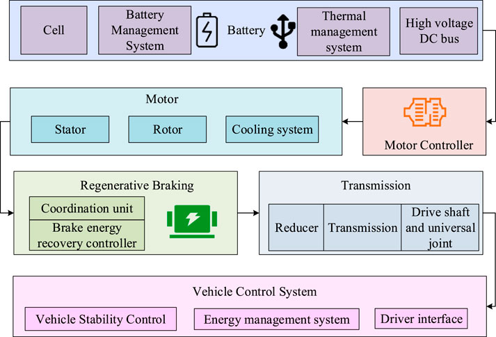
Figure 1. Structure diagram of EV power system.
In Figure 1, the system includes a battery, motor, motor controller, transmission system, BER system, and vehicle control system. The battery section includes battery cells, battery and thermal management systems, and high-voltage DC bus. The motor part consists of a stator and a rotor, and is equipped with a cooling system. The motor controller is responsible for controlling the operation of the motor. The transmission system includes a reducer, transmission device, drive shaft, and universal joint. BER system recovers energy during vehicle deceleration through a BER controller and manages energy flow through coordination units. The vehicle control system includes vehicle stability control, energy management, and driver interface, responsible for the operation control and energy allocation of the entire vehicle. The braking system model adopted in the research is the cooperative control relationship of motor braking and hydraulic braking. When a vehicle brakes, the motor braking system first exerts force within its torque limit to prioritize energy recovery, while the hydraulic braking system compensates for the remaining required braking force in real time. The two are dynamically coordinated through the vehicle controller to avoid conflicts caused by superimposed or insufficient braking force, ensuring a smooth and shock-free braking process. To quantitatively evaluate the effect of motor energy recovery, the motor efficiency relationship is introduced. Motor efficiency is defined as the ratio of the electrical energy output by the motor in the power generation mode to the mechanical energy input by the wheel. Based on the EM150 motor experiment selected in the research, it is fitted as a binary function of the motor speed and torque, as shown in Equation 1.
In Equation 1,
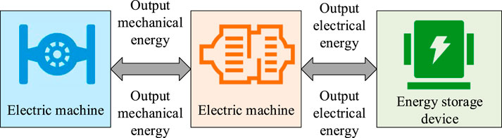
Figure 2. Process diagram of regenerative braking.
In Figure 2, when the vehicle requires power, the driving motor drives the vehicle in the form of outputting mechanical energy. When braking, the driving motor switches to the power generation mode, converting the car’s kinetic energy into electrical energy and storing it in the power battery. During this process, the reasonable distribution of MBF and HBF is used to maximize energy recovery, thereby improving the EUE and driving range of EVs. The EV-RBC strategy based on HFC is shown in Figure 3.
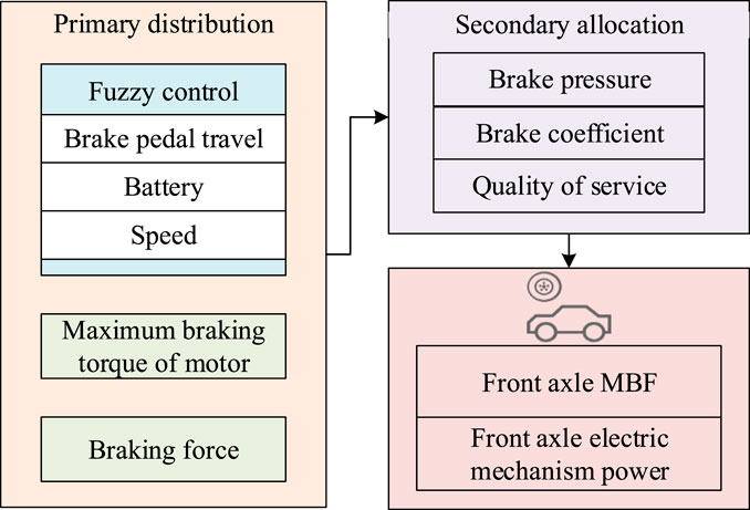
Figure 3. Diagram of RBC for EVs based on HFC.
In Figure 3, the distribution scheme of FABF and Rear Axle Braking Force (RABF) is first calculated grounded on the braking force needed by the whole vehicle. The RABF is further divided into RABF and rear axle Mechanical Braking Force (MBF). The FABF is determined through primary and secondary distribution: the primary distribution is determined by a fuzzy controller based on input variables including brake pedal travel, battery, and car speed; The secondary allocation is further divided into three situations built on the braking intensity: mild, moderate, and emergency braking, corresponding to the MBF of the front axle and the braking force of the front axle motor. Among them, the membership function of the fuzzy logic controller adopts a mixed set of triangular and Gaussian types: for the three continuous input variables of brake pedal travel, battery state of charge, and vehicle speed, the middle intervals of the variables use triangular membership functions, taking advantage of their simplicity in calculation and fast response speed. The variable boundary intervals adopt Gaussian membership functions to reduce the sensitivity to extreme value fluctuations and avoid sudden changes in control output. The membership function of each input variable is divided into three language levels: low, medium and high. Together, they form a 3 × 3 × 3 rule base, which contains 27 control rules, achieving precise mapping from the input variable to the braking force distribution ratio of the front axle.
To ensure braking safety, the vehicle dynamics I-J braking constraint is introduced: I represents the front axle braking force distribution coefficient, reflecting the proportion of the front axle braking force to the total braking force of the vehicle; J represents the utilization rate of the adhesion coefficient, reflecting the degree to which the total braking force utilizes the maximum adhesion capacity of the road surface. This constraint requires that the actual braking force distribution point must fall within the stable area enclosed by the I curve and the J curve, ensuring that both the front and rear axle wheels simultaneously reach the adhesion limit during braking, avoiding vehicle loss of control caused by single-axle wheel locking, and guaranteeing the stability of the braking direction.
In addition, the braking strength is determined by parameters such as braking pressure, braking coefficient, and vehicle mass to ensure optimal braking force distribution and energy recovery under different braking conditions (Shu, 2025). The required braking force of the entire vehicle is calculated from the brake pedal travel signal, multiplied by the FABF and RABF distribution coefficients to obtain the required braking force of the front and rear axles, as shown in Equation 2.
In Equation 2,
In Equation 3,
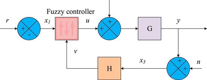
Figure 4. Structure design drawing of fuzzy controller.
In Figure 4, the controller processes the input signal through fuzzy logic and generates control output
In Equation 4,
2.2 EV-RBC strategy optimization based on improved PSO
After proposing the HFC-based EV-RBC strategy, this study further focuses on optimizing the performance of the control strategy. Therefore, an improved PSO has been introduced to more effectively improve the ERE and system stability of regenerative braking. The improved PSO achieves a more effective balance between global and local optima by adjusting particle update rules and inertia weights, thereby improving the convergence and resolution quality of the algorithm (Suyambu and Vishwakarma, 2023; Azim et al., 2024; Heydari et al., 2023). This algorithm optimizes the core variables of the fuzzy logic controller, specifically including the characteristic parameters of the fuzzy membership function (the vertex coordinates of the triangular membership function, the mean and standard deviation of the Gaussian membership function) and the output weights of the fuzzy rule base. The optimization objective is set to minimize the regenerative braking energy loss rate and the fluctuation of vehicle braking deceleration, while maximizing the motor energy recovery efficiency. The constraints include: The parameters of the fuzzy membership function should be within a physically reasonable range, and the output weights of the fuzzy rules should meet the 0–1 normalization requirement. During the optimization process, the braking intensity z should always be within 0–1.5 to avoid exceeding the physical limit of the vehicle braking system. The motor torque needs to be controlled within the range of the rated torque (180 Nm) and peak torque (300 Nm) of the EM150 motor. The improved PSO first initializes the position and speed of the PSO. The calculation of the initial position and particle velocity is shown in Equation 5.
In Equation 5,
In Equation 6,
In Equation 7,
In Equation 8,
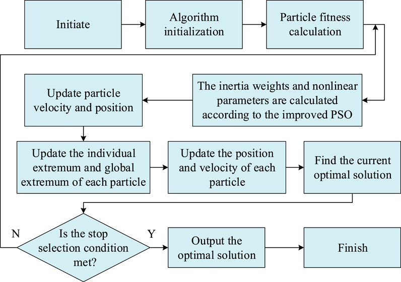
Figure 5. Flowchart for improving PSO.
In Figure 5, the algorithm is first initialized, including the initial position and velocity of randomly generated particles. Subsequently, fitness calculations are performed on each particle to evaluate its performance in optimization problems. On this basis, the algorithm calculates inertia weights and nonlinear parameters based on improved PSO rules to enhance dynamic balance during the search process. Next, it enters the particle update phase, where the velocity and location of each particle are updated sequentially, while also updating the individual and global optimal positions of the particles. After each iteration, the algorithm checks whether the preset stopping conditions are met. If the maximum NoI or the accuracy of the solution is reached, it indicates that the requirements are met (Mohammad and Jaber, 2022; Hasan et al., 2023). The optimization process of EV-RBC strategy based on improved PSO is exhibited in Figure 6.
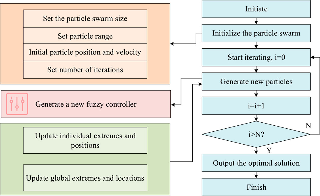
Figure 6. Optimization flowchart of EV-RBC strategy based on improved PSO.
In Figure 6, during the start-up phase, it is necessary to determine the size of the PSO, the activity range of particles, and the NoI in the loop, and to set the initial position and motion rate of the PSO. The next step is to start the iteration process, starting from the iteration counter
3 Results
This study evaluated the performance of a fuzzy control system based on improved PSO through a series of experiments, verifying its optimization effect in EVs regenerative braking. At the same time, a comparative analysis was conducted on the RBC effects of different algorithms under various operating conditions, comprehensively examining key indicators such as Energy Recovery Rate (ERR), braking response time, braking stability index, and energy consumption rate. The purpose was to reveal the impact of different algorithms and operating conditions on the regenerative braking performance of EVs.
3.1 Performance evaluation of fuzzy control system based on improved PSO
To comprehensively evaluate the performance of the fuzzy control system built on improved PSO in regenerative braking of EVs, a series of performance evaluation experiments are designed. These experiments will test and validate the fuzzy control system through precisely set parameters and configurations. Table 1 shows the experimental setup.
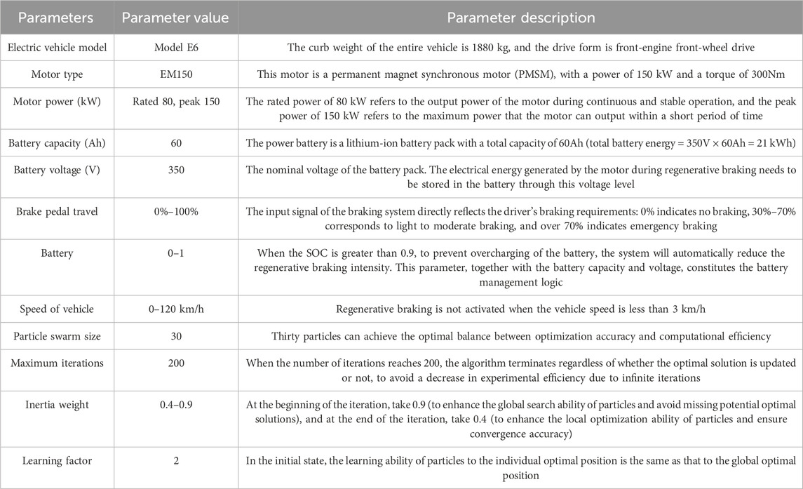
Table 1. Experimental parameters.
In Table 1, the EV model is selected as Model E6. This model has a typical EVs powertrain configuration, including a front mounted Permanent Magnet Synchronous Motor (PMSM) with a maximum power of 150 kW and a maximum torque of 300 Nm. The power battery is a lithium-ion battery with a total capacity of 60Ah and a nominal voltage of 350V. The battery management system is in charge of the management of battery charging and discharging, as well as temperature control. The driving motor is PMSM, with a rated power of 80 kW, a peak power of 150 kW, motor torque rating 180 Nm, peak 300 Nm. A rated speed of 3000 rpm corresponds to a rated power of 80 kW, and a peak speed of 6000 rpm is suitable for a peak power of 150 kW. The input parameters of the fuzzy control unit include the displacement of the brake pedal, battery status, and car speed, and its output result is the proportion of MBF distribution. The fuzzy controller’s membership function adopts triangular and Gaussian types, and the rule library contains 27 rules. The PSO scale is 30, the maximum NoI is 200, the inertia weight varies linearly between 0.4 and 0.9, and the learning factors c1 and c2 are both set to 2. Under the improved PSO control, the motor braking torque response delay is only 80 m. It can smoothly rise from 0 to 120 Nm (66.7% of the rated torque) within 0.2 s after braking trigger, and the torque fluctuation range is controlled within ±5 Nm. The motor’s power generation capacity simultaneously rose from 0 to 35 kW (48.6% of the peak power), with no obvious peak impact on the power curve. The continuous stable output time accounted for more than 85% of the braking process. The improved PSO is compared with PSO, Simulated Annealing (SA), and Grey Wolf Optimizer (GWO). The optimal solution statistics of several algorithms are shown in Figure 7.
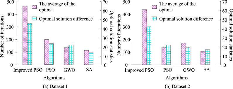
Figure 7. Statistical values of optima of several algorithms. (a) Dataset 1; (b) Dataset 2.
In Figure 7a, the improved PSO achieves the average optima after about 100 iterations, with the least NoI and the smallest difference in optima, which is about 10. PSO reaches the average optima after about 200 iterations, with a difference of about 15 in optima. GWO reaches the average optima after about 150 iterations, with a difference of approximately 12 optima. SA has the least NoI, about 100, but the maximum difference in optima is about 20. In Figure 7b, the improved PSO also shows the minimum NoI, about 100, and the optima difference is the smallest, about 5. The PSO iteration reaches the average optima about 200 times, with a difference of about 10 in the optima. GWO reaches the average solution after about 150 iterations, with an optima difference of approximately 8. SA has the least NoI, about 100, but the maximum difference in optima is about 15. The improved PSO shows the fastest convergence speed and the smallest difference in optima on both datasets, demonstrating its efficiency and accuracy in optimizing problems. The accuracy and recall of several algorithms are shown in Figure 8.
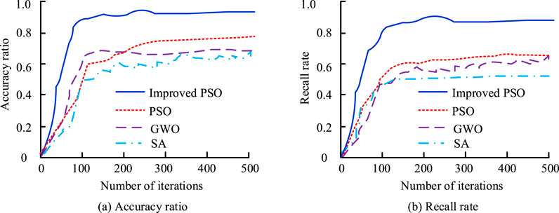
Figure 8. Accuracy and recall rates of several algorithms in optimizing fuzzy control system parameters. (a) Accuracy ratio; (b) Recall rate.
In Figure 8a, the improved PSO quickly achieves high accuracy with fewer iterations and tends to stabilize after about 100 iterations, with a final accuracy close to 0.98. In Figure 8b, the improved PSO also quickly achieves a high recall rate with fewer iterations and stabilizes after about 100 iterations, with a final recall rate close to 0.95. Improved PSO exhibits faster convergence speed and higher accuracy and recall during the iteration process, demonstrating its superior performance in optimizing problems. The loss function values of several algorithms are shown in Figure 9.
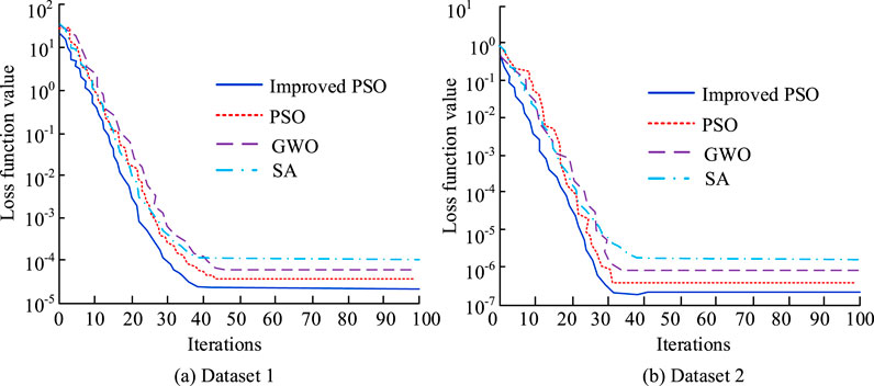
Figure 9. Loss function values of several algorithms. (a) Dataset 1; (b) Dataset 2.
In Figure 9a, PSO rapidly reduces the loss function value when the NoI is small, showing a fast convergence speed, and reaches the lowest loss function value at the end of the iteration, which is about 10−5. The convergence speed of PSO, GWO, and SA is relatively slow, with PSO stabilizing after about 40 iterations and GWO and SA stabilizing after about 60 iterations. In Figure 9b, the improved PSO also demonstrates the fastest convergence speed, reaching the lowest loss value of approximately 10−6 after about 30 iterations. The improved PSO demonstrates superior convergence performance on both datasets, with fast convergence speed and the lowest final loss function value, demonstrating higher efficiency and accuracy in optimizing problems.
3.2 Evaluation of RBC effect of EVs based on improved PSO
After verifying the performance of the improved PSO, this study evaluates the RBC effect of EVs based on the improved PSO. To comprehensively understand the performance of different algorithms under different operating conditions, a detailed performance comparison analysis is conducted on the improved PSO, PSO, SA, and GWO, as listed in Table 2.
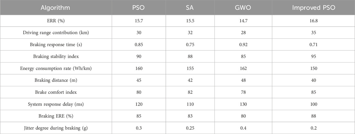
Table 2. RBC performance of EVs with different algorithms under various working conditions.
In Table 2, from the perspective of ERR, the improved PSO performs the best, reaching 16.8%. In terms of driving range contribution, the PSO has been improved to 35 km. The improved PSO has the shortest braking response time, taking only 0.71 s. In terms of braking stability index, the improved PSO also has the highest score, at 95, PSO at 90, SA and GWO at 88 and 85. The energy consumption rate of improved PSO is the lowest, at 150 Wh/km, SA is 155 Wh/km, PSO and GWO are 160 Wh/km and 162 Wh/km. Improved PSO performs the best in ERR, braking response time, and braking stability, while having the lowest energy consumption rate, demonstrating superior performance in EVs RBC. Table 3 compares the RBC performance of EVs under various operating conditions. The working conditions are based on the framework of the World Light-Duty Vehicle Test Cycle (WLTP) standard test profile, and the parameters are corrected in combination with the actual usage scenarios of the experimental vehicle. The specific driving conditions and overview are as follows: The urban working conditions are designed in reference to the “low-speed segment” (speed ≤50 km/h) in the WLTP standard. After correction, the average speed is 32 km/h, the maximum speed does not exceed 50 km/h, the braking frequency is 1.2 times per minute, the duration of each braking is 1.5–2 s, and the total test driving distance is 10 km. This working condition simulates the congested urban sections in China (the morning and evening rush hour traffic conditions in Yuzhong District, Chongqing City), with the reference basis being the 2024 Central Urban Area Road Driving Characteristics Report released by the Chongqing Municipal Commission of Transport. The suburban working conditions are designed in accordance with the “medium speed range” (50–80 km/h) in the WLTP standard. After correction, the average speed is 58 km/h, the maximum speed is 80 km/h, the braking frequency is 0.6 times per minute, the duration of each braking is 2–2.5 s, and the total test driving distance is 15 km. This working condition simulates the scenario of a suburban expressway (the suburban ring road in Banan District, Chongqing City), with the reference basis being the WLTP test regulations and the speed limit regulations for suburban roads in Chongqing City. The high-speed operating condition is based on the “high-speed section” (vehicle speed ≥80 km/h) in the WLTP standard. After correction, the average speed is 85 km/h and the maximum speed is 110 km/h. This operating condition simulates a highway scenario (the Chongqing section of G85 Chengdu-Chongqing Expressway). For specific parameter calibration, please refer to the 2024 traffic flow data report of the Chongqing section of G85.
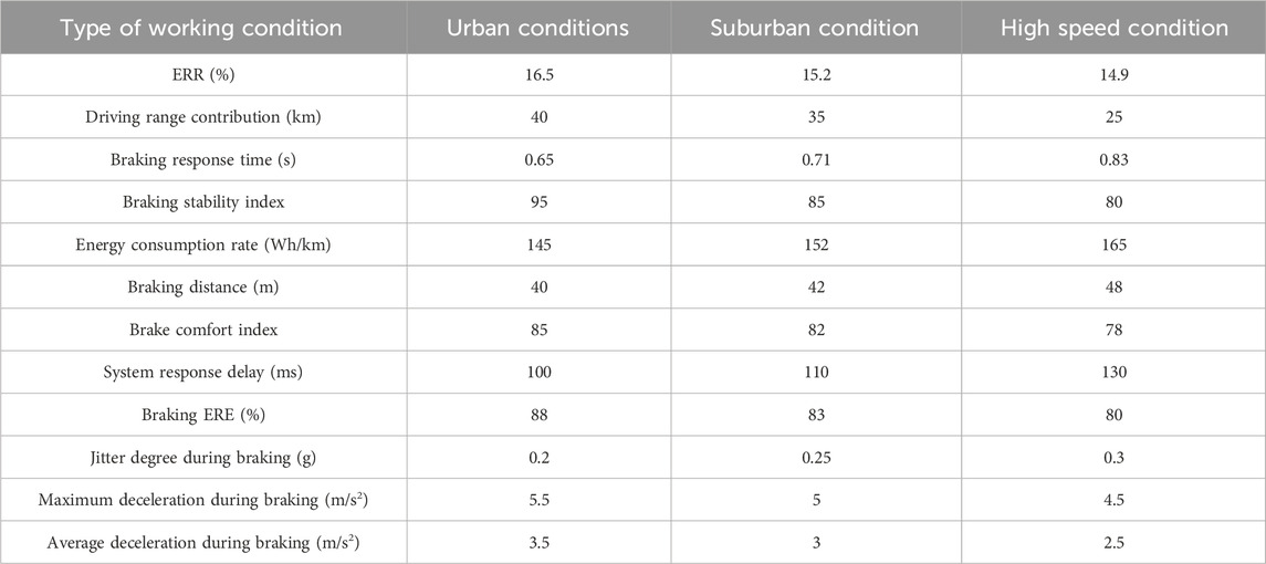
Table 3. Comparison of RBC performance of EVs under different working conditions.
In Table 3, under urban working conditions, the highest ERR is 16.5%, the contribution of driving range is 40 km, the braking response time is 0.65 s, the braking stability index is 95, and the energy consumption rate is 145 Wh/km. The values under suburban conditions are 15.2%, 35 km, 0.71 s, 85, and 152 Wh/km. The five values under high-speed conditions are 14.9%, 25 km, 0.83 s, 80, and 165 Wh/km. Under urban working conditions, EVs exhibit the best ERR and braking stability, but have the lowest energy consumption rate. Under suburban conditions, although the ERR is slightly lower, the contribution of driving range is relatively high, and the braking response time and energy consumption rate are at a moderate level. Under high-speed conditions, although the contribution of driving range is the highest, the ERR and braking stability are poor, and the energy consumption rate is the highest. To further demonstrate the superiority of the research strategy, supplementary horizontal comparison data between standard operating conditions and conventional braking methods are provided, as shown in Table 4.
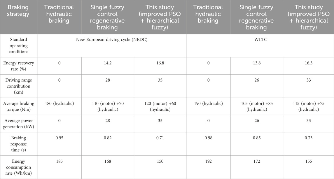
Table 4. Performance Comparison of different Braking Strategies under standard operating conditions.
As shown in Table 4, under the two standard operating conditions of NEDC and WLTC, the improved PSO + hierarchical fuzzy braking strategy proposed in the research has an energy recovery rate that is 2.6% and 2.5% higher respectively compared to the single fuzzy control regenerative braking, an increase of 7–8 km in driving range contribution, and an increase of 6–7 kW in average power generation. The braking response time is shortened by 0.1–0.12 s, and the energy consumption rate is reduced by 18 to 17 Wh/km, which is significantly superior to traditional hydraulic braking (without energy recovery).
4 Conclusion
This study aims to address the challenges faced by EVs in ERE and range, by optimizing RBC strategy to optimize the EUE and braking performance of EVs. To this end, this study developed an EV-RBC strategy scheme based on HFC technology and adjusted through an optimized PSO algorithm. In the experiment, the improved strategy significantly increased the ERR of EVs to 16.8% in energy recovery, which was about 1.1% higher than traditional methods. In terms of driving range, the contribution of driving range has increased to 35 km, indicating that this strategy has significant advantages in improving EUE. In terms of braking performance, the braking response time has been shortened to 0.71 s, and the braking stability index has reached 95, demonstrating the superiority of this control strategy in ensuring vehicle braking safety and stability. In addition, the energy consumption rate was reduced to 150 Wh/km, further verifying the effectiveness of this strategy in energy conservation. The fuzzy control system based on improved PSO exhibited significant performance improvement during the optimization process. However, under high-speed operating conditions, the ERR and braking stability still need to be further improved, and the adaptability of this control strategy under different operating conditions still needs to be optimized. Future research will further optimize control strategies to improve their adaptability and robustness under different operating conditions.
Data availability statement
The original contributions presented in the study are included in the article/supplementary material, further inquiries can be directed to the corresponding author.
Author contributions
JZ: Writing – original draft, Methodology, Conceptualization. QC: Investigation, Writing – original draft, Data curation. JZ: Supervision, Writing – review and editing, Formal Analysis. GL: Writing – review and editing, Resources, Project administration.
Funding
The authors declare that financial support was received for the research and/or publication of this article. The research is supported by 2023 Chongqing Higher Education Association Project: “Research and Practice on the Training Model of Innovative Talents under the Deep Integration Platform of Industry, Science and Education”, Project Number: cqgj23136C; 2024 Ministry of Education supply-demand docking employment and education project: “Exploration and Practice of Deep Integration of Industry, Science and Education to Cultivate Innovative Applied Talents”, project number: 2024010318756.
Conflict of interest
The authors declare that the research was conducted in the absence of any commercial or financial relationships that could be construed as a potential conflict of interest.
Generative AI statement
The authors declare that no Generative AI was used in the creation of this manuscript.
Any alternative text (alt text) provided alongside figures in this article has been generated by Frontiers with the support of artificial intelligence and reasonable efforts have been made to ensure accuracy, including review by the authors wherever possible. If you identify any issues, please contact us.
Publisher’s note
All claims expressed in this article are solely those of the authors and do not necessarily represent those of their affiliated organizations, or those of the publisher, the editors and the reviewers. Any product that may be evaluated in this article, or claim that may be made by its manufacturer, is not guaranteed or endorsed by the publisher.
Abbreviations
PSO, Particle Swarm Optimization/; HFC, Hierarchical Fuzzy Control/; EVs, Electric Vehicles/; EUE, Energy Utilization Efficiency %; BER, Braking Energy Recovery/; RBS, Regenerative Braking System/; RBC, Regenerative Braking Control/; ERE, Energy Recovery Efficiency %; ERR, Energy Recovery Rate %; FABF, Front Axle Braking Force N; RABF, Rear Axle Braking Force N; MBF, Mechanical Braking Force N; HBF, Hydraulic Braking Force N; PMSM, Permanent Magnet Synchronous Motor/; SOC, State of Charge/; NoI, Number of Iterations Times; SA, Simulated Annealing/; GWO, Grey Wolf Optimizer/; WLTP, World Light-Duty Vehicle Test Cycle/; NEDC, New European Driving Cycle/.
References
Abd-Elhaleem, S., Shoeib, W., and Sobaih, A. A. (2023). Improved power management under uncertain driving conditions for plug-in hybrid electric vehicles via intelligent controller. IEEE Trans. Intelligent Transp. Syst. 24 (12), 13698–13712. doi:10.1109/tits.2023.3308509
Anita, S., Sukhi, Y., Jeyashree, Y., and Manoj Kumar, N. (2024). Torque fault compensation in electric vehicle switched reluctance motor drives: a jellyfish search optimization method. Optim. Control Appl. Methods 45 (5), 1990–2007. doi:10.1002/oca.3133
Azim, M. N., Bayati, N., and Ebel, T. (2024). Energy management strategies of hybrid electric vehicles: a comparative review. IET Smart Grid 7 (3), 191–220. doi:10.1049/stg2.12133
Beşkardeş, A., Hameş, Y., and Kaya, K. (2024). A comprehensive review on fuzzy logic control systems for all, hybrid, and fuel cell electric vehicles. Soft Comput. 28 (13), 8183–8221. doi:10.1007/s00500-023-09454-5
Bingül, Ö., and Yıldız, A. (2023). Fuzzy logic and proportional integral derivative based multi-objective optimization of active suspension system of a 4×4 in-wheel motor driven electrical vehicle. J. Vib. Control 29 (5-6), 1366–1386. doi:10.1177/10775463211062691
Chai, W. S., bin Romli, M. I. F., Yaakob, S. B., Fang, L. H., and Aihsan, M. Z. (2022). Regenerative braking optimization using particle swarm algorithm for electric vehicle. J. Adv. Comput. Intell. Intelligent Inf. 26 (6), 1022–1030. doi:10.20965/jaciii.2022.p1022
Guo, N., Zhang, W., Li, J., Chen, Z., Li, J., and Sun, C. (2024). Predictive energy management of fuel cell plug-in hybrid electric vehicles: a co-state boundaries-oriented PMP optimization approach. Appl. Energy 362, 122882. doi:10.1016/j.apenergy.2024.122882
Guo, N., Liu, J., Li, J., Chen, W., Zhang, Y., Lu, Q., et al. (2025). Handling-stability control for distributed drive electric vehicles via Lyapunov-based nonlinear MPC algorithm. IEEE Trans. Transp. Electrification 11 (2), 6615–6628. doi:10.1109/tte.2024.3513438
Hasanvand, M., Nooshyar, M., Moharamkhani, E., and Selyari, A. (2023). Machine learning methodology for identifying vehicles using image processing. Artif. Intell. Appl. 1 (3), 154–162. doi:10.47852/bonviewaia3202833
Heydari, S., Fajri, P., Lotfi, N., and Rasheduzzaman, M. (2023). Maximum-current curve operation of electric vehicles for improved energy recuperation during regenerative braking. SAE Int. J. Electrified Veh. 12 (2), 145–155. doi:10.4271/14-12-02-0007
Luo, D., Yang, W., Wang, Y., Han, Y., Liu, Q., and Yang, Y. (2024). Investigation of regenerative braking for the electric mining truck based on fuzzy control. Int. J. Veh. Perform. 10 (1), 73–95. doi:10.1504/ijvp.2024.135452
Mohammad, K. S., and Jaber, A. S. (2022). Comparison of electric motors used in electric vehicle propulsion system. Indonesian J. Electr. Eng. Comput. Sci. 27 (1), 11–19. doi:10.11591/ijeecs.v27.i1.pp11-19
Nandakumar, M. (2024). Design of BLDC motor drive system using alternative controllers for performance evaluation in electric vehicle applications. Int. J. Veh. Des. 94 (1-2), 57–82. doi:10.1504/ijvd.2024.136234
Ponce, P., MacCleery, B., Soriano, L. A., García, M., Leví, V., and Molina, A. (2022). Expanding electric vehicles lifetime in power electronic stage using an optimized fuzzy logic controller. Int. J. Interact. Des. Manuf. (IJIDeM) 16 (1), 49–63. doi:10.1007/s12008-021-00794-w
Pukkunnen, E. B., Joseph, N. M., Jos, B. M., Joy, M. C., and Eldhose, K. A. (2023). Performance investigation and energy optimisation in hybrid electric vehicle model using reinforcement learning and fuzzy controller. Int. J. Veh. Perform. 9 (1), 73–90. doi:10.1504/ijvp.2023.128039
Ratchanyaraj, I. A. J., and Ravindran, R. S. (2024). Developed an improved fractional ordered darwinian particle swarm optimization using fuzzy logic controller to improve the performance measures on E-Vehicle. Electr. Power Components Syst. 52 (6), 929–945. doi:10.1080/15325008.2023.2237025
Ren, G., Zhang, G., Shi, W., Si, Y., and Duan, Y. (2023). Regenerative braking control strategy optimisation based on hybrid power source and PSO. Int. J. Mechatronics Manuf. Syst. 16 (1), 37–54. doi:10.1504/ijmms.2023.132010
Saiteja, P., Ashok, B., Wagh, A. S., and Farrag, M. E. (2022). Critical review on optimal regenerative braking control system architecture, calibration parameters and development challenges for EVs. Int. J. Energy Res. 46 (14), 20146–20179. doi:10.1002/er.8306
Shu, H. (2025). Hybrid energy storage system for intelligent electric vehicles incorporating improved PSO algorithm. Energy Inf. 8 (1), 30–16. doi:10.1186/s42162-025-00488-7
Suyambu, M. R., and Vishwakarma, P. K. (2023). Improving efficiency of electric vehicles: an energy management approach utilizing fuzzy logic. Int. J. Adv. Res. Sci. Commun. Technol. 3 (2), 737–748. doi:10.48175/ijarsct-9749v
Valladolid, J. D., and Macas, J. (2023). “A proposed strategy for the optimal control of regenerative braking in electric vehicle based on driving style,” in IEEE vehicle power and propulsion conference (VPPC). IEEE, 1–5.
Zhang, Y., Wang, W., Xiang, C., Yang, C., Peng, H., and Wei, C. (2022). A swarm intelligence-based predictive regenerative braking control strategy for hybrid electric vehicle. Veh. Syst. Dyn. 60 (3), 973–997. doi:10.1080/00423114.2020.1845387
Keywords: electric vehicles, regenerative braking, fuzzy control, particle swarm optimization, energy recovery
Citation: Zuo J, Chai Q, Zuo J and Li G (2025) Control strategy of electric vehicle regenerative braking integrating fuzzy control and PSO. Front. Mech. Eng. 11:1697447. doi: 10.3389/fmech.2025.1697447
Received: 02 September 2025; Accepted: 10 November 2025;
Published: 28 November 2025.
Edited by:
Muhammad Aziz, The University of Tokyo, JapanReviewed by:
Ningyuan Guo, Foshan University School of Mechatronic Engineering and Automation, ChinaGianluca Del Papa, National Research Council (CNR), Italy
Copyright © 2025 Zuo, Chai, Zuo and Li. This is an open-access article distributed under the terms of the Creative Commons Attribution License (CC BY). The use, distribution or reproduction in other forums is permitted, provided the original author(s) and the copyright owner(s) are credited and that the original publication in this journal is cited, in accordance with accepted academic practice. No use, distribution or reproduction is permitted which does not comply with these terms.
*Correspondence: Jianping Zuo, enVvanAyMDAzQDE2My5jb20=