 Amnart Boonloi1
 Withada Jedsadaratanachai2*
- 1Department of Mechanical Engineering Technology, College of Industrial Technology, King Mongkut’s University of Technology North Bangkok, Bangkok, Thailand
- 2Department of Mechanical Engineering, School of Engineering, King Mongkut’s Institute of Technology Ladkrabang, Bangkok, Thailand
This study numerically investigates the enhancement of heat exchanger performance using a passive technique based on vortex generation. The proposed enhancement device, termed a diamond-shaped orifice (DSO), is a modified configuration that combines a conventional orifice plate with a conical ring. The DSO is inserted into a circular tube to modify the flow structure and induce strong vortices, thereby promoting convective heat transfer and improving the overall thermal performance. The effects of key geometric parameters, including the attack angle (α = 20°, 30°, and 45°), flow blockage ratio (FBR = 0.05–0.30), and pitch ratio (PRT = 1–2), are systematically examined under turbulent airflow conditions with Reynolds numbers ranging from 3,000 to 20,000. The results reveal that incorporating the DSO generates intense swirling flow, which effectively disrupts the thermal boundary layer and enhances the convective heat transfer coefficient. The maximum Nusselt number improvement reached 7.16 times that of a plain tube, while the highest thermal enhancement factor (TEF) attained was 1.77, indicating a substantial improvement in heat exchanger performance without additional active energy input.
1 Introduction
Heat is a vital form of energy that plays an essential role in driving various systems that support human life. Thermal energy serves as a primary driving force in numerous industrial processes and diverse engineering systems. Recognizing its importance, many organizations have begun to develop strategic plans and practical solutions to utilize thermal energy in the most efficient and cost-effective manner possible. The issue of maximizing thermal energy efficiency and effectiveness has become a prominent concern, not only at the national level but also in global discussions. Both governmental and private sectors have invested significant resources into research efforts aimed at promoting the efficient use of thermal energy. One of the key research areas contributing to this goal is the increment of the efficiency and performance of heat exchangers and thermal systems.
Enhancing the thermal performance of heat exchanger systems can be achieved through various approaches. One promising method that offers improved efficiency without significantly increasing energy consumption is known as the passive method. This approach involves modifying the flow structure and enhancing HT by integrating specially designed devices that generate vortex flow, a mechanism known to improve the convective HT. Numerous studies have explored the selection of vortex generators as a means to enhance HT. In particular, this research focuses on insert-type vortex generators, such as conical rings, twisted tapes, baffle/rib, winglet, which are embedded directly within the heat exchanger to promote swirling flow and thermal mixing. Rinik et al. (2025) numerically investigated HT enhancement using an elliptical twisted inner pipe combined with convergent conical ring turbulators under turbulent flow conditions (Re = 5,000–26000) in a double-pipe heat exchanger. They reported that the full twists generated a swirling motion, while the conical rings inserted inside the outer pipe acted as passive turbulators that guided the flow toward the inner pipe, where the hot fluid passed. Within the investigated range, the highest performance evaluation criterion (PEC) was found to be approximately 2.3. Similarly, Li et al. (2024) employed conical rings to enhance the thermal performance of a micro combustor. Kumar et al. (2023) experimentally investigated HT and friction losses in a heat exchanger using perforated conical rings, twisted tapes, and CuO/H2O nanofluids. The highest thermal-hydraulic performance within their investigated range was approximately 1.45. Hassan et al. (2022) used solid and perforated conical rings to augment HT and improve performance under turbulent flow conditions, concluding that the optimal thermal enhancement factor was 1.2. Alqaed et al. (2024) presented a study on turbulent flow (water–copper nanofluid) in a power plant heat exchanger equipped with conical ring-vortex turbulators. They showed that the smallest turbulator length and diameter, combined with an inter-turbulator distance of 145 mm, generated the maximum frictional entropy. In contrast, smaller distances between turbulators with larger turbulator dimensions resulted in the lowest friction loss. They also summarized that the increasing the hole diameter significantly reduced thermal (by 98.7%), frictional (by 72.5%), and total entropy generation (by 98.5%). Ibrahim et al. (2019) conducted a computational study on HT analysis in a circular tube equipped with conical ring turbulators. They reported that the highest enhancement in tube efficiency was 1.291, and entropy generation increased with increasing Reynolds number for all conical ring configurations. Kumar et al. (2020) proposed new empirical correlations for both HT and pressure drop caused by internal conical ring-vortex generators in an impinging jet solar air heater passage. The optimum HT was found at a relative inside conical ring height of 0.110, a ratio of inlet flow diameter to the inner print diameter of the ring of 1.7, a ratio of ring diameter to ring height of 2.33, a relative X-axis pitch of 5.28, and a relative Y-axis pitch of 3.42. Nakhchi and Esfahani (2019a) and Nakhchi and Esfahani (2019b) numerically investigated turbulent Cu–water nanofluid flow and studied the effects of different geometrical parameters of perforated conical rings on flow structure and HT in heat exchangers. They observed that the HT enhancement provided by the perforated conical rings was 278.2% greater than that of a smooth tube, with the best thermal performance of 1.10 at Re = 5,000. However, rising the number of holes from 4 to 10 reduced the Nusselt number by up to 35.48%, with a maximum thermal performance factor of 1.241. Anvari et al. (2014) and Anvari et al. (2011) experimentally and numerically investigated thermal behavior in tubes with special conical ring-vortex generators. Their results indicated that when water was used as the working fluid (as opposed to air), the conical ring inserts had an unfavorable effect on HT enhancement efficiency. Additionally, the insertion of turbulators enhanced the Nusselt number by up to 521% for diverging conical ring arrangements and up to 355% for converging arrangements, although turbulators caused a significant increase in pressure drop. Sheikholeslami et al. (2016) presented experimental and numerical analyses on the effects of conical rings on turbulent flow and HT in a double-pipe air-to-water heat exchanger. They reported that friction factor decreased with increasing open area ratio, pitch ratio, and Reynolds number, while the Nusselt number decreased with increasing open area ratio and pitch ratio but increased with Reynolds number. They further concluded that thermal performance improves with increasing conical angle for a direct conical ring array. Mohammed et al. (2019) studied two-phase forced convection of nanofluid flow in circular tubes using convergent and divergent conical ring inserts. They claimed that the best performance enhancement criterion, based on the similar pumping force, was achieved by divergent ring arrangement with an improvement of 365%. They also noted that the two-phase mixture model gives more accurate than the single-phase model when compared with experimental and numerical results. Sripattanapipat et al. (2016) numerically investigated HT in a heat exchanger tube with hexagonal conical-ring inserts. Their results showed that V-shaped hexagonal conical rings led to significantly greater HT than the reference case or a smooth tube, while also providing a lower friction factor. Finally, Kongkaitpaiboon et al. (2010a) experimentally investigated HT and turbulent flow friction in tubes fitted with perforated conical rings. The highest thermal performance factor of approximately 0.92 was found at a pitch ratio of 4 and Reynolds number of 4,000. In addition to conical rings, other types of vortex generators—such as twisted tapes (Bizuneh et al., 2025; Kumar and Afzal, 2025; V P et al., 2025; Abajja et al., 2025; Bhattacharyya et al., 2025), baffles/ribs (Salhi et al., 2025; Wang et al., 2025; Zhan et al., 2025; Li et al., 2025; Bennour et al., 2025), and winglets (Feng et al., 2024; Suchatawat et al., 2025; İĞCİ, 2025; Tian et al., 2024; Majmader and Hasan, 2024)—are also commonly employed to rise convective HT and heat exchanger performance.
In this study, the geometric concepts of conical rings and orifices are combined and developed into a novel vortex generator, referred to as the Diamond-Shaped Orifice (DSO), for rising HT in circular tube heat exchangers (CT-HX). The DSO offers several advantages, including ease of fabrication and structural stability when installed in CT-HX. The edges and corners of the DSO play a crucial role in securing the structure firmly within the tube, ensuring reliable performance under actual operating conditions. The gap between the DSO and the inner wall of the tube helps to induce vortex flow, which promotes thermal mixing and enhances HT. Additionally, the DSO design contributes to reducing the pressure drop or friction loss in the system—an important factor in minimizing the required pumping power. A computational fluid dynamics (CFD) approach with a commercial code is adopted to investigate the performance of the proposed DSO. This numerical method allows for detailed analysis and understanding of the flow and thermal behavior within the heat exchanger, which is essential for further optimizing the DSO geometry and advancing heat exchanger design in future applications.
2 Numerical model of the CT-HX inserted with DSO, boundary and initial conditions
The heat exchanger tube used in this study is a circular tube heat exchanger (CT-HX) with an inner diameter of 0.05 m. The DSO units are installed within the CT-HX as illustrated in Figure 1a. The thickness (in y-x plane) of each DSO plate is denoted by e, and the ratio of thickness to tube diameter (e/D) is referred to as the flow blockage ratio (FBR), which takes values of 0.05, 0.10, 0.15, 0.20, 0.25, and 0.30. The axial spacing between adjacent DSO plates (pitch distance) is denoted by P, and the ratio of spacing to tube diameter (P/D) is defined as the pitch ratio (PRT), with values of 1, 1.5, and 2. The attack angle of the DSO plate, represented by α, is set at 20°, 30°, and 45°. The study is conducted under turbulent air flow, with Reynolds numbers varying from 3,000 to 20,000, determined based on the flow conditions at the CT-HX inlet. The computational domain is modeled using a periodic module with a length denoted by L, and the ratio L/D is equal to 1, 1.5, and 2 for the cases of PRT = 1, 1.5, and 2, respectively. The case studies of the present research are summarized in Table 1. The ranges of the parameters are additionally presented.
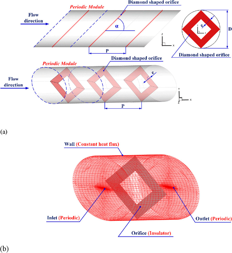
Figure 1. Numerical model description for (a) Model configuration and (b) boundary condition.
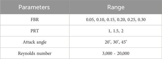
Table 1. Case studies.
The computational model of the CT-HX with DSO inserts is defined with boundary conditions as illustrated in Figure 1b. Periodic boundary conditions are applied at both the inlet and outlet planes for both the flow and thermal fields. The CT-HX wall is subjected to a constant heat flux condition of 600 W/m2, while the DSO plates are modeled as adiabatic surfaces with a heat flux of 0 W/m2.
The initial conditions and assumptions used in this study are summarized as follows:
• The working fluid is air with an initial temperature of 300 K. The flow and HT at the CT-HX inlet are assumed to be fully developed.
• The variation in air temperature during the simulation is within 20 °C/K, allowing the thermophysical properties to be treated as constant.
• The flow and HT are assumed to be three-dimensional and steady-state.
• Only forced convection is measured in the HT analysis. Natural convection and thermal radiation are negligible and thus not taken into account.
• Body forces and viscous dissipation are also neglected.
3 Mathematical foundation
Based on the details of the investigation stated above, the governing equations used in the current study are as follows (Cengel and Ghajar, 2015):
The continuity equation employed in this research is presented in Equation 1. The flow and HT phenomena are governed by the momentum and energy equations, which are formulated in Equations 2, 3, respectively.
Γ and Γt denote the molecular and turbulent thermal diffusivities, respectively, and are calculated as Equation 4:
The Reynolds-averaged approach to turbulence modeling requires that the Reynolds,
Here, the turbulent kinetic energy, k, is defined by
Here,
The governing equations were discretized using the QUICK scheme and solved using the finite volume method, with pressure–velocity coupling achieved through the SIMPLE algorithm. A commercial CFD code was employed for the computations. Convergence was assumed when the normalized residuals for all variables fell below 10–5, and below 10–9 for the energy equation. The Reynolds number, friction factor, local Nusselt number, average Nusselt number, and thermal performance enhancement factor were calculated using Equations 9–13, respectively.
Here, Nu0 and f0 represent the Nusselt number and friction factor, respectively, for the smooth CT-HX.
4 Numerical validation of the numerical model
One of the most critical processes in numerical modeling is the validation of the computational model. In this study, the model validation under turbulent flow conditions is conducted in three parts: (1) validation using a smooth CT-HX; (2) a grid independence test to determine the appropriate mesh resolution; and (3) a comparison of the numerical results with available experimental data.
4.1 Smooth CT-HX validation
The predicted Nusselt number and friction factor for a smooth CT-HX obtained from the developed numerical model were compared with those calculated using a standard empirical correlation (Cengel and Ghajar, 2015) within the studied turbulent flow regime. The comparison results show that the discrepancies between the numerical and empirical values are 1.7% for the Nusselt number and 4.2% for the friction factor, respectively (see Figure 2). These small deviations indicate good agreement and validate the accuracy of the numerical model.
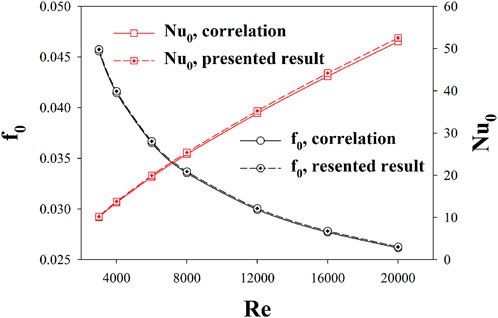
Figure 2. Smooth tube validation.
4.2 Grid independence
A grid independence study was conducted for the CT-HX equipped with a DSO (PRT = 1, FBR = 0.20, α = 30°) using five different grid densities: 80,000; 120,000; 220,000; 320,000; and 420,000 elements (see Figure 3). The comparison of results across these models revealed that increasing the grid count from 220,000 to 420,000 had negligible impact on both the Nusselt number and friction factor over the entire range of Reynolds numbers studied. Based on the balance between accuracy and computational cost, a grid resolution of approximately 220,000 elements was selected for all subsequent simulations. For models with extended domain lengths, the number of grid elements was scaled proportionally to maintain mesh quality and solution consistency.
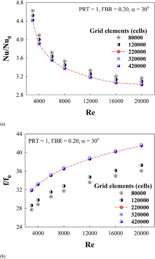
Figure 3. Grid independence for (a) Nu/Nu0 and (b) f/f0.
4.3 Comparison of the experimental result
Since there are no previous studies that have developed a vortex generator identical to the DSO proposed in this research, a validation was conducted by comparing the present model with reference studies (Kongkaitpaiboon et al., 2010b; Jedsadaratanachai and Boonloi, 2017), which investigated the use of a circular ring (Kongkaitpaiboon et al., 2010b) and a V-orifice (Jedsadaratanachai and Boonloi, 2017) installed inside a CT-HX. The comparison involved both the Nusselt number and the friction factor. The results revealed that the Nusselt number and friction factor obtained from the present model deviated from those reported in (Kongkaitpaiboon et al., 2010b) by approximately 6% and 15%, respectively. In contrast, the deviations from the data in (Jedsadaratanachai and Boonloi, 2017) were minimal, with differences of only 0.02% for both the Nusselt number and the friction factor. These findings indicate that the generated model is sufficiently reliable for predicting fluid flow behavior and HT in the CT-HX equipped with the proposed DSO vortex generator.
5 Numerical result and discussion
The numerical results obtained in this study are presented in two main parts. The first part focuses on the flow structure and HT characteristics within the CT-HX when DSO inserts are employed. Understanding these flow and thermal behaviors is essential for the further development of heat exchanger equipment and the design of vortex generators. The second part involves the analysis of the HT rate, pressure drop, and thermal performance, expressed in terms of dimensionless parameters.
5.1 Air flow topology and thermal structure in the CT-HX equipped with the DSO
Figure 4a illustrates the flow structure in the form of streamlines in a cross-sectional plane of the CT-HX equipped with DSO inserts at various attack angles, with Re = 8,000, PRT = 1 and FBR = 0.20. The results clearly show that the presence of the DSO significantly alters the flow structure compared to the smooth, plain tube, leading to the formation of vortical flows at all investigated attack angles. The vortex cores, denoted as VC, are highlighted in the figure. The flow exhibits top-bottom symmetry, which corresponds to the geometric symmetry of the DSO configuration. At an attack angle of 20°, the largest number of vortex cores is observed—typically ranging from 6 to 8 depending on the axial position along the tube. At 30°, fewer vortex cores are observed compared to the 20° case, but still more than at 60°, with six distinct vortex cores identified. At 60°, the number of vortex cores ranges between 4 and 6. The presence of a higher number of VCs is beneficial for enhancing the temperature distribution within the fluid, which positively affects the HT rate. However, it is also observed that as the number of vortex cores increases, the vortex strength of each core tends to decrease. This reduction in vortex strength may potentially lead to a decline in the overall HT performance. Therefore, it is not sufficient to draw conclusions based solely on the flow structure, and further analysis of the HT behavior is required.
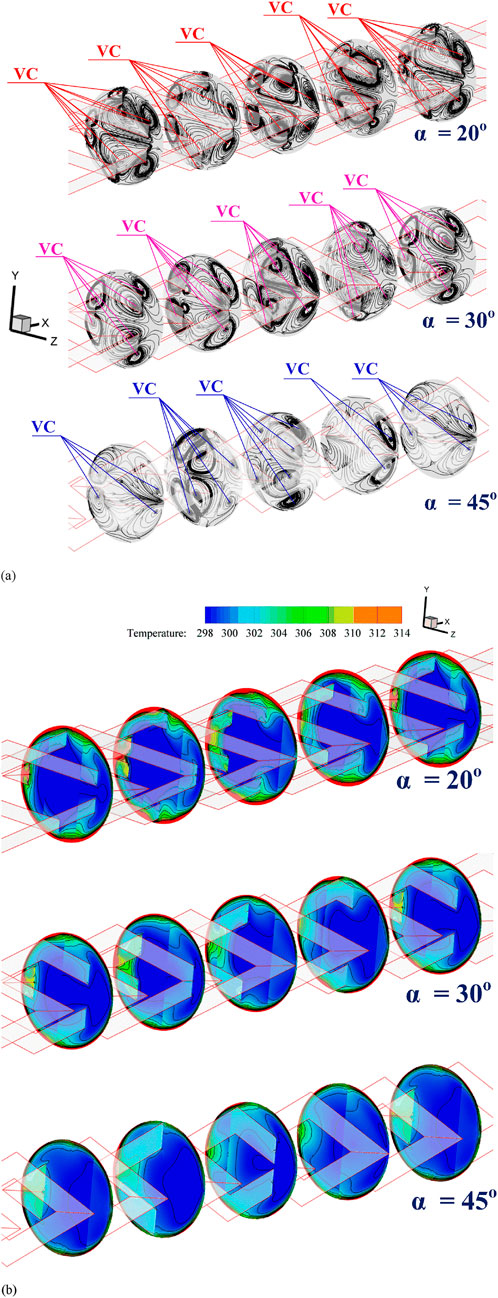
Figure 4. Mechanisms in the CT-HX inserted with the DSO for (a) streamlines in transverse planes and (b) temperature distribution in transverse planes at Re = 8,000, PRT = 1 and FBR = 0.20.
Figure 4b presents the thermal behavior in terms of temperature distribution across the transverse plane of the CT-HX equipped with DSO inserts, at Re = 8,000, PRT = 1, and FBR = 0.20, for various attack angles. It is clearly observed that the presence of DSO promotes vortex formation, which enhances the mixing and thermal distribution of the fluid at all investigated attack angles compared to the smooth, plain tube. In the contour plots, the blue regions represent low-temperature air, which is seen to spread outward from the center of the plane. Meanwhile, the red contours, indicating high-temperature air near the outer edge of the cross-sectional plane, become thinner due to enhanced thermal mixing. Among the investigated cases, the attack angle of 45° exhibits the thinnest high-temperature layer near the wall, whereas the 20° case shows the opposite trend. This indicates that the 45° attack angle generates the strongest vortex structures compared to the other configurations. The red temperature contours can also be used to indicate the disturbance of the T-BL. The results suggest that an attack angle of 45° leads to the most significant T-BL disturbance among the tested cases. For the case with a 30° attack angle, the disturbance is greater than that observed at 20°, indicating a progressive increase in T-BL disruption with increasing attack angle.
When considering the variations in flow structure resulting from different flow blockage ratios (FBR), as illustrated in Figure 5, it is observed that vortex generation occurs at all FBR values. The number of vortex cores (VC) for each attack angle remains relatively similar across different FBRs (see Figure 6). However, the positions of the vortex cores may exhibit slight shifts depending on the FBR.
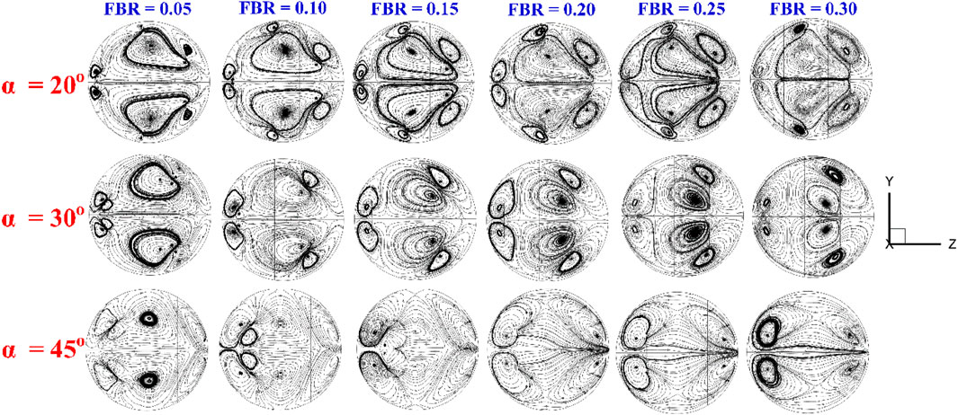
Figure 5. Streamlines in transverse planes in CT-HX inserted with the DSO at various flow attack angles and FBR for PRT = 1.
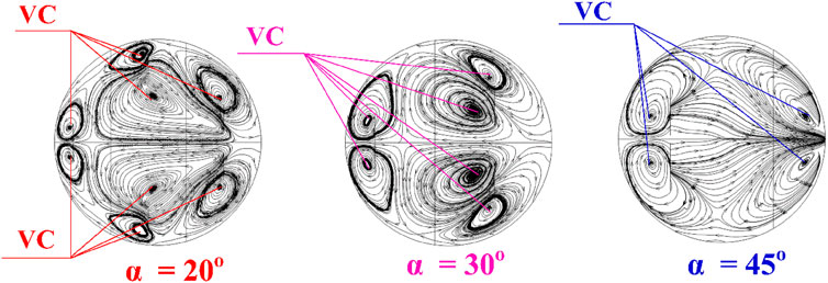
Figure 6. Vortex core description at various flow attack angles.
The mechanism of vortex generation in the CT-HX equipped with DSO inserts can be explained as follows. The DSO acts as a flow obstruction, creating a pressure difference between its front and rear surfaces. This pressure gradient induces vortex formation as air flows past the DSO. Figure 7 shows the longitudinal flow streamlines in the CT-HX with DSO inserts at various FBR values. It is clearly observed that as the FBR increases, the length of the longitudinal helical vortices becomes shorter. A higher FBR leads to a greater pressure differential across the DSO, resulting in stronger vortex generation. Consequently, at FBR = 0.30, the highest vortex strength is observed, while at FBR = 0.05, the vortex strength is the weakest.
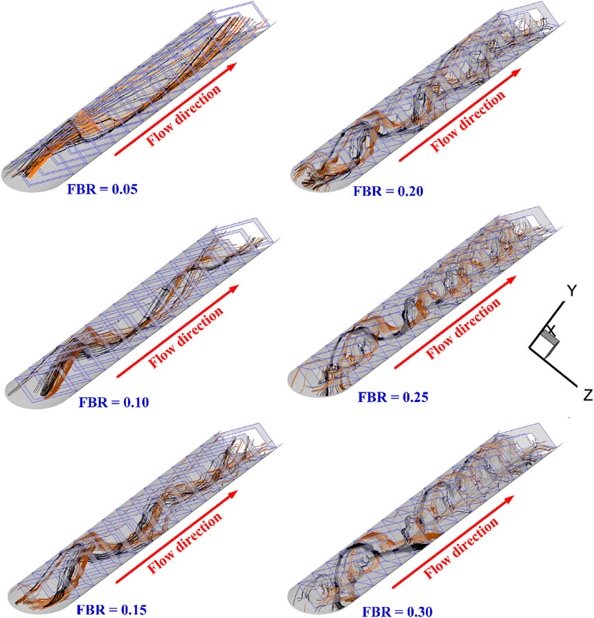
Figure 7. Longitudinal flow in the CT-HX inserted with the DSO at various FBR for PRT = 1, α = 30° and Re = 8,000.
Upon examining the vortex structures generated within the CT-HX equipped with DSO inserts, it is found that the vortices can be categorized into two distinct regions. The first region consists of vortices that do not interact with the CT-HX wall (as shown in Figure 8a). These vortices enhance fluid mixing by promoting better interaction between fluid layers of different temperatures, thereby improving thermal homogeneity. The second region involves vortices that impinge upon the CT-HX wall (see Figure 8b). These vortices directly disturb the T-BL, leading to what is referred to as T-BL disturbance. As a result, the T-BL becomes thinner, which increases the local convective HT coefficient at the wall. Both of these mechanisms—enhanced fluid mixing and T-BL disturbance—play a crucial role in augmenting the HT rate within the CT-HX.
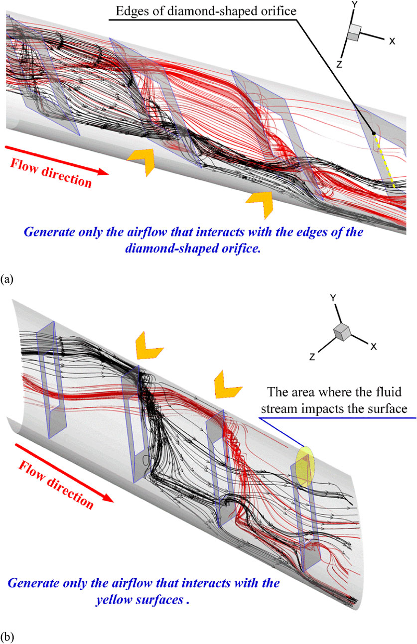
Figure 8. Longitudinal flow in the CT-HX inserted with the DSO for (a) vortex flow passes edges of the DSO and (b) impinging flow on the CT-HX wall at the leading edge of the DSO.
Figure 9 illustrates the temperature distribution of air in the cross-sectional plane for different values of FBR and flow attack angles. It is clearly observed from the figure that the air temperature distribution improves in all investigated cases. The blue temperature contours are dispersed outward from the center of the plane, while the red contours near the plane boundaries become thinner (see Figure 10). Upon examining the red contours, it is found that an increase in FBR results in a thinner red contour region. This phenomenon is attributed to the enhancement of vortex strength associated with higher FBR values. The increase in vortex strength intensifies the disturbance of the T-BL. Consequently, the reduced thickness of the red contour indicates a greater level of T-BL disturbance.
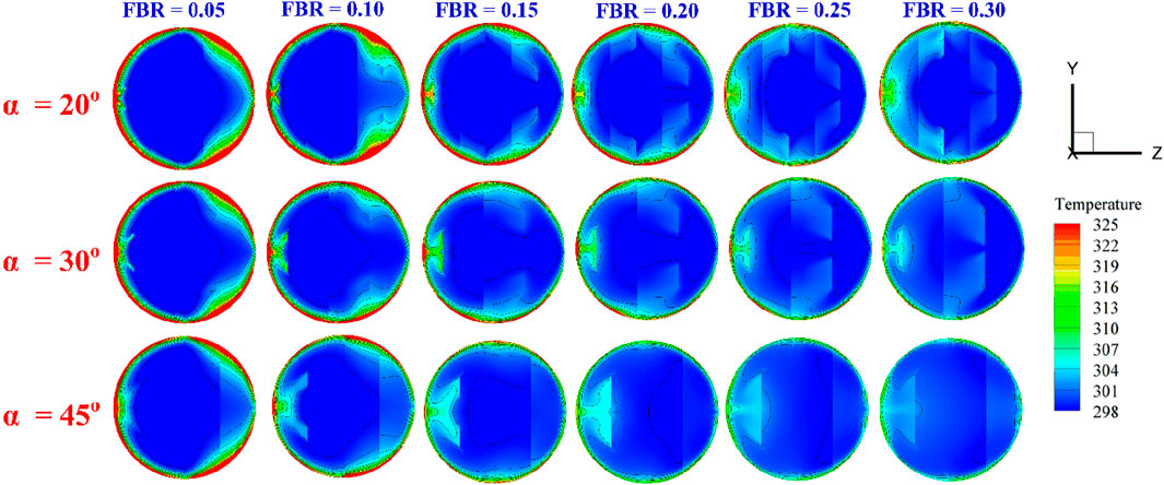
Figure 9. Temperature distributions in transverse planes in the CT-HX inserted with the DSO at various flow attack angles and FBR for PRT = 1.
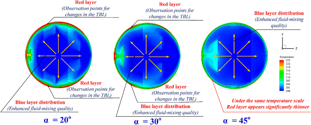
Figure 10. Thermal behavior description in the CT-HX inserted with the DSO at various flow attack angles.
Figures 11a–c present the Nusselt number distribution contours on the CT-HX surface for flow attack angles (α) of 20°, 30°, and 45°, respectively, at various PRT and FBR values. It can be observed that the presence of DSO enhances the Nusselt number compared to the smooth plain tube in all investigated cases. This enhancement is primarily due to the generation of swirling flow that impinges on the CT-HX surface, leading to an increase in convective HT coefficient and improved fluid mixing. Localized red contours are observed on the CT-HX surface, indicating regions with significantly higher Nusselt numbers. These areas correspond to the impingement zones of the vortex flow (see Figure 12 in conjunction with Figure 8b), where the convective HT is notably intensified. In all cases, the impingement occurs consistently at the leading edge of the DSO, which is identified as the primary region of elevated HT performance (refer to Figure 8b). An increase in FBR and a decrease in PRT lead to stronger vortex structures, which, in turn, further enhance the Nusselt number due to more intense T-BL disturbance.
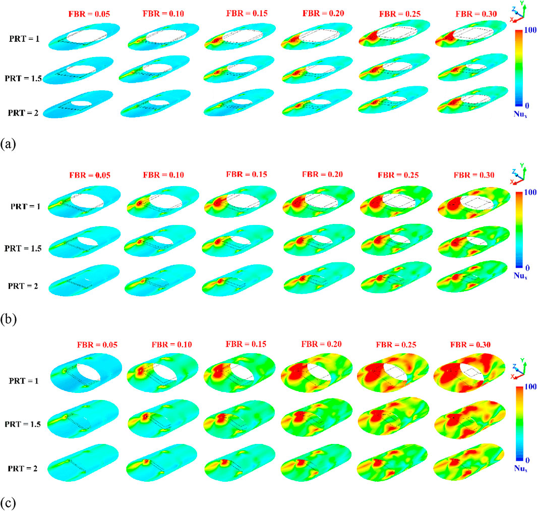
Figure 11. Nusselt number contours on the CT-HX surface of the CT-HX inserted with the DSO at various FBR and PRT for (a) α = 20°, (b) α = 30° and (c) α = 45° at Re = 8,000.
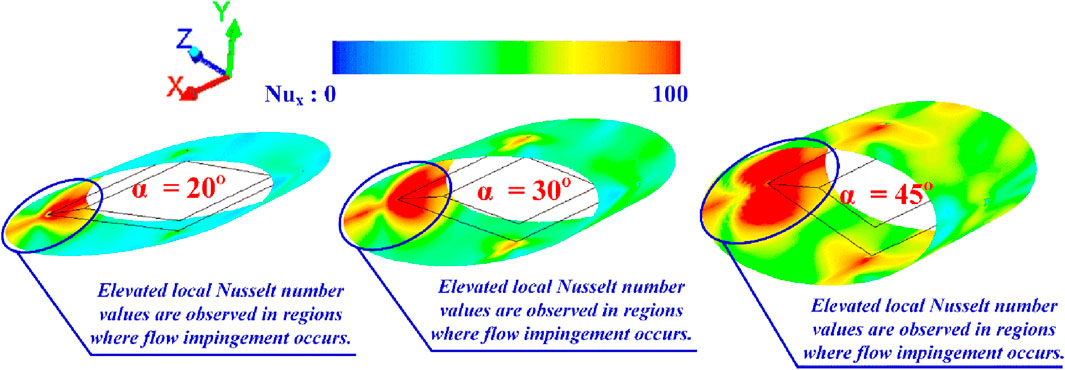
Figure 12. Description of contours Nusselt number at various flow attack angles.
Figure 13 summarizes the flow behavior and HT mechanisms in the CT-HX equipped with a DSO (Diamond-Shaped Orifice). When the DSO is installed, it acts as a flow obstruction, creating a pressure difference between its upstream and downstream sides. This pressure gradient induces vortex formation. A portion of the generated vortices impinges on the CT-HX wall, disturbing the T-BL. This interaction enhances the local convective HT coefficient and results in an increase in the local Nusselt number, as evidenced by the red contours in the Nusselt number distribution. Meanwhile, another portion of the vortices that does not directly impinge on the CT-HX wall contributes to improved mixing of fluid elements with different temperatures. This enhanced mixing further supports HT throughout the domain. Overall, these mechanisms—vortex-induced boundary layer disruption and thermal mixing—explain the significant improvement in overall HT rate and thermal performance when a DSO is incorporated into the CT-HX.
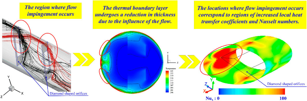
Figure 13. Conclusion of thermal and flow mechanisms in the CT-HX inserted with the DSO.
5.2 Enhanced heat transfer and pressure drop in the CT-HX equipped with the DSO
This section presents the evaluation of thermal performance in terms of dimensionless parameters. The HT rate is expressed using the Nusselt number, while the pressure drop is represented by the friction factor. The overall efficiency of the CT-HX is assessed using the thermal enhancement factor (TEF).
Figures 14a,b illustrate the variation of Nu/Nu0 vs. Re and f/f0 vs. Re, respectively, for a CT-HX equipped with DSO at different flow impingement angles, FBR values, and PRT values. It is evident that the presence of DSO leads to an increase in both the HT rate and the friction factor compared to the smooth plain tube, as indicated by Nu/Nu0 and f/f0 values greater than 1 in all examined cases. The enhancement in these parameters is attributed to the flow and HT mechanisms discussed previously. An increase in FBR and a decrease in PRT result in higher values of both Nu/Nu0 and f/f0, due to stronger vortex generation and more pronounced flow disturbance. The Nu/Nu0 ratio tends to decrease as Reynolds number increases, whereas the f/f0 ratio shows an increasing trend with higher Re values. Among the three tested impingement angles, α = 45° provides the highest HT and pressure drop, while α = 20° yields the lowest performance. Specifically, Nu/Nu0 ranges from 1.29 to 4.45, 1.83–5.60, and 1.77–7.16 for α = 20°, 30°, and 45°, respectively. Correspondingly, f/f0 values range from 2.80 to 27.69, 9.76–82.56, and 11.59–194.00 for α = 20°, 30°, and 45°, respectively.
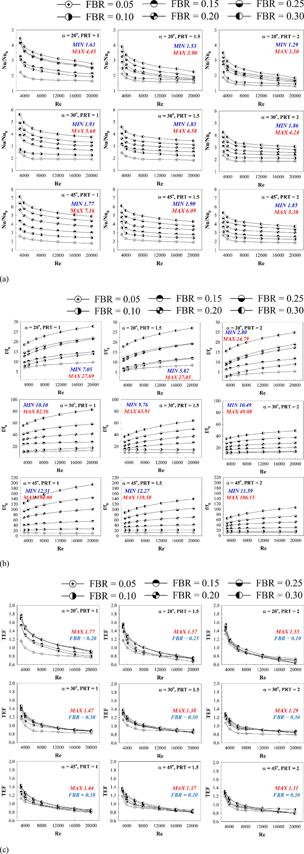
Figure 14. Performance assessments in the CT-HX inserted with the DSO for (a) Nu/Nu0 vs. Re, (b) f/f0 vs. Re and (c) TEF vs. Re.
5.3 TEF assessment in the CT-HX equipped with the DSO
Figure 14c presents the relationship between the Thermal Enhancement Factor (TEF) and the Reynolds number for various case studies. The results indicate that the installation of a DSO in the CT-HX enhances both the HT rate and the pressure drop across the system. While the increased HT rate is beneficial for improving thermal performance, the associated rise in pressure drop has a detrimental effect, as it requires additional pumping power. Therefore, to evaluate the practical effectiveness of incorporating the DSO, it is essential to assess performance at equal pumping power conditions, which is represented by the TEF. According to the results, TEF values show a decreasing trend with increasing Reynolds number in all investigated cases. The highest TEF values were observed as 1.77, 1.47, and 1.44 for flow impingement angles of 20°, 30°, and 45°, respectively. Among the evaluated configurations, the optimal TEF was achieved at PRT = 1. In terms of FBR, the best performance was observed at FBR = 0.20 for α = 20°, and at FBR = 0.30 for α = 30° and 45°.
Figure 15 presents a TEF contour plot constructed at Re = 3,000, showing the relationship between TEF, PRT, and FBR. Based on the figure, it can be concluded that for a flow impingement angle of 20°, the optimal FBR range yielding the highest TEF lies between 0.20 and 0.25. For flow impingement angles of 30° and 45°, the optimal FBR range shifts to 0.25–0.30. In all cases, the recommended PRT values fall within the range of 1–1.5. This contour plot serves as a practical reference for the preliminary prediction of TEF, offering guidance on suitable design parameters when implementing DSO in real-world heat exchanger applications.
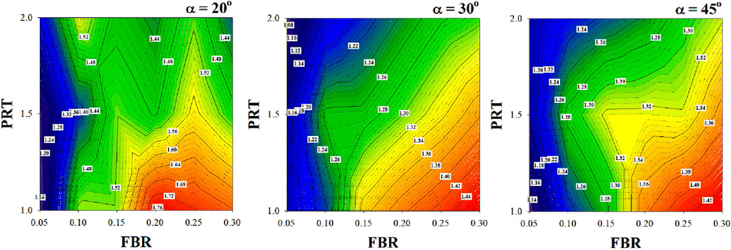
Figure 15. TEF contours at various PRT and FBR for Re = 3,000.
6 Conclusion
This study investigates the enhancement of HT and thermal performance in a CT-HX equipped with the DSO. The analysis focuses on the flow structure and thermal behavior under various configurations of the DSO: PRT = 1–2, FBR = 0.05–0.30, and flow impingement angles (α = 20°, 30°, and 45°). The investigation is conducted within the turbulent flow regime, with inlet Reynolds numbers ranging from 3,000 to 20,000. Based on the results, the following conclusions can be drawn:
• The installation of the DSO, which acts as a flow obstruction, induces a pressure difference between the upstream and downstream regions of the orifice. This pressure gradient generates vortex flow, which can be classified into two components. The first component does not impinge on the HT surface but enhances thermal mixing by promoting better interaction between air streams at different temperatures. The second component directly impinges on the CT-HX surface, disturbing the T-BL, which leads to an increase in the convective HT coefficient. This enhancement is directly correlated with an increase in the Nusselt number and, consequently, the overall HT rate.
• An increase in FBR and a decrease in PRT lead to an enhancement in both the HT rate and the friction factor. Among the tested configurations, a flow impingement angle of 45° results in the highest values of HT rate and pressure drop, while the angle of 20° yields the lowest performance in both aspects. Within the investigated Reynolds number range, the HT rate in the DSO-installed tube was found to be 1.29 to 7.16 times greater than that of the smooth plain tube. The maximum observed TEF was 1.77. The recommended design parameters based on the results are as follows: PRT: 1.0–1.5 for all cases, FBR: 0.20–0.25 for a flow angle of 20°, and 0.25–0.30 for flow angles of 30° and 45°.
• When comparing the TEF values of the present study with those reported in previous publications, it was found that the TEF in this study is higher than that of the conical ring-type vortex generator (Nakhchi and Esfahani, 2019b; Anvari et al., 2014; Sripattanapipat et al., 2016), due to its ability to generate greater vortex strength while maintaining a comparable or even lower system pressure drop in some cases. However, when compared to the V-orifice (Jedsadaratanachai and Boonloi, 2017), which conforms to the curvature of the tube along the orifice surface, the present study shows slightly lower TEF values in the cross-flow plane. Specifically, the V-orifice (Jedsadaratanachai and Boonloi, 2017) achieves a maximum TEF of 2.25, whereas the present study reaches a maximum of 1.77, indicating a reduction of approximately 21%. Nevertheless, in terms of installation stability, the current study exhibits a comparable stability trend while clearly producing a lower system pressure loss.
7 Additional recommendations
In considering the application of DSOs in industrial heat exchanger systems, it has been found that fabricating DSO plates is relatively straightforward and does not require strict selection of materials based on thermal conductivity. Furthermore, the installation of DSO plates is stable, as the four corners of each DSO provide support and prevent tilting in any direction. For future research, DSO plates could be adapted for use in other types of heat exchangers. Additionally, design modifications—such as converting the DSO into a V-shaped square-orifice configuration—could be explored to further enhance heat transfer rates while minimizing pressure drop in the system.
Data availability statement
The original contributions presented in the study are included in the article/supplementary material, further inquiries can be directed to the corresponding author.
Author contributions
AB: Resources, Writing – original draft, Investigation, Software, Funding acquisition, Visualization, Conceptualization, Formal Analysis, Validation, Data curation, Writing – review and editing, Methodology, Project administration, Supervision. WJ: Project administration, Resources, Validation, Visualization, Methodology, Conceptualization, Data curation, Formal Analysis, Investigation, Supervision, Funding acquisition, Writing – review and editing, Software, Writing – original draft.
Funding
The author(s) declare that financial support was received for the research and/or publication of this article. This research was funded by King Mongkut’s University of Technology North Bangkok, Contract no. KMUTNB-69-KNOW-07.
Acknowledgments
The authors would like to thank Prof. Pongjet Promvonge for suggestions.
Conflict of interest
The authors declare that the research was conducted in the absence of any commercial or financial relationships that could be construed as a potential conflict of interest.
Generative AI statement
The author(s) declare that no Generative AI was used in the creation of this manuscript.
Any alternative text (alt text) provided alongside figures in this article has been generated by Frontiers with the support of artificial intelligence and reasonable efforts have been made to ensure accuracy, including review by the authors wherever possible. If you identify any issues, please contact us.
Publisher’s note
All claims expressed in this article are solely those of the authors and do not necessarily represent those of their affiliated organizations, or those of the publisher, the editors and the reviewers. Any product that may be evaluated in this article, or claim that may be made by its manufacturer, is not guaranteed or endorsed by the publisher.
References
Abajja, K. M. A., Selimli, S., Shaneb, A. M. A., and Eljetlawi, I. A. M. (2025). Enhancing heat transfer for laminar flow in heat pipes using perforated and jagged-edged twisted tapes: an experimental study. Energy 325, 136141. doi:10.1016/j.energy.2025.136141
Alqaed, S., Mustafa, J., and Sharifpur, M. (2024). Numerical and optimization study of turbulent water-copper nanofluid flow in a heat exchanger in power plant with conical rings: investigating conical ring hole diameter's influence. Ann. Nucl. Energy 203, 110494. doi:10.1016/j.anucene.2024.110494
Anvari, A. R., Lotfi, R., Rashidi, A. M., and Sattari, S. (2011). Experimental research on heat transfer of water in tubes with conical ring inserts in transient regime. Int. Commun. Heat Mass Transf. 38 (5), 668–671. doi:10.1016/j.icheatmasstransfer.2011.03.016
Anvari, A. R., Javaherdeh, K., Emami-Meibodi, M., and Rashidi, A. M. (2014). Numerical and experimental investigation of heat transfer behavior in a round tube with the special conical ring inserts. Energy Convers. Manag. 88, 214–217. doi:10.1016/j.enconman.2014.08.030
Bennour, E., Kaid, N., and Kezrane, C. (2025). Numerical investigation of improved mixing and heat transfer of a shear-thinning fluid in corrugated and baffled tube systems. Appl. Therm. Eng. 268, 125863. doi:10.1016/j.applthermaleng.2025.125863
Bhattacharyya, S., Vishwakarma, D. K., and Soni, M. K. (2025). Experimental investigation of twisted tape-induced mixed convection for optimized thermofluidic performance in transitional flow regimes. Int. Commun. Heat Mass Transf. 164 (Part A), 108865. doi:10.1016/j.icheatmasstransfer.2025.108865
Bizuneh, Y. E., Kassie, T. D., Gebresilassie, E. B., and Bizuneh, A. E. (2025). Numerical investigation on heat transfer of CuO-water nano-fluid in a circular pipe with twisted tape inserts. Int. J. Thermofluids 27, 101260. doi:10.1016/j.ijft.2025.101260
Cengel, Y. A., and Ghajar, A. J. (2015). “Heat and mass transfer: fundamentals and applications,” in SI Units. Fifth edition (McGraw-Hill Education).
Feng, J. J., Teh, C. P., Ng, K. C., Jen-Haw, J. C., Xiao, D., Abakr, Y. A., et al. (2024). Heat transfer and fluid flow analysis in circular tubes with multi-delta-winglets vortex generators. Int. Commun. Heat Mass Transf. 159 (Part C), 108267. doi:10.1016/j.icheatmasstransfer.2024.108267
Hassan, M. A., Al-Tohamy, A. H., and Kaood, A. (2022). Hydrothermal characteristics of turbulent flow in a tube with solid and perforated conical rings. Int. Commun. Heat Mass Transf. 134, 106000. doi:10.1016/j.icheatmasstransfer.2022.106000
Ibrahim, M. M., Essa, M. A., and Mostafa, N. H. (2019). A computational study of heat transfer analysis for a circular tube with conical ring turbulators. Int. J. Therm. Sci. 137, 138–160. doi:10.1016/j.ijthermalsci.2018.10.028
İğci̇, A. A. (2025). Enhancing heat transfer with a hybrid vortex generator combining delta wing and winglet designs: a numerical study using the GEKO turbulence model. Appl. Therm. Eng. 258 (Part A), 124604. doi:10.1016/j.applthermaleng.2024.124604
Jedsadaratanachai, W., and Boonloi, A. (2017). Numerical study on turbulent forced convection and heat transfer characteristic in a circular tube with V-Orifice. Model. Simul. Eng. 2017, 1–20. doi:10.1155/2017/3816739
Kongkaitpaiboon, V., Nanan, K., and Eiamsa-ard, S. (2010a). Experimental investigation of heat transfer and turbulent flow friction in a tube fitted with perforated conical-rings. Int. Commun. Heat Mass Transf. 37 (5), 560–567. doi:10.1016/j.icheatmasstransfer.2009.12.015
Kongkaitpaiboon, V., Nanan, K., and Eiamsa-Ard, S. (2010b). Experimental investigation of convective heat transfer and pressure loss in a round tube fitted with circular-ring turbulators. Int. Commun. Heat Mass Transf. 37, 568–574. doi:10.1016/j.icheatmasstransfer.2009.12.016
Kumar, J., and Afzal, M. S. (2025). Performance evaluation of a double-pipe heat exchanger using plain and rectangular-cut multi-channel twisted tapes. Int. J. Therm. Sci. 215, 109994. doi:10.1016/j.ijthermalsci.2025.109994
Kumar, N., Kumar, A., and Maithani, R. (2020). Development of new correlations for heat transfer and pressure loss due to internal conical ring obstacles in an impinging jet solar air heater passage. Therm. Sci. Eng. Prog. 17, 100493. doi:10.1016/j.tsep.2020.100493
Kumar, A., Ali, M. A., Maithani, R., Kumar Gupta, N., Sharma, S., Kumar, S., et al. (2023). Experimental analysis of heat exchanger using perforated conical rings, twisted tape inserts and CuO/H2O nanofluids. Case Stud. Therm. Eng. 49, 103255. doi:10.1016/j.csite.2023.103255
Li, J., E, J., Ding, J., Cai, L., and Luo, B. (2024). Numerical investigation of inserting conical ring into the micro-combustor with premixed hydrogen/air to enhance the heat transfer performance for the micro-thermophotovoltaic system. Int. J. Hydrogen Energy 69, 51–67. doi:10.1016/j.ijhydene.2024.04.348
Li, Y., Lei, Y., Li, J., Du, B., Song, C., and Wang, Y. (2025). Experimental investigation on the thermo-hydraulic performance and entransy analysis of a shell-and-tube heat exchanger with louver baffles. Appl. Therm. Eng. 269 (Part A), 125928. doi:10.1016/j.applthermaleng.2025.125928
Majmader, F. B., and Hasan, M. J. (2024). Multi-objective hydrothermal performance optimization of a microchannel heat sink equipped with delta winglet vortex generators using NSGA-II genetic algorithm. Int. J. Therm. Sci. 201, 109046. doi:10.1016/j.ijthermalsci.2024.109046
Mohammed, H. A., Abuobeida, I. A. M. A., Vuthaluru, H. B., and Liu, S. (2019). Two-phase forced convection of nanofluids flow in circular tubes using convergent and divergent conical rings inserts. Int. Commun. Heat Mass Transf. 101, 10–20. doi:10.1016/j.icheatmasstransfer.2018.12.010
Nakhchi, M. E., and Esfahani, J. A. (2019a). Numerical investigation of turbulent Cu-water nanofluid in heat exchanger tube equipped with perforated conical rings. Adv. Powder Technol. 30 (7), 1338–1347. doi:10.1016/j.apt.2019.04.009
Nakhchi, M. E., and Esfahani, J. A. (2019b). Numerical investigation of different geometrical parameters of perforated conical rings on flow structure and heat transfer in heat exchangers. Appl. Therm. Eng. 156, 494–505. doi:10.1016/j.applthermaleng.2019.04.067
Rinik, R. A., Bhuiyan, A. A., and Karim, M. R. (2025). Enhancement of heat transfer using elliptical twisted inner pipe with convergent conical ring turbulator for turbulent flow in double pipe heat exchanger. Int. J. Therm. Sci. 210, 109558. doi:10.1016/j.ijthermalsci.2024.109558
Salhi, J. E., Zarrouk, T., Alam, T., Siddiqui, M. I. H., Dobrotă, D., and Mumtaz, M. A. (2025). Three-dimensional analysis of thermohydraulic performance in corrugated channels with embedded baffles: optimization of heat transfer and energy efficiency. Case Stud. Therm. Eng. 69, 106019. doi:10.1016/j.csite.2025.106019
Sheikholeslami, M., Ganji, D. D., and Gorji-Bandpy, M. (2016). Experimental and numerical analysis for effects of using conical ring on turbulent flow and heat transfer in a double pipe air to water heat exchanger. Appl. Therm. Eng. 100, 805–819. doi:10.1016/j.applthermaleng.2016.02.075
Sripattanapipat, S., Tamna, S., Jayranaiwachira, N., and Promvonge, P. (2016). Numerical heat transfer investigation in a heat exchanger tube with hexagonal conical-ring inserts. Energy Procedia 100, 522–525. doi:10.1016/j.egypro.2016.10.213
Suchatawat, M., Sripattanapipat, S., Promthaisong, P., Skullong, S., and Promvonge, P. (2025). Enhanced thermal performance in solar receiver duct with louver-punched V-type winglets: numerical and experimental study. Results Eng. 25, 103702. doi:10.1016/j.rineng.2024.103702
Tian, Z., Zhang, Y., Xiong, X., Gou, G., and Wu, Y. (2024). Performance enhancement of high temperature fin-and-tube heat exchanger employing winglet combined vortex generators. Appl. Therm. Eng. 249, 123376. doi:10.1016/j.applthermaleng.2024.123376
V P, C., Bakthavatchalam, B., Jayakumar, V., Kusekar, S., Pandey, A. K., Habib, K., et al. (2025). Enhancing heat transfer in compound twisted square ducts using shortened twisted tape inserts. Results Eng. 26, 104862. doi:10.1016/j.rineng.2025.104862
Wang, C., Sun, Y., Wang, N., Sun, J., and Yue, Y. (2025). Study on the influence of baffles on heat transfer characteristics of particles in an oil shale rotary kiln. Appl. Therm. Eng. 268, 125924. doi:10.1016/j.applthermaleng.2025.125924
Zhan, Y., Zhang, H., and Zhang, S. (2025). Numerical investigation of flow and heat transfer characteristics in a rectangular channel with perforated inclined baffle. Int. Commun. Heat Mass Transf. 164, 108941. doi:10.1016/j.icheatmasstransfer.2025.108941
Glossary
D tube diameter, m
e DSO thickness, m
f friction factor, friction loss
h convective HT coefficient, W m-2 K−1
k turbulent kinetic energy,
kt thermal conductivity, W m-1 K−1
L numerical model length/periodic length
Nu Nusselt number
p static pressure, Pa
P pitch spacing, m
Pr Prandtl number
Re Reynolds number
T fluid temperature, K
ui mean component of velocity in the direction xi, m s-1
u' fluctuating component of velocity, m s-1
α flow attack angle
ρ density, kg m-3
µ dynamic viscosity, kg m-1s-1
Γ molecular thermal diffusivity
Γt turbulent thermal diffusivity
0 smooth duct
pp driving force
CT-HX circular tube heat exchanger
DSO diamond shaped orifice
FBR flow blockage ratio
HT heat transfer
PRT pitch ratio
TEF thermal enhancement factor (=(Nu/Nu0)/(f/f0)1/3)
T-BL thermal boundary layer
VC vortex core
Keywords: orifice, thermal enhancement factor, numerical study, vortex generator, heat exchanger
Citation: Boonloi A and Jedsadaratanachai W (2025) Investigations of thermal behavior, flow structure, and performance in a circular tube heat exchanger fitted with diamond-shaped orifice (DSO): a CFD assessment. Front. Mech. Eng. 11:1698801. doi: 10.3389/fmech.2025.1698801
Received: 04 September 2025; Accepted: 15 October 2025;
Published: 30 October 2025.
Edited by:
Katta Ramesh, Sunway University, MalaysiaReviewed by:
Prashant Saini, National Renewable Energy Laboratory (DOE), United StatesBingyun Jiang, Zhejiang University, China
Syaiful Syaiful, Universitas Ibn Khaldun Bogor, Indonesia
Copyright © 2025 Boonloi and Jedsadaratanachai. This is an open-access article distributed under the terms of the Creative Commons Attribution License (CC BY). The use, distribution or reproduction in other forums is permitted, provided the original author(s) and the copyright owner(s) are credited and that the original publication in this journal is cited, in accordance with accepted academic practice. No use, distribution or reproduction is permitted which does not comply with these terms.
*Correspondence: Withada Jedsadaratanachai, d2l0aGFkYS5qZUBrbWl0bC5hYy50aA==