 D. N. Rrustemi†
 C. J. Axon
- Department of Mechanical and Aerospace Engineering, Brunel University of London, London, United Kingdom
The internal combustion engine is likely to be used for on- and off-road vehicles for many years yet, but the push to cease using fossil fuels is strong. Hydrogen is a possible alternative fuel with both advantages and disadvantages, so understanding and quantifying the efficiency losses of burning hydrogen are important. The limits to efficiency and the compromises needed to reduce losses can be investigated using exergy analysis. This analysis of a boosted lean-burn neat hydrogen spark ignition engine investigates exergetic processes under real-world engine operating conditions. Using a two-zone combustion model to study in-cylinder processes, the results suggest exergy transfer to work improves with increasing air dilution by diverting exhaust exergy to reversible work. Injecting water could potentially control emissions through in-cylinder thermo-physical property changes. For an equivalence ratio of 0.45 with 5% water addition, the exergy transfers to heat and work decrease by 12% and 7%, respectively. Conversely, the exergy transfers to combustion-related irreversibility and exhaust rise by 2% and 81%, respectively. However, it was shown that increasing manifold air pressures and compression ratios increases the quantity of exergy directed to work and heat, while reducing exergy expelled to exhaust. This exergy analysis of a hydrogen-fueled spark ignition engine operating under real-world parameters shows the need to optimize water injection as the trade-off between engine performance and emission reductions. Understanding the fundamentals of the thermodynamic mechanisms of work loss may inform engineering improvements to minimize exergy losses and increase efficiency and work output.
Highlights
• Exergy divides into work, heat, combustion irreversibility, and exhaust.
• A fundamental understanding of exergy losses helps engine design and operation strategies.
• Injecting water with hydrogen improves combustion and emission performance.
• Water injection increases the exergy expelled by exhaust.
1 Introduction
Hydrogen is a promising alternative fuel with several combustion advantages, such as a higher laminar flame speed, a higher diffusion coefficient, and a wider lean limit than gasoline (Zaccardi and Pilla, 2019). This means that hydrogen could provide faster reactive combustion, improved fuel and air mixing, and allow the engine to operate under ultra-lean mixtures, thereby increasing thermal efficiency (Verhelst, 2014). However, due to the low volumetric energy of hydrogen/air mixtures, neat hydrogen engines must be boosted to compete with gasoline spark ignition (SI) engines (Berckmüller et al., 2003). Although hydrogen is a carbon-free fuel, the neat hydrogen SI engines can still produce NOx emissions due to the high combustion temperatures (Mortimer et al., 2023). Increasing the intake manifold pressure raises the in-cylinder pressure, which can lead to combustion abnormalities and higher NOx emissions (Gürbüz and Akçay, 2021). Lowering combustion abnormalities and NOx emissions of hydrogen engine could be achieved using exhaust gas recirculation (EGR), lean burn, or water injection (Krishnamoorthi et al., 2019).
As the exhaust of a hydrogen internal combustion engine (ICE) contains high levels of water vapor, it is important to investigate the water addition to the hydrogen-fueled ICE. Injection of water into the port, directly, or into the exhaust manifold of a hydrogen SI engine controls in-cylinder gas temperatures, while intake port injection has been shown to be the most effective in avoiding combustion abnormalities while having minimal impact on efficiency (Boretti, 2024). Water injection cools the chamber mixture because of the higher latent heat of water, which may also reduce NO emissions (Mortimer et al., 2023). Port injection of water to a direct hydrogen SI engine could reduce the NOx emissions by up to 87% with a 2% increase in fuel consumption (Younkins et al., 2015). A reduction of up to 79% at a load of 10 bar and a speed of 2000 rpm, along with a decreased pressure rise rate for port water injection at 5 kg/h in a direct-injected hydrogen SI engine, could improve engine performance and efficiency (Mohamed et al., 2024). Additionally, water injection in a hydrogen SI could extend the knock limit, allowing the use of higher compression ratios, which further improves performance (Mortimer et al., 2023).
The amount and the timing of water injected are relevant as the engine performance decreases by retarding the water injection timing, and due to hydrogen’s wide flammability limit, combustion quality is resilient to dilution (Bleechmore and Brewster, 2007). Hydrogen has been used in various dual-fuel and supplementary strategies, such as enrichment in gasoline or natural gas engines, to improve combustion stability and reduce pollutant emissions (Bleechmore and Brewster, 2007). Additionally, the performance of a neat hydrogen-fueled SI engine has been shown to increase with water injection up to 4.05 mg/cycle at an excess air ratio of 1.15 (Xu et al., 2020).
Because the combustion products of hydrogen contain significant water vapor, it is also important to understand the fundamental effects of adding water on combustion. Water addition affects the in-cylinder hydrogen/air mixture via three mechanisms: dilution, thermal diffusion, and chemistry (Duva and Toulson, 2022). These effects are captured by incorporating the empirical correlations for laminar flame speed and specific state properties into a two-zone combustion numerical model of a hydrogen SI engine (Li et al., 2021). Recently developed empirical correlations for the laminar flame speed of hydrogen with water addition can be incorporated into two-zone combustion models that divide the chamber into burned and unburned zones (Rrustemi et al., 2024; Rrustemi et al., 2025a). Hydrogen engines also experience higher heat fluxes than carbon-based fuels; therefore, the Woschni correlation must be adjusted with appropriate correction factors to accurately predict the heat transfer in hydrogen-fueled SI engines (Krishnanunni et al., 2017).
As the chemical and physical properties of the hydrogen/air mixture vary with water injection, it is beneficial to understand the energy input splits to work, heat, irreversibility, and exhaust of a hydrogen SI engine. Exergy analysis can serve as a method to investigate the fundamental origins of losses, identify efficiency limits, and evaluate the engineering trade-offs necessary to reduce these losses. Exergy is defined as the maximum useful work or available energy, so it can be used to assess the performance of ICEs by identifying and quantifying thermodynamic inefficiencies (Caton, 2000). Exergy destruction is caused by entropy generation initiated by four irreversible processes: chemical reaction, mass diffusion, heat conduction, and viscous dissipation (Nishida et al., 2002). As these processes are complex, it is necessary to understand the relationship between entropy generation and engine operating conditions. Summarizing the exergy analysis of ICEs (Rakopoulos and Giakoumis, 2006) shows that for hydrocarbon fuels, up to a third of input exergy is destroyed by the combustion process (Rakopoulos et al., 2008).
Exergy analysis could reveal fundamental aspects of engine parameter optimization (Abotabik et al., 2020). For example, increasing the temperature of the reactants decreases entropy generation; however, decreasing the equivalence ratio increases combustion-related entropy generation (Knizley et al., 2012). Exergy analysis was applied to various biofuel blends in an SI engine to assess their higher octane suitability and emission reduction potential as cleaner and more sustainable alternatives to conventional gasoline (Mangave et al., 2025). Exergy analysis of SI engines fueled with various biofuels has shown that combustion irreversibility depends on engine operating parameters such as equivalence ratio, EGR, and oxygen concentration, as well as the fuel type. Hydrogen exhibited lower exergy destruction than hydrocarbon biofuels such as ethanol and methanol, reflecting the influence of molecular complexity and oxygen content on combustion efficiency (Caton, 2012).
Comparative exergy analyses of hydrogen, LPG, and gasoline in SI engines show that gasoline achieves a higher exergy transfer to work efficiency than hydrogen due to particular engine operating conditions (Gürbüz and Gülcan, 2025). Exergy analysis was also applied to a neat hydrogen-fueled SI engine at different compression ratios and ignition timings, showing that higher compression ratios improve performance and reduce exergy destruction (Şöhret et al., 2019). Moreover, boosting a hydrogen SI engine increases exergy transfer to work due to the rise in in-cylinder pressure, but exergy transfer to heat also increases (Rrustemi et al., 2025b). However, turbocharging improves the use of exhaust exergy (Wang et al., 2019). Operating a hydrogen SI engine at MBT timing increases the thermo-mechanical exergy due to higher in-cylinder pressures, so too the exergy transfer to heat. Retarding the spark timing reduces the exergy expelled at exhaust, while the exergy transfer to combustion-related irreversibility increases due to the drop in in-cylinder temperatures (Lee et al., 2023), indicating the trade-off between the engine parameters and exergy transfers.
This study investigates the exergy transfers of a hydrogen SI engine with water addition, focusing on manifold air pressure, equivalence ratio, compression ratio, water addition, and emissions.
2 Methodology
2.1 Combustion model
The two-zone combustion model used divides the chamber into two zones: 1) an unburned zone consisting of the fresh charge and 2) a burned zone consisting of the combustion. The main input of the two-zone combustion model is the mass fraction burned, which was calculated by introducing an entrainment zone (Ma et al., 2008). As the flame kernel initiates at the spark event, the flame interacts with turbulent motions. Hence, the laminar flame speed experiences wrinkling due to the in-cylinder turbulence. As the flame expands, the entrainment of the unburned gases also increases, causing the flame to advance faster than the rate at which combustion takes place (Conte and Boulouchos, 2005). The combustion itself occurs at the laminar burning rate of the fuel, which is determined by the equivalence ratio, pressure, temperature, and water dilution level (Rrustemi et al., 2024). The entrainment of the unburned gases caused by turbulent interactions occurs at a specific burning time, τ. The entrainment mass fraction of the reactive mixture and the actual mass fraction burned were calculated using Equation 1 and Equation 2, respectively.
where
where the integral turbulent length
2.2 Exergy analysis of the hydrogen ICE
The exergy
where the
where U, V, and S are internal energy, volume, and entropy, respectively. The thermodynamic properties for each species are calculated based on empirical correlations (Heywood, 2018). The subscript TM denotes the restricted dead state, and the subscript 0 corresponds to the dead state. To calculate the physical exergy, a process occurs that changes the temperature and pressure of the system to the restricted dead state TM; however, the system’s chemical composition remains unchanged by this process. To calculate the chemical exergy of the system, another process occurs where the chemical composition changes, but the pressure and temperature of the system remain constant (
The exergy was split into four contributors: work, heat, irreversibility, and exhaust. The exergy transfer to indicated work is given by Equation 10 (Caton, 2012):
where P is the instantaneous in-cylinder pressure obtained from the two-zone hydrogen combustion model,
where
The chemical exergy of hydrogen was calculated using Equation 12 (Pozzato et al., 2022):
where the chemical exergy
The exergy destroyed by combustion-related irreversibility was calculated as a function of the reaction rate and the difference between the chemical potential of the reactants and products. The combustion irreversibility is given by Equation 13 (Rakopoulos and Giakoumis, 2006):
where the chemical potential
3 Results and discussion
3.1 Engine performance
Figure 1a shows the indicated mean effective pressure (IMEP) of the boosted hydrogen SI engine at various equivalence ratios under MBT timing. It can be seen that the IMEP increases monotonically at all presented equivalence ratios with increasing manifold air pressure (MAP) values. At an equivalence ratio of 0.9, the IMEP increased by 6% and 13% when the MAP was increased from 80 kPa to 100 kPa and 120 kPa, respectively. The IMEP increase with boosting could be due to the increase in the amount of hydrogen at higher MAP values (Berckmüller et al., 2003). Additionally, the IMEP decreases with decreasing equivalence ratios because of the reduced fuel mass in leaner mixtures. Under naturally aspirated conditions (MAP = 80 kPa), the IMEP decreased by 12%, 24%, and 41% when equivalence ratios were reduced from 0.9 to 0.77, 0.65, and 0.5, respectively.
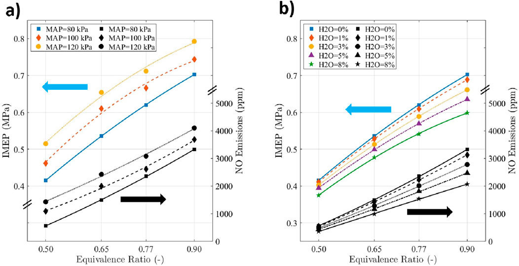
Figure 1. (a) IMEP and NO emissions at various MAP and
The benefit of increasing MAP is countered by the rise in NO emissions. Under an equivalence ratio of 0.9, the NO emissions increase by 11%, and 23% when the MAP increases from 80 kPa to 100 kPa and 120 kPa, respectively. This was because of the increase in in-cylinder pressure due to higher charge density for higher MAP values, which increases the turbulence intensity, consequently decreasing the combustion duration captured by Equation 1. Thus, it increases the in-cylinder temperature, which could be mitigated by decreasing the equivalence ratio. Under naturally aspirated conditions (MAP = 80 kPa), the NO emissions were reduced by 30%, 55% and 83% when the equivalence ratio was reduced from 0.9 to 0.77, 0.65, and 0.5, respectively; as was the load (Figure 1a). This could be due to the reduction in the in-cylinder temperature for leaner hydrogen-with-air mixtures. At an MAP of 80 kPa and an
3.2 Exergy analysis
Because hydrogen’s high reactivity and simple molecular structure differ greatly from hydrocarbon fuels, this section analyzes the exergy transfer to work, heat, irreversibility, and exhaust of a hydrogen SI engine at various water additions, manifold air pressures, equivalence ratios, and compression ratios. In Figure 2, the instantaneous exergy contributors of work, heat, and combustion irreversibility are presented as a function of crank angle from intake valve closing (IVC) to exhaust valve opening (EVO). During compression, the thermo-mechanical exergy increases as the in-cylinder pressure and temperature rise, whereas the exergy attributed to heat transfer remains insignificant. With the start of combustion at 10° crank angle (degrees) before top dead center (CA bTDC), the chemical exergy decreases significantly due to the fuel being burned, while the thermo-mechanical exergy increases as the chemical exergy is converted to mechanical exergy during combustion. Similarly, the exergy transfer to heat increases as the in-cylinder temperature rises, continuing through the expansion process. At the end of combustion, the total in-cylinder exergy decreases due to exergy transfers to work, heat, and combustion-related irreversibility. The remaining total in-cylinder exergy at EVO is defined as the exergy available at exhaust, as the in-cylinder pressure and temperature are still higher than those of the dead state.
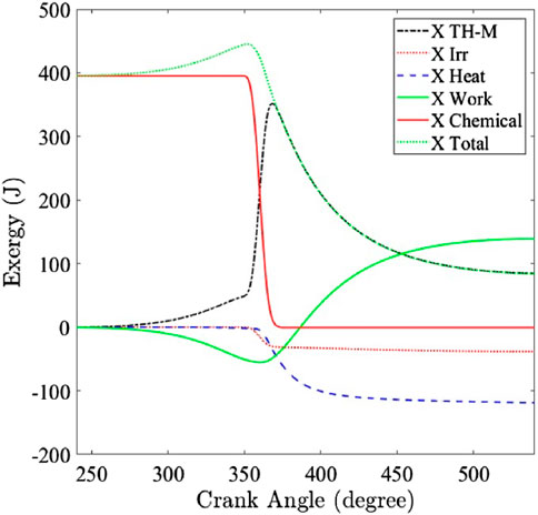
Figure 2. In-cylinder exergy split from intake valve closing (IVC) to exhaust valve opening (EVO) at a spark timing of 10° CA bTDC (MAP = 80 kPa, CR = 11.5).
Figure 3 shows the exergy split ratio defined as the proportion of the exergy transfer to work, heat, irreversibility, and exhaust, relative to the corresponding intake exergy. It can be seen from Figure 3 that in all presented cases, the largest exergy contributor is the transfer to reversible work. As the mixture becomes leaner, the exergy transfer to work increases. Under naturally aspirated conditions (MAP = 80 kPa), the exergy transfer to work increased by 4%, 7%, 8%, and 10% when the
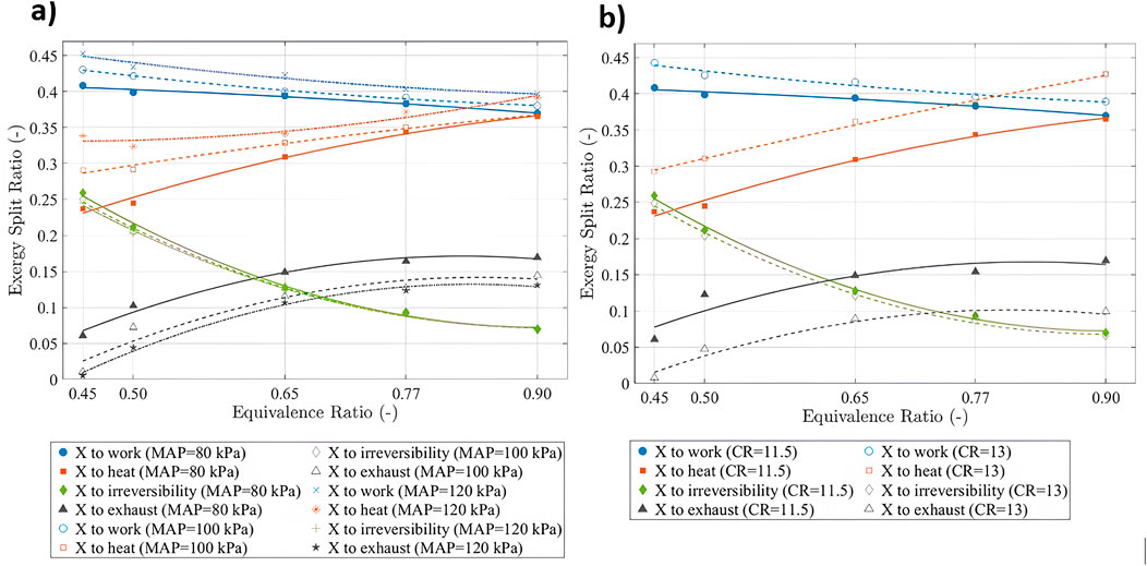
Figure 3. Exergy split ratio to work, heat, irreversibility, and exhaust at (a) various
In contrast, it can be seen from Figure 3a that the exergy transfer to heat decreases for leaner mixtures due to a drop in in-cylinder energy content (less fuel), which in turn lowers the in-cylinder temperature, reducing the temperature difference between the mixture and the chamber wall. Under naturally aspirated conditions (MAP = 80 kPa), the exergy transfer to heat decreased by 6%, 15%, 32%, and 35% when the
Figure 3a also shows that increasing MAP values increases the exergy transfer to work and heat. Under an
3.3 Water effect on exergy split to work, heat, irreversibility, and exhaust
Water injection reduces NO emissions, but the effect on the exergy split into work, heat, irreversibility, and exhaust must also be understood. The chemical exergy decreases proportionally to the mass fraction burned and decreases progressively as combustion occurs. The reducing slope of chemical exergy during combustion of Figure 4 shows that adding water to hydrogen combustion increases the combustion duration due to the decrease in laminar flame speed (LFS) and the increase in the heat capacity of the in-cylinder mixture due to the slower combustion process. The exergy transfer to work and heat shown in Figures 5a,b, respectively, decreases with higher water additions, primarily due to the high specific heat capacity of water. The exergy to heat at EVO was reduced by 2%, 15%, and 23% for 3%, 5%, and 8% water additions, respectively. Even though the heat transfer decreased, it did not divert the remaining exergy to work. Additionally, the exergy transfer to work at EVO decreases by 5%, 9%, and 14% for 3%, 5%, and 8% water addition, respectively. In contrast, as shown in Figure 5c, the exergy transfer to combustion-related irreversibility increases with water addition, with increases of 2%, 4%, and 9% at EVO for 3%, 5%, and 8% water additions, respectively. This could be due to the increase in entropy generation due to the rise of product entropy and reduction of the in-cylinder temperature with water addition (Rrustemi et al., 2025a).
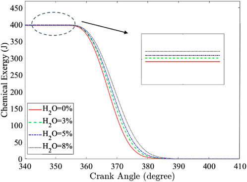
Figure 4. Hydrogen/air chemical exergy at different water additions for the naturally aspirated condition under an
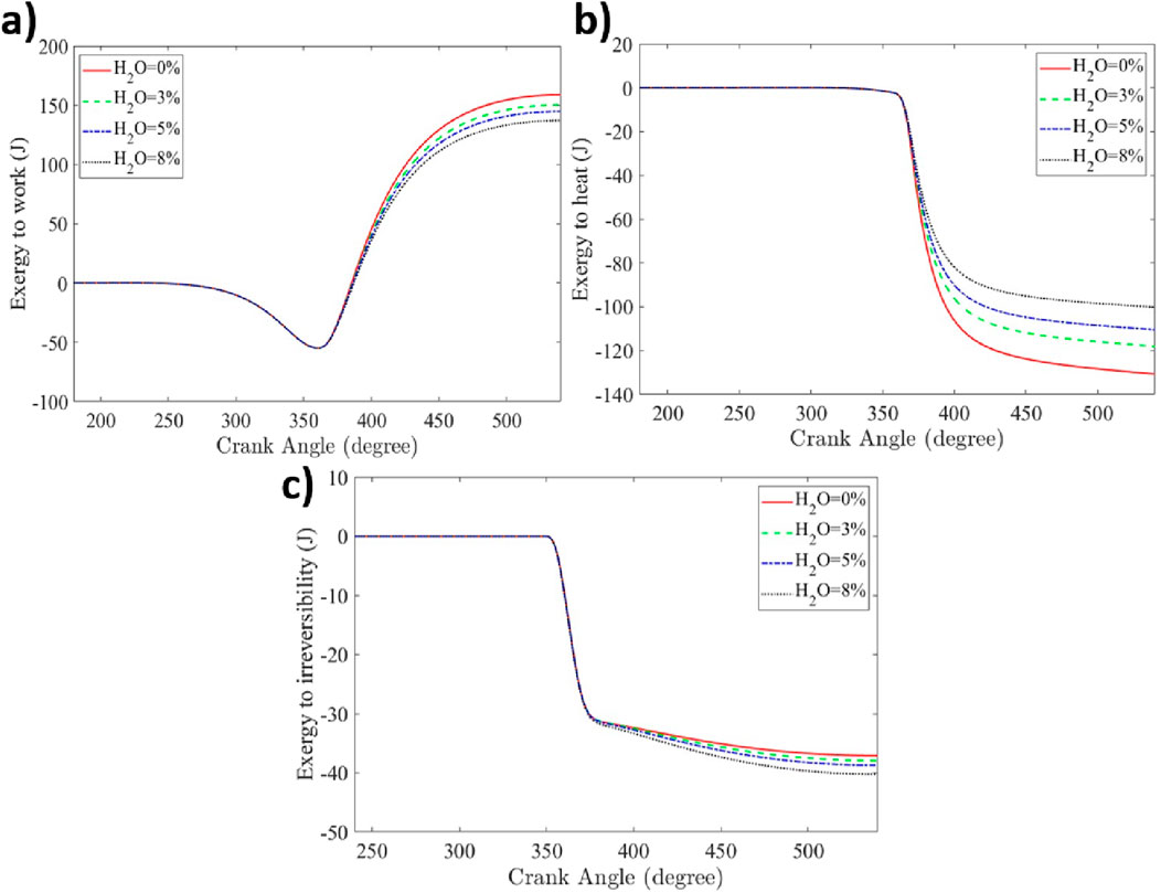
Figure 5. The exergy split to (a) work; (b) heat; (c) irreversibility for
Figure 6 shows that as water addition increases, the exergy transfer to work decreases due to the reduced in-cylinder pressure. For an
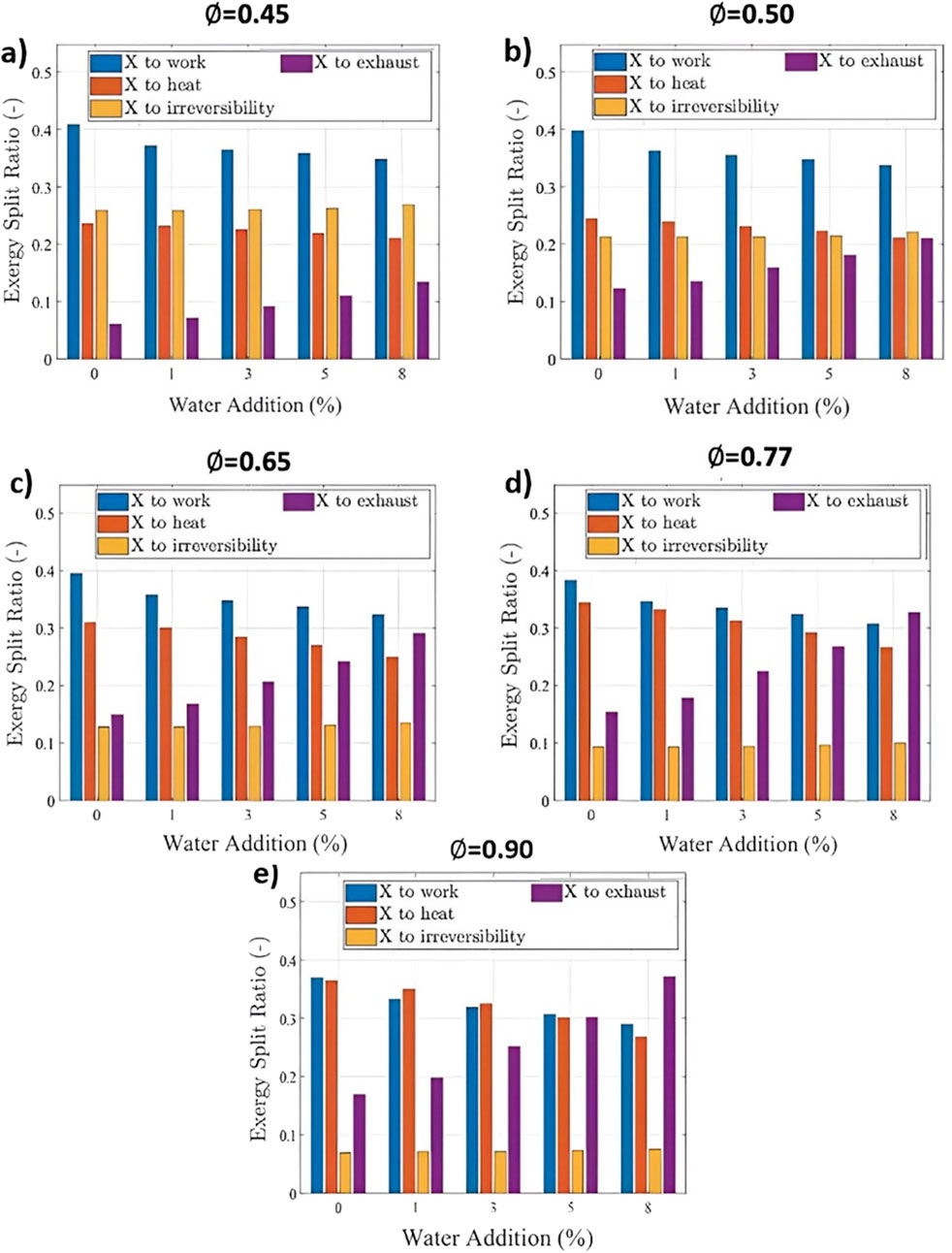
Figure 6. The exergy split ratio for a lean-burn hydrogen engine at various water additions and
4 Conclusion
A two-zone hydrogen combustion was used to identify the exergy transfer to work, heat, irreversibility, and exhaust of a boosted lean-burn hydrogen SI engine with water addition. Increasing manifold air pressure boosts the performance of the hydrogen SI engine but also increases NO emissions. NO emissions were mitigated by reducing the equivalence ratio and by water injection. Water injection effectively and significantly reduced NO emissions, but it came at the cost of reduced IMEP, requiring optimization between performance and emissions. For an equivalence ratio of 0.9 under naturally aspirated conditions with 1% water addition, NO emissions decreased by 6% with a 2% IMEP decrease. The analysis was achieved using the second law of thermodynamics to identify and quantify the exergy transfer to work, heat, irreversibility, and exhaust at various MAPs, equivalence ratios, compression ratios, and water additions. The exergy transfer to work increases with reducing equivalence ratio, as the exhaust enthalpy is diverted into useful work. However, the exergy split to combustion-related irreversibility also increases due to the reduced amount of hydrogen fuel at lower equivalence ratios. For naturally aspirated conditions at an equivalence ratio of 0.45, approximately 26% of the input exergy was transferred to combustion irreversibility, limiting the maximum possible efficiency to 74%. Additionally, increasing the MAP and compression ratio was shown to increase exergy transfer to heat and work, leaving less exergy to be expelled by the exhaust. The exergy transfer to combustion irreversibility was not significantly affected by the MAP or compression ratio. Adding water to the hydrogen SI engine decreased the exergy transfer to work and heat due to slower combustion, which was caused by the increased heat capacity of the hydrogen/air mixture with water addition. In contrast, exergy transfer to irreversibility increased because of lower in-cylinder temperatures. The remaining exergy was expelled through the exhaust, and this increased with higher water additions. For an equivalence ratio of 0.45 with 5% water addition, the exergy transfer to heat and work decreases by 12% and 7%, respectively. In contrast, the exergy transfer to combustion-related irreversibility and exhaust increases by 2% and 81%, respectively.
This study considered the exergy transfer to work, heat, combustion irreversibility, and exhaust to indicate their relative importance, but it could not capture the spatial effects of water addition on in-cylinder mixture formation, which would require more advanced multidimensional modeling. The aim was to understand how to manage resources to maximize work output while minimizing energy input and emissions. A hydrogen SI engine requires an increase in IMEP to compete with gasoline engines, which can be achieved by increasing the MAP or the compression ratio. Hence, the need to understand the exergy split into work, heat, irreversibility, and exhaust. Finally, it can be highlighted that water addition reduces NO emissions in a hydrogen-fueled SI engine and has further potential to optimize the exhaust exergy. Although the combustion model and exergy analysis in this study were developed for hydrogen, the methodology is also applicable to the optimization of other alternative-fueled SI engines. Exergy analysis of different fuels could reveal opportunities to improve engine thermal efficiency through the application of second-law-based engine control strategies.
Data availability statement
The raw data supporting the conclusions of this article will be made available by the authors, without undue reservation.
Author contributions
DR: Data curation, Formal Analysis, Investigation, Methodology, Software, Validation, Visualization, Writing – original draft. LG: Conceptualization, Methodology, Writing – review and editing. CA: Conceptualization, Methodology, Supervision, Writing – review and editing.
Funding
The author(s) declare that no financial support was received for the research and/or publication of this article.
Conflict of interest
The authors declare that the research was conducted in the absence of any commercial or financial relationships that could be construed as a potential conflict of interest.
Generative AI statement
The author(s) declare that no Generative AI was used in the creation of this manuscript.
Any alternative text (alt text) provided alongside figures in this article has been generated by Frontiers with the support of artificial intelligence and reasonable efforts have been made to ensure accuracy, including review by the authors wherever possible. If you identify any issues, please contact us.
Publisher’s note
All claims expressed in this article are solely those of the authors and do not necessarily represent those of their affiliated organizations, or those of the publisher, the editors and the reviewers. Any product that may be evaluated in this article, or claim that may be made by its manufacturer, is not guaranteed or endorsed by the publisher.
References
Abotabik, M., Meyer, R., and Proctor, C. (2020). “Exergy based optimal controller design of a spark-ignition internal combustion engine,”. Technical Paper 2020-01-0250. Detroit, MI: SAE International. doi:10.4271/2020-01-0250
Berckmüller, M., Rottengruber, H., Eder, A., Brehm, N., Elsässer, G., Müller-Alander, G., et al. (2003). “Potentials of a charged SI-Hydrogen engine,”. Technical Paper 2023-01–3210. Pittsburgh, PA: SAE International. doi:10.4271/2003-01-3210
Bleechmore, C., and Brewster, S. (2007). Dilution strategies for load and NOx management in a hydrogen fuelled direct injection engine, Rosemont, IL: SAE International, Technical Paper 2007-01–4097. doi:10.4271/2007-01-4097
Boretti, A. (2024). Water injection strategies to control gas temperatures in hydrogen–air internal combustion engines. J. Braz Soc. Mech. Sci. Eng. 46, 54. doi:10.1007/s40430-023-04623-x
Caton, J. A. (2000). A review of investigations using the second law of thermodynamics to study internal-combustion engines, Detroit, MI: SAE International, Technical Paper 2000-01–1081. doi:10.4271/2000-01-1081
Caton, J. A. (2012). Exergy destruction during the combustion process as functions of operating and design parameters for a spark-ignition engine. Int. J. Energy Res. 36, 368–384. doi:10.1002/er.1807
Conte, E., and Boulouchos, K. (2005). A quasi-dimensional model for estimating the influence of hydrogen-rich gas addition on turbulent flame speed and flame front propagation in IC-SI engines. J. ENGINES 1. doi:10.4271/2005-01-0232
Duva, B. C., and Toulson, E. (2022). Unstretched unburned flame speed and burned gas Markstein length of diluted hydrogen/air mixtures. Int. J. Hydrog. Energy 47, 9030–9044. doi:10.1016/j.ijhydene.2021.12.217
Gürbüz, H., and Akçay, İ. H. (2021). Evaluating the effects of boosting intake-air pressure on the performance and environmental-economic indicators in a hydrogen-fueled SI engine. Int. J. Hydrog. Energy 46, 28801–28810. doi:10.1016/j.ijhydene.2021.06.099
Gürbüz, H., and Gülcan, H. E. (2025). Energy, exergy, and exergoeconomic analysis of the use of hydrogen, LPG, and gasoline in an air-cooled SI engine running at stoichiometric conditions. Int. J. Hydrog. Energy 138, 1170–1179. doi:10.1016/j.ijhydene.2025.03.226
Hunzinger, N., Rothe, M., Spicher, U., Gegg, T., Rieber, M., Klimmek, A., et al. (2006). “Quasi-dimensional combustion simulation of a Two- stroke engine. Technical Paper 2006-32–0062. San Antonio, TX: SAE International, 2006. doi:10.4271/2006-32-0062
Knizley, A. A., Srinivasan, K. K., Krishnan, S. R., and Ciatti, S. A. (2012). Fuel and diluent effects on entropy generation in a constant internal energy–volume (uv) combustion process. Energy 43, 315–328. doi:10.1016/j.energy.2012.04.024
Knop, V., Benkenida, A., Jay, S., and Colin, O. (2008). Modelling of combustion and nitrogen oxide formation in hydrogen-fuelled internal combustion engines within a 3D CFD code. Int. J. Hydrog. Energy 33, 5083–5097. doi:10.1016/j.ijhydene.2008.06.027
Krebs, S., and Biet, C. (2021). Predictive model of a premixed, lean hydrogen combustion for internal combustion engines. Transp. Eng. 5, 100086. doi:10.1016/j.treng.2021.100086
Krishnamoorthi, M., Malayalamurthi, R., He, Z., and Kandasamy, S. (2019). A review on low temperature combustion engines: performance, combustion and emission characteristics. Renew. Sustain Energy Rev. 116, 109404. doi:10.1016/j.rser.2019.109404
Krishnanunni, J., Bhatia, D., and Das, L. M. (2017). Experimental and modelling investigations on the performance and emission characteristics of a single cylinder hydrogen engine. Int. J. Hydrog. Energy 42, 29574–29584. doi:10.1016/j.ijhydene.2017.10.018
Lee, S., Kim, Y., Lee, J., Kim, K., Lee, S., Min, K., et al. (2023). Energy and exergy analyses of hydrogen-fueled spark ignition engine with various air excess ratios and ignition timings. Fuel 349, 128588. doi:10.1016/j.fuel.2023.128588
Li, R. C., Zhu, G. G., and Men, Y. (2021). A two-zone reaction-based combustion model for a spark-ignition engine. Int. J. Engine Res. 22, 109–124. doi:10.1177/1468087419841746
Ma, F., Liu, H., Wang, Y., Wang, J., Ding, S., and Zhao, S. (2008). A quasi-dimensional combustion model for SI engines fuelled by hydrogen enriched compressed natural gas. Energy Procedia 1, 1633. doi:10.4271/2008-01-1633
Mangave, P. P., Pawar, N. D., Patil, R. S., Patil, V. V., and Kumar, S. (2025). Energy and exergy analysis of a SI engine fueled with anisole and isobutyl acetate with super-premium gasoline. Proc. Inst. Mech. Eng. Part C J. Mech. Eng. Sci. 239, 2202–2216. doi:10.1177/09544062241296924
Mohamed, M., Biswal, A., Wang, X., Zhao, H., Harington, A., Hall, J., et al. (2024). Exploring the benefits of hydrogen-water injection technology in internal combustion engines: a rigorous experimental study. Int. J. Engine Res. 26, 724–740. doi:10.1177/14680874241288624
Mortimer, J., Poursadegh, F., Brear, M., Yoannidis, S., Lacey, J., and Yang, Y. (2023). Extending the knock limits of hydrogen DI ICE using water injection. Fuel 335, 126652. doi:10.1016/j.fuel.2022.126652
Nishida, K., Takagi, T., and Kinoshita, S. (2002). Analysis of entropy generation and exergy loss during combustion. Proc. Combust. Inst. 29, 869–874. doi:10.1016/S1540-7489(02)80111-0
Pozzato, G., Rizzo, D. M., and Onori, S. (2022). Mean-value exergy modeling of internal combustion engines: characterization of feasible operating regions. J. Dyn. Syst. Meas. Control 144, 061009. doi:10.1115/1.4053945
Rakopoulos, C., and Giakoumis, E. (2006). Second-law analyses applied to internal combustion engines operation. Prog. Energy Combust. Sci. 32, 2–47. doi:10.1016/j.pecs.2005.10.001
Rakopoulos, C. D., Michos, C. N., and Giakoumis, E. G. (2008). Availability analysis of a syngas fueled spark ignition engine using a multi-zone combustion model. Energy 33, 1378–1398. doi:10.1016/j.energy.2008.05.007
Razmara, M., Bidarvatan, M., Shahbakhti, M., and Robinett, R. D. (2016). Optimal exergy-based control of internal combustion engines. Appl. Energy 183, 1389–1403. doi:10.1016/j.apenergy.2016.09.058
Rrustemi, D. N., Ganippa, L. C., Megaritis, T., and Axon, C. J. (2024). New laminar flame speed correlation for lean mixtures of hydrogen combustion with water addition under high pressure conditions. Int. J. Hydrog. Energy 63, 609–617. doi:10.1016/j.ijhydene.2024.03.177
Rrustemi, D. N., Ganippa, L. C., Megaritis, T., and Axon, C. J. (2025a). Predicting hydrogen engine performance with water addition using a two-zone thermodynamic model. Fuel 386, 134137. doi:10.1016/j.fuel.2024.134137
Rrustemi, D. N., Ganippa, L. C., and Axon, C. J. (2025b). Exergy analysis of the lean-burn hydrogen-fuelled engine. Energy 314, 134110. doi:10.1016/j.energy.2024.134110
Salvi, B. L., and Subramanian, K. A. (2022). A novel approach for experimental study and numerical modeling of combustion characteristics of a hydrogen fuelled spark ignition engine. Sustain Energy Technol. Assess. 51, 101972. doi:10.1016/j.seta.2022.101972
Saxena, S., Shah, N., Bedoya, I., and Phadke, A. (2014). Understanding optimal engine operating strategies for gasoline-fueled HCCI engines using crank-angle resolved exergy analysis. Appl. Energy 114, 155–163. doi:10.1016/j.apenergy.2013.09.056
Şöhret, Y., Gürbüz, H., and Akçay, İ. H. (2019). Energy and exergy analyses of a hydrogen fueled SI engine: effect of ignition timing and compression ratio. Energy 175, 410–422. doi:10.1016/j.energy.2019.03.091
Verhelst, S. (2014). Recent progress in the use of hydrogen as a fuel for internal combustion engines. Int. J. Hydrog. Energy 39, 1071–1085. doi:10.1016/j.ijhydene.2013.10.102
Wang, X., Sun, B., and Luo, Q. (2019). Energy and exergy analysis of a turbocharged hydrogen internal combustion engine. Int. J. Hydrog. Energy 44, 5551–5563. doi:10.1016/j.ijhydene.2018.10.047
Woschni, G. (1967). A universally applicable equation for the instantaneous heat transfer coefficient in the internal combustion engine. Technical Paper 1967-67–0931. SAE International. 1. 670931. doi:10.4271/670931
Xu, P., Ji, C., Wang, S., Cong, X., Ma, Z., Tang, C., et al. (2020). Effects of direct water injection on engine performance in engine fueled with hydrogen at varied excess air ratios and spark timing. Fuel 269, 117209. doi:10.1016/j.fuel.2020.117209
Younkins, M., Wooldridge, M. S., and Boyer, B. A. (2015). Port injection of water into a DI hydrogen engine. Technical Paper 2015-01–0861. Detroit, MI: SAE International. doi:10.4271/2015-01-0861
Zaccardi, J.-M., and Pilla, G. (2019). Hydrogen as a combustion enhancer for highly efficient ultra-lean spark-ignition engines, Kyoto, JP: SAE International, Technical Paper 2019-01–2258. doi:10.4271/2019-01-2258
Nomenclature
Symbols
c specific heat (J/kgK)
σ Stefan–Boltzmann constant (5.67 × 10⁻⁸ W/m2K4)
h specific enthalpy (J/kg)
i species index
j environmental species index
k kinetic energy (m2/s2)
l length (m)
m mass (kg)
μ chemical potential (J/mol)
n number of moles (mol)
P pressure (Pa)
∅ equivalence ratio
Q heat (J)
R universal gas constant (8.314 J/mol K)
S entropy (J/K)
SL Laminar flame speed (m/s)
T temperature (K)
θ crank angle (degrees)
U specific internal energy (J)
u′ turbulent intensity (m/s)
V volume (m3)
v stoichiometric coefficient
X exergy (J)
Acronyms
bTDC before top dead centre
CA crank angle
CR compression ratio
EGR exhaust gas recirculation
EVO exhaust valve opening (crank angle)
H2O water vapor
ICE internal combustion engine
IMEP indicated mean effective pressure (Pa)
ITE indicated thermal efficiency (%)
IVC intake valve closing (crank angle)
MAP manifold air pressure (Pa)
MBT maximum brake torque
NO nitric oxide
NOx oxides of nitrogen
Subscripts
0 dead state
b burn
chem chemical
Exh exhaust
e entrained
Heat heat
ht heat transfer
Irr irreversibility
TM thermo-mechanical
TM restricted dead state
Work work
Keywords: combustion, efficiency, entropy, hydrogen, ice, water addition
Citation: Rrustemi DN, Ganippa LC and Axon CJ (2025) Hydrogen with water addition: an exergy analysis of the internal combustion engine. Front. Mech. Eng. 11:1704197. doi: 10.3389/fmech.2025.1704197
Received: 12 September 2025; Accepted: 13 October 2025;
Published: 19 November 2025.
Edited by:
Ming Jia, Dalian University of Technology, ChinaReviewed by:
Aleksandar Ašonja, Business Academy University (Novi Sad), SerbiaAbhishek Priyam, SVKM'S NMIMS University, India
Copyright © 2025 Rrustemi, Ganippa and Axon. This is an open-access article distributed under the terms of the Creative Commons Attribution License (CC BY). The use, distribution or reproduction in other forums is permitted, provided the original author(s) and the copyright owner(s) are credited and that the original publication in this journal is cited, in accordance with accepted academic practice. No use, distribution or reproduction is permitted which does not comply with these terms.
*Correspondence: C. J. Axon, Q29saW4uQXhvbkBicnVuZWwuYWMudWs=
†ORCID: D.N. Rrustemi, orcid.org/0000-0002-9824-8332; L.C. Ganippa, orcid.org/0000-0001-6505-8447; C.J. Axon, orcid.org/0000-0002-9429-8316