 Arvind Mukundan1,2,3†
 Bhardwaj Shastri4†
 Riya Karmakar1,3Pratham Chandraskhar Gade5
 Hsiang-Chen Wang1,6*
- 1Department of Mechanical Engineering, National Chung Cheng University, Chiayi, Taiwan
- 2Department of Biomedical Imaging, Chennai Institute of Technology, Chennai, Tamil Nadu, India
- 3School of Engineering and Technology, Sanjivani University, Sanjivani Factory, Kopargaon, Maharashtra, India
- 4Raumfahrt Abteilung, Zentrum für Telematik e.V, Würzburg, Germany
- 5Information Technology Department, Sanjivani College of Engineering, Kopargaon, Maharashtra, India
- 6Department of Technology Development, Hitspectra Intelligent Technology Co., Ltd., Kaohsiung, Taiwan
Introduction: Venus, a celestial entity historically associated with Earth, has a planetary atmosphere characterized as hellish. Throughout the history of space exploration, a finite number of spacecraft have been sent to examine this mysterious planet. Of the many journeys to our celestial satellite, only about twelve have successfully communicated with the planetary surface. The landers with the longest operational lifespans functioned for just a little while, succumbing to the intense and relentless mix of severe heat and pressure. The National Aeronautics and Space Administration’s Jet Propulsion Laboratory (NASA-JPL) is currently evaluating a mission proposal to revisit the planet Venus.
Methods: The Automaton Rover for Extreme Environment (AREE) mission concept aims to perform prolonged exploration of the terrain of our adjacent celestial body, employing wind-powered automatons and mechanical devices, with the objective of functioning for extended durations rather than mere minutes. As the rover navigates the Venusian surface and relays data to an orbiting satellite, it is essential for it to simultaneously detect and recognize any obstacles that could hinder its advancement.
Results: To facilitate the innovative mission concept of AREE, the primary mechanism utilized for the identification and navigation of perilous situations during the operational lifespan of the prospective rover will be designated as the Hazard Avoidance and VEhicular Navigation System (HAVEN). This research study will concentrate on the design concept of the HAVEN sensor, which seeks to augment the rover’s capabilities by identifying diverse impediments, such as rocks, fissures, and slopes.
Discussion: By accurately detecting and recognizing these challenges, the rover will navigate Venus’s rough terrain and enhance its exploration endeavors, hence enabling the acquisition of significant observational data.
1 Introduction
1.1 About
This work provides the author’s response to the challenge presented by NASA Tournament Lab, in partnership with NASA-JPL, regarding the development of a mechanical sensor for obstacle avoidance in the AREE rover. The objective is to create a sensor that is not dependent on susceptible electrical systems. This paper provides an overview of the mission goal, design and development, external environment analysis, technical budgets, and risk assessment associated with HAVEN.
1.2 Primary objective
Recent advancements further justify HAVEN’s electronics-free front end while elucidating material and load-case selections. At the device level, ferroelectric AlScN non-volatile memory functioning at 600 °C exhibits data retention comparable to near-Venus temperatures, indicating a supplementary approach for back-end data logging or mission redundancy, particularly if few electronics are situated behind thermal shielding (Pradhan et al., 2024). NASA’s 2024–2025 evaluations of long-duration Venus landers and the VISTA/DAVINCI engineering sensor initiative highlight the technological readiness for extended operation under 9.2 MPa and about 730 K conditions (Raut et al., 2022). Recent field deployments in planetary robotics underscore the effectiveness of strong autonomy and multi-robot techniques for navigating hazardous terrains, which feed our validation protocols (Martinez et al., 2025). Regarding materials, high-temperature creep and fracture data for Ni-based superalloys, along with contact stability analyses for GaN HEMTs at increased temperatures, furnish bounding properties and tribo-thermal considerations for springs, limiters, and interfaces in HAVEN’s drivetrain (Domínguez et al., 2025; Niroula et al., 2024). Venus is the planet that is nearest to Earth in terms of distance, size, and mass. Its radius is approximately 5% smaller than Earth’s (Taylor et al., 2018). The uncompressed density of Venus is roughly identical to that of Earth, suggesting that both planets have a similar structure and composition. Venus possesses a compact atmosphere that is predominantly composed of carbon dioxide and is covered by dense clouds of sulfuric acid (Airey et al., 2015). At the average planetary radius (APR), the atmospheric pressure is approximately 9.2 MPa (MPa) and the temperature is around 730 K (K) as a result of the significant atmospheric density and strong greenhouse effect (Seiff et al., 1985). Venus lacks an inherent magnetic field to protect its upper atmosphere from the solar wind (Martinecz et al., 2009). The absence of a magnetic cavity leads to a highly organized plasma environment, resembling the conditions observed at Mars and comets. This environment is defined by the direct contact between the solar wind and the upper part of the ionosphere. The Automaton Rover for Extreme Environments (AREE) suggests a significant change in approach, moving away from electronics and towards a completely mechanical system. This would allow for the exploration of the most extreme environments in the solar system across extended distances (Sauder et al., 2017a; Sauder et al., 2017b; Alva et al., 2022). The primary objective of the HAVEN mission is to facilitate the navigation of the AREE rover across obstacles encountered on the surface of Venus throughout its anticipated operational duration of 6 months. Based on the design and requirements outlined by the AREE rover, it is necessary for the HAVEN sensor to satisfy the following functional requirements:
a. The sensor must demonstrate consistent responsiveness when faced with inclines exceeding a 30-degree angle, whether they are uphill or downhill.
b. The sensor must possess a reliable capability to detect and react to obstacles with a height exceeding 0.35 m, such as rocks.
c. The sensor will not activate in response to rocks that are less than 0.3 m in height.
d. The sensor must demonstrate consistent responsiveness when detecting holes or valleys with a depth exceeding 0.35 m, regardless of their breadth, with the exception of thin valleys.
e. The sensor will not activate for holes that have a depth of less than 0.3 m.
f. Assured detection for apertures with minimum inscribed diameter Dap ≥ 0.10 m; a non-response band for Dap ≤ 0.06 m to suppress nuisance triggers; and a gray band 0.06 < Dap< 0.10 m where a trigger occurs only with corroboration any one of: local slope ≥15°, rack vertical drop ≥8 mm within one stroke, or spinner under-support ≥ one-quarter revolution. Post-trigger hysteresis/reset requires either Dap< 0.04 m sustained over ≥10 mm of forward travel or two consecutive spinner-support confirmations before re-engagement. The thresholds are tied to geometry via spinner spacing S and pusher nose radius rp (with Dap, assured ≳ S − 2rp) and will be verified using calibrated slot-gauge and stepped-gap fixtures.
2 Materials and methods
2.1 HAVEN’s design concept
HAVEN’s uniqueness lies in its integration of traditional mechanisms into a singular, autonomous hazard-avoidance system specifically engineered for the Venusian environment. Previous planetary rovers have utilized electronic or electromechanical sensors integrated with software-based navigation systems. In contrast, HAVEN exemplifies mechanical autonomy, wherein sensing, decision-making, and actuation are achieved through a sequence of mechanical interactions, independent of vulnerable electronics. The multi-stage transmission system comprises torque limiters, dog clutches, spur and bevel gears, and a scotch-yoke actuator, which together form the fail-safe logic system that detects obstacles, isolates overloads, and initiates avoidance maneuvers. The design is a functional mechanical logic circuit wherein the flow of energy and information relies on controlled motion rather than electrical impulses. Furthermore, to attain structural integrity and fatigue resistance at temperatures of 730 K and loads of 9.2 MPa, HAVEN engineers its mechanism and optimizes its materials (Ti-SF61, Ti-6Al-4V, Inconel X-750) for high-temperature applications. The integration of mechanism design, material selection, and environmental compatibility constitutes the primary novelty of HAVEN, enabling modular operation on the surface of Venus, devoid of electronics and the necessity for recharging.
Figure 1a depicts the isometric view, whereas Figure 1b presents the front view of the object referred to as HAVEN. The sensor is equipped with a mechanism box and three extended arms, consisting of one pusher and two spinners. These components enable the sensor to effectively detect and navigate obstacles, as well as identify slopes and valleys. In situations where it becomes necessary to go around an obstacle, hill, or valley, the extension of the rover’s arms initiates a mechanical signal to the mechanism box. This signal, in turn, activates the reverse drive pin of the rover. Therefore, the rover will come to a halt, briefly reverse its direction, and subsequently adjust its trajectory accordingly.

Figure 1. HAVEN concept design. (a) isometric view and (b) front view of HAVEN.
Figure 2 illustrates the conceptual design of the AREE, featuring the attachment of HAVEN on its front side. The device functions akin to a rover’s appendage, facilitating the identification of impediments that necessitate avoidance.

Figure 2. AREE concept design with HAVEN sensor.
HAVEN is used for exploration and development of various gear arrangements and mechanical components that harness mechanical power from rovers. The absence of electrical components poses a challenge in maintaining an operational environment at high temperatures on the surface of Venus. In order to safeguard the mechanism box from the Venusian atmosphere, it is proposed to employ a 2 mm thick sheet as an outer layer, as depicted in Figure 3a.
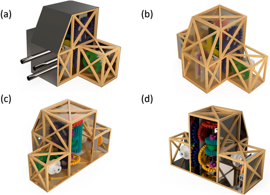
Figure 3. (a) Outer sheet cover of mechanism box, (b) and (c) different isometric views of the Truss structure of mechanism box, (d) Inner sheet cover of mechanism box.
Since the size of the HAVEN sensor is compact, it can be fitted in a other mini rover design in synergy with the other instruments such as on the Kalam Rover (Mukundan and Wang, 2023; Mukundan et al., 2023a; Mukundan et al., 2023b; Mukundan et al., 2023c; Mukundan et al., 2022). The truss structure will serve as the primary support for the mechanism box, with the outer sheet cover being affixed to it. The truss construction is specifically engineered to endure the various loads encountered during launch conditions, as well as the substantial pressure of approximately 93 bar exerted on the mechanism box while it is situated on the surface of Venus. The truss construction is composed of bars featuring a square cross-sectional area measuring 10 mm × 10 mm. X-cross connections are implemented with the purpose of enhancing the structural load-bearing capacity. Figures 3b,c depicts an isometric view of the truss structure within the mechanism box.
The mechanism box is comprised of an inner cover made of a sheet that is 1.5 mm in thickness. The primary function of this inner cover is to offer structural reinforcement for the mechanisms housed within the box, if needed. In addition to serving as a basis for internal mechanics, it also functions as a means of reinforcement for truss structures in carrying external loads. The inner sheet depicted in Figure 3d does not provide complete coverage for all interior sides of the mechanism box, in contrast to the outer sheet cover which fully covers all outside sides.
The AREE idea employs a wholly mechanical architecture for navigation and obstacle avoidance, enabling it to endure conditions of 730 K and 9.2 MPa. HAVEN functions as the front-end in this motion-control loop. The resultant displacement is transmitted (through the rack-and-pinion and gear train) to the scotch-yoke assembly when the sensor’s detecting components (pusher or spinner) encounter an obstacle, slope, or depression beyond the designated thresholds. The scotch-yoke functions as an electrical signal, utilizing its linear output to activate the reverse-drive pin on the rover, ceasing forward motion and initiating a brief reverse maneuver. Upon clearing the blockage, the transmission is reset via the torque limiter and clutch sequencing, allowing the rover to proceed along a modified route. HAVEN performs sensing and actuation functions by mechanical sequencing rather than software, aligning with the principle of AREE.
2.2 HAVEN’s working mechanism
Although less intricate, straightforward direct acting links can facilitate obstacle avoidance with fewer components, concentrating load and temperature exposure on a restricted number of pieces. The combination of high contact stress, time-dependent deformation, and friction from debris poses significant risks under Venus-like conditions (approximately 730 K and 9.2 MPa), subjecting chemically pure platinum to a heightened likelihood of creep, seizure, and irreversible misalignment. Multiphase transmission is employed in HAVEN, facilitating a multi-stage delivery of torque and motion across various gears and couplings. Ball-detent torque limiters connect upstream loads during an impact or jam, decoupling the load to safeguard the detecting module and facilitating automatic re-engagement; the dog clutch provides positive, slip-free transfer upon command, minimizing wear, while the scotch-yoke transforms rotary motion into controlled linear force on the reverse-drive pin, negating the necessity for spring deflection to exert the force. This partitioned architecture includes a network of mechanical fuses and conditioners that improve jamming tolerance and fault isolation while maintaining the necessary force margin for dependable actuation in extreme thermal-pressure conditions. HAVEN utilizes a mechanism consisting of bevel gears, spur gears, a rack and pinion mechanism, a slide gear mechanism, a scotch-yoke mechanism, springs, torque limiters, and a dog clutch. Figure 4 depicts a detailed anatomical representation of HAVEN’s mechanism. The entire sensor is comprised of two distinct mechanisms: (a) Triggering mechanism and (b) Detecting mechanism.
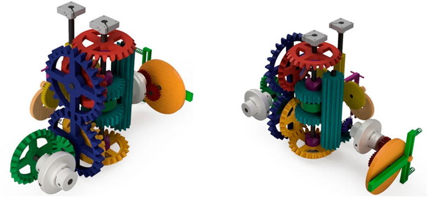
Figure 4. Anatomy view of HAVEN’s mechanism.
2.2.1 Triggering mechanism
The collection of mechanisms located on the rear side of the mechanism box is referred to as the triggering mechanism. These mechanisms, as their name implies, activate the necessary reverse drive pin to halt the forward movement of the rover and change its direction in order to avoid any unwanted path or barrier. Figure 5 displays the posterior and isometric perspectives of the triggering mechanism segment within the mechanism box. Further discussion will focus on the components utilized in the triggering process.

Figure 5. (A) 3-D design of the transmitter module and (B) Block diagram of the transmitter module.
The gears within a gearbox might be likened to the wheels within a crossing, belt pulley system. Gears offer the benefit of preventing slippage during high-speed revolutions and in high-temperature environments due to the presence of teeth. Geared devices have the ability to modify the speed, torque, and direction of a power source by utilizing their gear ratio. As a result, they can be regarded as a basic mechanical device that provides a mechanical advantage. The triggering mechanism employs four sets of straight-cut bevel gears and three sets of straight-cut spur gears. The primary rationale for employing straight-cut gear types in this context is to mitigate the presence of axial thrust on the gear axis. This necessitates the use of suitable thrust bearings, which may contribute to an increase in the mass of the sensor.
A torque limiter is an automated overload clutch that offers machine safeguarding in the event of jamming load circumstances. A mechanical torque limiter offers superior response times and enhanced protection compared to conventional electrical solutions in situations with high crash rates. Among the several types of disconnects available, we will utilize a customized ball detent type torque limitation that aligns with our specific sensor needs. This particular configuration is depicted in Figure 6a.

Figure 6. (a) Customized torque limiter, (b) Working principle, (c) Working of scotch-yoke mechanism Disengage condition (d) Working of scotch-yoke mechanism Engage condition, (e) Function of 2nd torque limiter from circuit by torque limiter, (f) Dog clutch, (g) Working of dog clutch Engage condition, (h) Working of dog clutch disengage condition, (i) Sliding gear transmission, (j) Slider, (k) Stand-by condition of triggering mechanism, (l) Engage conditions of triggering mechanism bevel gear (yellow) to slider (m) Engage conditions of triggering mechanism bevel gear (red) to slider.
Figure 6a illustrates a ball detent type torque limiter that transfers force by utilizing hardened balls positioned in detents on the shaft. These balls are secured in place by springs. An excessive torque causes the balls to be forced out of their detents, resulting in the separation of the shaft. Ball detent torque limiters differ from friction style or shear pin type torque limiters in that they offer a precise means of resetting the torque without requiring any external involvement. Upon reaching the predetermined torque limit, the clutch disengages, resulting in an abrupt decrease in torque. The clutch attempts to automatically re-engage at every 360 degrees of rotational rotation. Once the torque on both sides is equal, the clutch is prepared for action once more. Additional cycle sequences, such as a 180-degree rotation, are also provided. The triggering mechanism employs a pair of ball detent type torque limiters. In order to safeguard the operation of the rover in the event of a jamming issue, a torque limiter is positioned directly between the output shaft of the rover and the input shaft of the sensor. This torque limiter, depicted in Figure 4 as the green-colored bevel gear set, serves to protect the rover by ensuring that the mechanical power supply remains constant.
The Scotch-Yoke mechanism is a type of mechanism that converts rotational motion into linear motion, or vice versa, by use of a reciprocating motion (Al-Hamood et al., 2019; Arakelian et al., 2016; Sawyer et al., 2003). The reciprocating part of the scotch is connected directly to a sliding yoke that has a slot which interacts with a pin on the spinning part. Figures 6c,d depicts the utilization of a scotch-yoke mechanism in the sensor. The objective of employing this mechanism is to exert the necessary force on the reverse drive pin of the rover. The force exerted by the sliding yoke can be adjusted by rotating the scotch and by modifying the distance between the slot that links the scotch and the yoke, and the center of the scotch. Typically, a single rotation results in a complete reciprocating motion, which involves moving back and forth. However, the scotch-yoke mechanism employed in this case has been tailored to specific requirements.
Figure 6c depicts the mechanism in its stand-by position, also known as the disengage position. Upon receiving a mechanical signal from the detecting mechanism, the scotch rotates counterclockwise, causing the sliding yoke to go forward and exert the necessary force on the reverse drive pin of the rover. Next, the secondary torque limiter located in front of the mechanism depicted in Figure 6e becomes active. Once the reverse drive pin achieves its maximum displacement of 3cm, it will cause the torque limiter to get jammed. Consequently, the torque limiter will separate the scotch yoke mechanism from the remaining circuit. The tension springs are connected between the yoke and support to accumulate potential energy when the yoke goes forward. The energy is immediately discharged upon disengagement of the scotch-yoke mechanism. The torque limiter reactivates when the yoke returns to the stand-by position. The method continues to iterate until a mechanical signal indicates that an impediment is still obstructing the path.
A dog clutch is a clutch mechanism that connects two rotating shafts or components by an interference or clearance fit, rather than relying on friction (Aljawabrah and Lovas, 2023; Shiotsu et al., 2019; Duan, 2014). The clutch is engineered with two components that exert force on each other, resulting in synchronized rotation at a constant speed without any slippage. The design of the dog clutch utilized in the sensor is depicted in Figure 6F. The dog clutch facilitates the transmission of power between the main shaft and the output shaft by the use of a bevel gear and slider mechanism, as depicted in Figures 6g,h.
A slide gear mechanism is a transmission system including many sets of gears and shafts arranged in an organized manner (Chen and Zeng, 2019; Chen et al., 2018). The gear ratios are changed by sliding the gears along the splined shaft using a gear lever. Slide gear mechanism utilized in the sensor is depicted in Figure 6i. Figure 6j depicts the slider design, comprising two spur gears coupled by a modified ball bearing and equipped with a dog clutch on either side. The outer portion of the ball bearing is linked to a detecting mechanism that facilitates the reception of mechanical signals through the sliding of gears along the splined shaft. Ball bearings facilitate the movement of the slider along the rotating shaft, which is shared by both the slider and bevel gears. Transmission is done as soon as slider moves either up or down along the shaft and dog clutch is engage. The transmission process involves the utilization of a spur gear that is connected to a spline gear. From there, the power is transferred through bevel gears to a torque limiter, which ultimately reaches the scotch-yoke mechanism.
Figure 6k depicts the standby position of the triggering mechanism, in which the slider is in a neutral position relative to the shaft. In this configuration, the slider moves unrestrictedly along the shaft without any transmission. Transmission occurs when the slider travels either upward or downward.
Figure 6i depicts the transmission mechanism in which the slider goes downward and connects with a continuously revolving bevel gear (yellow) via a dog clutch. Figure 6m illustrates the transmission process in which the slider goes upwards and connects with a continuously rotating bevel gear (red) upon receiving a mechanical signal from the detecting mechanism.
2.2.2 Detecting mechanism
The assemblage of mechanisms on the front side of the mechanism box, which includes pushers and spinners, is referred to as the detecting mechanism. These devices, as their name implies, aid in identifying barriers, slopes, or valleys that must be avoided and transmit a mechanical signal to activate the triggering mechanism. Figure 7a displays an isometric perspective of the detection system.
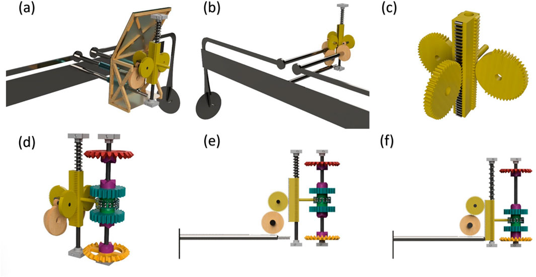
Figure 7. (a) Detecting mechanism, (b) Anatomy of detecting mechanism, (c) Rack and pinion system, (d) Connection between triggering and detecting mechanism, (e) Pusher–downward movement, (f) Pusher – upward movement.
The primary method of detection is accomplished by the utilization of a rack and pinion system, which is further reinforced by spur gears and compression springs. The rack is built with three sides, one of which is constantly engaged while the other two sides come into contact as needed, as depicted in Figures 7b,c.
Figure 7d illustrates the linkage between the triggering mechanism and the detecting mechanism. The outer portion of the slider’s bearing in the triggering mechanism is linked to the rack in the detecting mechanism via a rod. Therefore, the motion is transferred from the rack to the slider. Additionally, a compression spring is positioned above the rack to restore it to a neutral position if the rack moves in either an upward or downward direction.
A pusher is a straightforward device that utilizes a rack and pinion system to transmit motion to the main rack via a spur gear. A pusher is a shaft with a plate at one end to detect impediments and a linear gear (rack) arrangement at the other end. The inner end of the pusher is also reinforced by a compression spring, which ensures that the pusher remains in a neutral position during its movement. When an impediment makes contact with the pusher when the rover is going forward, a force of 150N is exerted on the pusher in the opposite direction. As a result of this reactionary force, the pusher moves in the opposite direction, causing the main rack to move downward and generating a mechanical signal, as depicted in Figures 7e,f. The compression spring stores energy as the pusher moves in a backward direction and releases it when the rover goes backward.
Placing a component with a length of approximately 0.606 m at a height of 0.35m, enables the measurement of slopes with an angle more than or equal to 30° and rocks with a height greater than or equal to 0.35 m. Therefore, this notion is applicable to both pushers and spinners. The pusher is designed to identify a front slope of 30° and rocks that are at least 0.35 m in height, as depicted in Figures 8a,b, respectively.

Figure 8. (a) Pusher - 30° front slope, (b) Pusher - Obstacle >0.35 m and (c) detecting process - spinner.
The spinner aids in identifying impediments such as inclines, depressions, potholes, and rocks that may be present along the wheel path. The procedure of detecting the spinner is illustrated in Figure 8c. One end of the spinner is connected to a spur gear, which transmits motion to the main rack. The other end of the spinner has a wheel with a diameter of 0.1m, which follows the surface in front. The Spinner operates on the same design principle as the Pusher.
The spinner is capable of detecting side slopes with an angle of 30° or greater, side valleys with an angle of 30° or greater, front valleys with an angle of 30° or greater, rocks that are at least 0.35 m high, and potholes with a depth of 0.35 m or greater. These features are illustrated in Figures 9a–e, respectively.
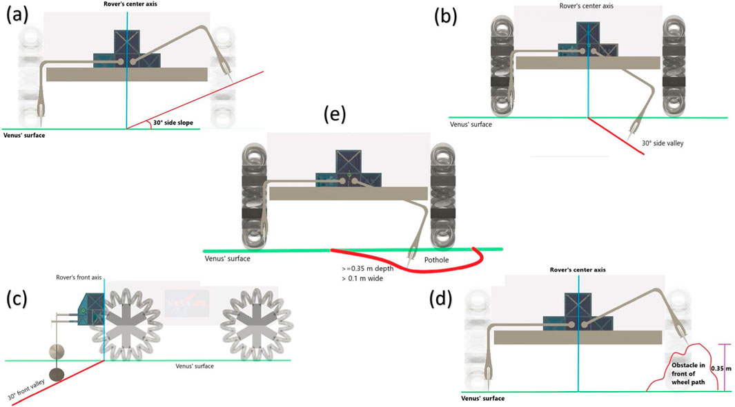
Figure 9. (a) Spinner - 30° side slope, (b) Spinner - 30° side valley, (c) Spinner - 30° front valley and (d) Spinner - Obstacle >0.35m., (e) Spinner detecting a pothole greater than 0.35 m in depth and greater than 0.1 m in width.
2.3 Materials
Titanium Ti-SF61 is a recently developed titanium alloy that belongs to the high temperature near alpha grade 6 category (Lu et al., 2015). Due to the presence of Yttrium, which produces thermally stable oxides, this material exhibits significant fatigue strength at high temperatures and exceptional resistance to creep. Ti-SF61 is the most sophisticated conventional titanium alloy designed for high temperatures. The chemical composition of Ti-SF61 is composed of titanium (Ti) with the following alloying elements: 5.9% aluminum (Al), 2.7% tin (Sn), 4% zirconium (Zr), 0.45% molybdenum (Mo), 0.35% silicon (Si), and 0.22% yttr. Ti6Al4V is a titanium alloy with a grade 5 designation, characterized by its alpha-beta structure (Raut et al., 2022; Pederson, 2002). It possesses a remarkable strength-to-weight ratio and exhibits exceptional resistance to corrosion, particularly at high temperatures. Titanium alloys are widely used in various applications, particularly in the aerospace sector and bio-mechanical applications, due to their low density and exceptional corrosion resistance. They are considered the workhorse among titanium alloys. Ti-SF61 is chosen for components directly exposed to the Venus atmosphere due to its superior creep resistance, better fatigue strength, and greater corrosion resistance compared to grade 5 Ti6Al4V. Ti6Al4V is chosen for interior components such as gears due to its excellent manufacturability. To prevent a decrease in the load capacity of springs at elevated temperatures, HAVEN utilizes springs composed of inconel alloy X-750. Alloy X-750 is a nickel-chromium alloy that can be strengthened through precipitation (Mamiya et al., 2016). It is commonly utilized for its ability to resist corrosion and oxidation, as well as its exceptional strength at elevated temperatures. Alloy X-750 exhibits exceptional characteristics even at extremely low temperatures, including cryogenic conditions (Wang et al., 2013). The rationale for excluding alloy X-750 or any other Inconel alloy for components other than springs is due to its greater density in comparison to titanium alloys, which would lead to an overall increase in the mass of the sensor. The key characteristics and material distribution for each component used in HAVEN are summarized in Table 1.

Table 1. Key characteristics of antenna module.
3 Results
3.1 Structural modal launch analysis
The choice of launch vehicle is a crucial factor in determining the launch scenario. The Falcon Heavy launch vehicle, provided by SpaceX, is being considered as the prospective launcher for this mission (Jozič et al., 2020; Brake, 2019; Base, 2011). As per the specifications of the Falcon Heavy launcher, the secondary structure must not have any resonance frequencies lower than 35 Hz. The primary objective of modal frequency analysis is to engineer the structure in such a way that it does not experience resonance caused by any possible driving frequency. Alternatively, the design must be able to tolerate the temporary resonance that may be generated. Figure 10a displays the simulation outcome for the first (lowest) mode of natural frequencies analysis for HAVEN. Based on the outcome, the minimum frequency mode is roughly 5.236 Hz. Since this value falls below the launcher requirement of at least 35Hz, it is deemed unacceptable.

Figure 10. (a) Result of lowest mode of modal launch analysis and (b) Improved result of lowest mode of modal launch analysis.
Therefore, it is necessary to offer assistance to the pusher (at the front) and spinner (at the bottom) during launch in order to enhance the safety factor. Figure 10b depicts the outcome of the lowest mode of HAVEN when it is given support during launch. The obtained value (104.7 Hz) exceeds the specified requirement. The support condition on the pusher and spinner in the second modal analysis is a rudimentary constraint incorporated into the finite-element model to simulate the mechanical restraint offered by launch-lock fixtures or stowage brackets during ascent. This boundary condition pertains not to the operational design on the surface of Venus but to a simulation method for assessing the structure’s ability to meet the launch vehicle’s frequency requirement (35 Hz) under optimally supported conditions. The simplified rigid constraint will be replaced by interface-stiffness elements that replicate the compliance of realistic fixtures in future endeavors, followed by experimental modal tests of the HAVEN-rover interface to verify that the first natural frequency meets the launch requirement.
The displacement data are visualized using a color contour plot. The significance of modal displacement data lies in their ability to illustrate the distorted configuration of the structure for each mode of vibration. The absolute magnitudes of the modal displacements do not accurately reflect the actual deflection of the structure during vibration. The modal displacements are unscaled with respect to any particular excitation. The values are normalized, ensuring that the highest displacement is consistently one length unit, while the minimum displacement is consistently zero. The range spans from zero to one length unit for each model and vibration mode. The legend displays the natural frequency and mode number corresponding to the currently shown distorted shape.
3.2 Quasi-static launch analysis
The study employed a progressively coupled methodology to assess HAVEN under the conditions of the Venusian surface. The designated temperature for all wet external surfaces was 730 K, whereas the suggested temperature for internal or shaded surfaces protected from conduction by adjacent components was 580 K. This resulted in through-thickness gradients in racks, housings, and the scotch-yoke slider. The thermal contacts exhibited a baseline thermal contact conductance (TCC) of 2,000 W·m−2·K−1. A sensitivity of ±1,000 W·m−2·K−1 resulted in peak gradients changing by under 5%. Radiative exchange was neglected due to the dense CO2 atmosphere, and convection was not employed as external temperatures were directly applied. The resultant nodal temperature field was transmitted to the structural phase. Procedure for organization. The imported temperature field induced thermal stresses by utilizing temperature-dependent parameters for Ti-SF61, Ti-6Al-4V, and Inconel X-750 (E(T), α(T), σγ(T); v was treated as moderately temperature-dependent and maintained at the mid-range of the datasheet). An unchanging external pressure of 9.2 MPa was exerted perpendicular to all external surfaces exposed to the environment. The gravity of Venus, measured at 8.87 m·s−2, was considered. Contacts were established as surface-to-surface with limited sliding and penalty normal stiffness; dry friction coefficient μ = 0.2. The HAVEN-to-rover interface was optimized with the implementation of a standard 3-2-1 constraint scheme over three mounting pads. Curved stress concentrators employed quadratic tetrahedra; prismatic sections utilized a global size of 2.5–4 mm. Mesh refinement persisted until the peak von Mises stress and critical contact pressure exhibited variations of less than 5% upon halving the local element size. The reported outputs include peak von Mises stress compared to σγ(T) with designated safety factors, interface reaction forces, and tip deflections at the detecting assembly. A comprehensive thermo-mechanical spot-check on a smaller subassembly indicated that the peak stress results were within 3% of one another. Future endeavors will involve expanding the fully linked methodology to encompass the entire assembly and incorporating transient heating patterns.
The act of launching results in the most substantial loads on structures. Other events, like as pre-launch preparations and payload separation, can also be crucial and essential for certain portions of the structure. Quasi-static launch analysis is conducted to assess the stress level on HAVEN caused by acceleration loads. The study is primarily concerned with two crucial parameters: structural deformation, which measures the extent of change in the parts of the structure, and Von-Mises stress, which quantifies the stress tensor. Table 2 displays the loads that are exerted during the launch of the Falcon Heavy launcher, as per its requirements. Figure 11a depicts the structural distortion of the pusher. The pusher’s side edges experience a maximum displacement of 10.53 mm. Figure 11b depicts the structural distortion of the spinner. The spinner experiences a maximum displacement of 1.6 mm specifically in the corners where it bends. Figure 11c displays the structural distortion of the exterior cover of the mechanism box. The pusher support extender is where the largest displacement of 24.44 microns occurs. Figure 11d depicts the structural distortion of the truss structure and the constituent elements of the mechanism box. The front side has a maximum displacement of 9.6 microns. Figure 11e displays the safety factor included in the design of HAVEN for launch conditions. The upper limit for the mechanism box is 15, while the lower limit for the spinner’s wheel is around 1.9. Figure 11f displays the Von Mises stress of the HAVEN design under launch conditions. The bottom of the spinner, where it is limited, generates a maximum of 449.9 MPa. The quasi-static assumptions employed to assess structural integrity and safety considerations during launch and Venus-surface stress were regarded as instances of first-order screening. This is appropriate for (i) prolonged accelerations during launch, and (ii) persistent heat and pressure loads on the surface of Venus that contribute to creep risks, clearances, and the redistribution of long-term stress. While transient loads may occur, the HAVEN transmission integrates specialized overload-controlling mechanisms, such as ball-detent torque limiters, compliant springs on the detecting train, and a dog clutch, all designed to restrict transmitted torque/force and effectively prolong contact duration, thereby diminishing peak stress. Subsequent effort entails a comprehensive transient impact study acknowledged to transpire whenever the design advances to TRL-3 and above.
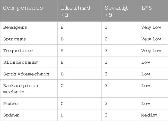
Table 2. Risk register for HAVEN.
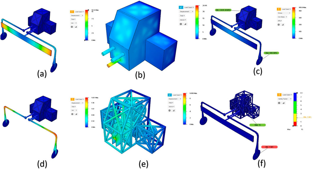
Figure 11. (a) Structural deformation – pusher, (b) Structural deformation – spinner, (c) Structural deformation - Outer cover, (d) Structural deformation - truss structure and components, (e) Safety factor of HAVEN w.r.t launch analysis and (f) Von Mises stress during launch.
3.3 Venusian atmospheric thermal stress analysis
The composition of Venus’ atmosphere is predominantly carbon dioxide, accompanied by clouds composed of sulfuric acid droplets (Hunten, 2007; Krasnopolsky and Parshev, 1981). The dense atmosphere effectively retains the Sun’s thermal energy, leading to surface temperatures exceeding 470 °C (880°F) and a pressure of around 93 bar (9.3 MPa), which is comparable to the pressure experienced at a depth of 900 m underwater on Earth (Teffeteller et al., 2022; Warren and Kite, 2023). The aforementioned circumstances were simulated using HAVEN to assess its resilience in the Venusian environment. An integrated thermal stress analysis was conducted on HAVEN, encompassing both static stress analysis and thermal analysis. It aids in comprehending the displacement within components caused by elevated pressure and temperature, as well as determining if the design incorporates a specific safety margin. Figure 12a displays the simulation outcome of the load case scenario. The spinner has a maximum movement of 12.67 mm, while the pusher shows an approximate displacement of 3 mm. Figure 12b illustrates the impact of temperature stress on the exterior cover of the mechanism box. The front side exhibits a maximum displacement of 9.294mm, while the left and right sides show an approximate displacement of 6 mm each. Figure 12c displays the outcome of the thermal stress analysis simulation conducted on the truss construction. The left and right side X-connection bars exhibit a maximum displacement of 3.393mm, while the remaining X-connection bars show a slight displacement of 1.5 mm. Figure 12d illustrates the impact of the Venusian environment on the interior covering of the mechanism box. An observed maximum displacement of 3.4 mm is present on the front side as well as the left and right sides.
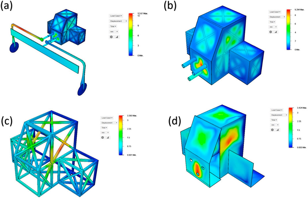
Figure 12. (a) Thermal stress analysis on HAVEN, (b) Thermal stress analysis on outer cover of mechanism box, (c) Thermal stress analysis on truss structure and (d) Thermal stress analysis on inner cover of mechanism box.
Figures 13a,b depict the simulation results of thermal stress study conducted on the gears of the mechanism box. The analysis reveals a maximum displacement of 3.65 mm on the bevel gear and spur gear located on the top side, as well as on the gear connected to the pusher on the front side. Figure 13c displays the safety factor for the HAVEN design, which has been determined by modeling in the Venusian environment. The pusher and spinner exhibit a factor of safety of 8 or greater, but certain sections of the outer cover have a factor of safety of 1, and the rest of the outer region has a factor of safety ranging from 1 to 3. The safety factor for the truss structure ranges from 3 to 6, while the inner mechanisms have a safety factor greater than 6, as depicted in Figure 13d.

Figure 13. (a) Thermal stress analysis on gears of mechanism box-1, (b) Thermal stress analysis on gears of mechanism box-2, (c) Safety factor of HAVEN w.r.t Venusian atmosphere −1 and (d) Safety factor of HAVEN w.r.t Venusian atmosphere −2.
4 Discussion
4.1 Technology readyness level
Technology Readiness Levels (TRL) are a measurement system utilized to evaluate the level of maturity of a certain technology (Olechowski et al., 2020; Olechowski et al., 2015; Mankins, 1995). Every technology project undergoes an assessment based on the criteria for each technology level, and subsequently receives a TRL grade depending on its progress. There exist nine categories of technology readiness. TRL 1 represents the minimum level of technology readiness, whereas TRL 9 signifies the maximum level of technology readiness (Smoker and Smith, 2007; Jimenez and Mavris, 2014; Yu et al., 2021). The TRL for HAVEN is currently at TRL 3. This article presents a proof-of-concept for HAVEN, which is meticulously designed and includes both analytical and experimental important features. The risk will be evaluated based on its probability (L) and magnitude (S), which might range from extremely low (green) to very high (red). The determination of whether a risk is deemed acceptable or not is made according to the risk assessment guidelines established by ECSS. Figure 14 displays the risk register for components utilized in the HAVEN system. Based on the data presented in Table 2, it can be concluded that the likelihood of a subsystem failure is quite low, however the probability of a mission failure is extremely low.

Figure 14. Risk identification guidelines.
4.2 Technical budgets
To comprehend the intricate composition and magnitude of HAVEN’s structure, the mass budget was dissected into its constituent components, as outlined in Table 3. The budget specifies a mass of 2.753kg, which includes a 5% margin. Given that this is an initial design, the mass can be minimized to meet the necessary requirements during the critical design stage by utilizing a form optimization technique.
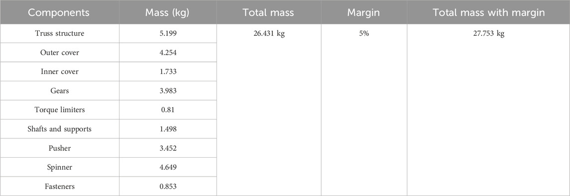
Table 3. Mass budget.
This paper employs a mass-based cost estimating relationship (CER) as a first-order approximation cost model for evaluating TRL-3 principles in the cost analysis given. Machining hours, tolerance classifications, and the development of high-temperature alloy fittings are among the manufacturing and procurement details that remain unavailable at this stage of maturity. The estimate thus provides a coefficient cost scaling rather than a definitive projection of the development cost. Despite introducing uncertainty, it is beneficial in preliminary design evaluations and the identification of significant cost contributors, such as titanium alloy manufacturing and Inconel spring production. The cost framework mechanism will be implemented as HAVEN attains TRL-4 and TRL-5 stages. This will incorporate:
1. Pricing quotations for the machining of Ti-SF61 and Ti-6Al-4V.
2. Estimations of precise assembly and metrology articulated in labor-hours, conducted rigorous high-stress/high-pressure experiments in synthetic Venusian conditions, and
3. There are overheads associated with quality assurance and systems engineering.
This data will facilitate the development of a bottom-up cost model with an associated range of uncertainty, as opposed to the current CER. The optimized model will assess the influence of technical trades involving material substitutions, tolerance relaxation, or simplified gear trains on life-cycle cost and manufacturability. The mission cost was evaluated via cost estimating relationships (CERs), which rely on historical data as documented in the NASA Cost Handbook. The initial cost for the development of HAVEN was determined using Equation 1.
Table 4 displays the itemized cost budget estimates categorized by TRL stages, taking into account material cost, manufacturing cost, AIT cost, and labor cost.
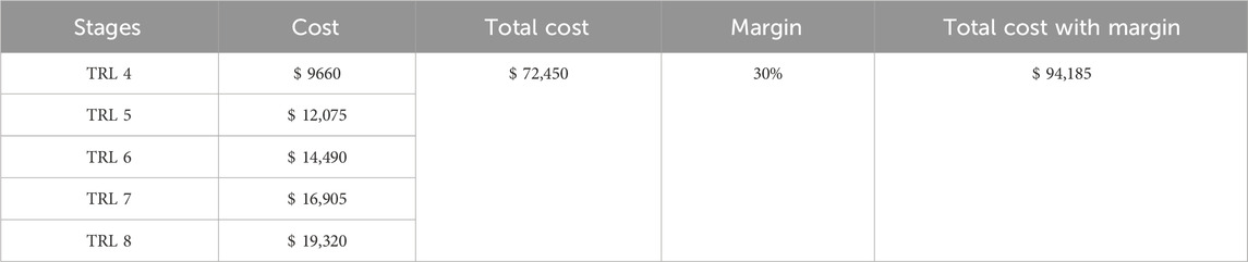
Table 4. Mass budget.
The requirements for input shaft for HAVEN (output shaft from rover) is shown in Table 5. Requirements shown in table are based on the output force require to push reverse drive pin of rover. Hence, just by varying a speed parameter, the design can achieve different output force.

Table 5. Requirement of output force for HAVEN.
Rapid actuation and the presence of barriers may induce transient stresses that were not accounted for in the quasi-static analysis. HAVEN was engineered to mitigate these effects through mechanical design: the ball-detent torque limiters facilitate automatic decoupling when transmitted torque surpasses a predetermined threshold; the compression springs in the pusher/spinner and the rack offer compliance that extends interaction time and diminishes peak forces; and the dog clutch guarantees positive engagement occurs solely upon command, thereby eliminating transients caused by slipping. These mechanisms collectively establish a sequence of sequential mechanical fuses and conditioners that limit impulse transmission to the mechanism box and the rover drive. The future scope is to enhance the current findings by: (i) developing a lumped-parameter single-degree-of-freedom model of the pusher/spinner–rack–slider train to constrain impact forces through impulse–momentum and contact-stiffness assessments; (ii) conducting explicit transient finite-element simulations of typical impact scenarios that incorporate the torque-limiter disengagement logic; and (iii) performing targeted bench tests of subassemblies utilizing instrumented hammer/pendulum impacts and heated fixtures, to ensure that recorded peak loads remain below the torque-limiter disengagement threshold and within material limits at elevated temperatures. These actions will directly influence limiter set-points, spring preloads, and clutch engagement geometry before TRL-4/5 testing.
5 Conclusion
A novel HAVEN concept has been presented, a completely mechanical system designed for hazard avoidance and vehicle navigation for AREE’s Venus rover concept. The system comprises a rack-and-pinion detection assembly and a multi-stage mechanical logic/drivetrain, including torque limiters, a dog clutch, spur and bevel gears, and a scotch-yoke, capable of functioning without electronics at around 730 K and 9.2 MPa. We established detection thresholds (rocks ≥0.35 m; slopes ≥30°), selected materials such as Ti-SF61, Ti-6Al-4V, and Inconel X-750, and provided preliminary finite element analysis under launch and Venus surface conditions. This facilitated a TRL-3 assessment with established risk, mass, and cost parameters. Subsequently, the future scope is to (i) execute Venus-analog subassembly testing to TRL-4 (thermal/pressure cycling, abrasion, high-temperature tribology), (ii) undertake transient/contact finite element analysis and endurance tests to calibrate limiter set-points and dog-clutch engagement across varying temperatures, (iii) finalize tolerance and manufacturability assessments for titanium/Inconel components and coatings, and (iv) perform integrated analog-terrain trials to measure obstacle and slope detection, false-trigger rates, and recovery sequences, followed by interface testing at the HAVEN–rover boundary. These approaches will mitigate risk, establish performance thresholds, and advance the architecture towards readiness for missions that do not require electronics in extreme environments.
Data availability statement
The original contributions presented in the study are included in the article/supplementary material, further inquiries can be directed to the corresponding author.
Author contributions
AM: Conceptualization, Data curation, Formal Analysis, Investigation, Methodology, Visualization, Writing – original draft, Writing – review and editing. BS: Conceptualization, Funding acquisition, Investigation, Project administration, Validation, Writing – original draft, Writing – review and editing. RK: Data curation, Formal Analysis, Methodology, Software, Writing – original draft, Writing – review and editing. PG: Conceptualization, Formal Analysis, Methodology, Resources, Software, Validation, Writing – original draft, Writing – review and editing. H-CW: Conceptualization, Funding acquisition, Investigation, Methodology, Project administration, Software, Supervision, Writing – original draft, Writing – review and editing.
Funding
The authors declare that financial support was received for the research and/or publication of this article. This research was supported by the National Science and Technology Council, the Republic of China, under grants NSTC 113-2221-E-194-011-MY3. This work was financially/partially supported by the Advanced Institute of Manufacturing with High-tech Innovations (AIM-HI) from the Featured Areas Research Center Program within the framework of the Higher Education Sprout Project by the Ministry of Education (MOE), and by the Research Center on Artificial Intelligence and Sustainability under the research project grant titled “Generative Digital Twin System Design for Sustainable Smart City Development in Taiwan.”
Conflict of interest
Author H-CW was employed by Hitspectra Intelligent Technology Co., Ltd.
The remaining authors declare that the research was conducted in the absence of any commercial or financial relationships that could be construed as a potential conflict of interest.
The author(s) declared that they were an editorial board member of Frontiers, at the time of submission. This had no impact on the peer review process and the final decision.
Generative AI statement
The authors declare that no Generative AI was used in the creation of this manuscript.
Any alternative text (alt text) provided alongside figures in this article has been generated by Frontiers with the support of artificial intelligence and reasonable efforts have been made to ensure accuracy, including review by the authors wherever possible. If you identify any issues, please contact us.
Publisher’s note
All claims expressed in this article are solely those of the authors and do not necessarily represent those of their affiliated organizations, or those of the publisher, the editors and the reviewers. Any product that may be evaluated in this article, or claim that may be made by its manufacturer, is not guaranteed or endorsed by the publisher.
References
Airey, M. W., Mather, T., Pyle, D., Glaze, L., Ghail, R., and Wilson, C. (2015). Explosive volcanic activity on Venus: the roles of volatile contribution, degassing, and external environment. Planet. Space Sci. 113, 33–48. doi:10.1016/j.pss.2015.01.009
Al-Hamood, A., Jamali, H. U., Abdullah, O. I., and Senatore, A. (2019). Dynamics and lubrication analyses of scotch yoke mechanism. Int. J. Interact. Des. Manuf. (IJIDeM) 13, 901–907. doi:10.1007/s12008-019-00545-y
Aljawabrah, A., and Lovas, L. (2023). Dynamic modeling of the dog clutch engagement process using hybrid automata. Jordan J. Mech. & Industrial Eng. 17 (1).
B. Alva, R. S. Bhagwat, B. Hartwell, E. Bernard, and V. Rajesh (2022). Vibrissae inspired mechanical obstacle avoidance sensor for the Venus exploration rover AREE (Reston, VA, United States: AIAA SCITECH 2022 Forum).
Arakelian, V., Le Baron, J.-P., and Mkrtchyan, M. (2016). Design of scotch yoke mechanisms with improved driving dynamics. Proc. Institution Mech. Eng. Part K J. Multi-body Dyn. 230 (4), 379–386. doi:10.1177/1464419315614431
Base, V. A. F. (2011). Falcon 9 and Falcon 9 heavy launch vehicle programs from space launch complex 4 east.
Chen, Z., and Zeng, M. (2019). Nonrelative sliding of spiral bevel gear mechanism based on active design of meshing line. Proc. Institution Mech. Eng. Part C J. Mech. Eng. Sci. 233 (3), 1055–1067. doi:10.1177/0954406218767466
Chen, Z., Ding, H., and Zeng, M. (2018). Nonrelative sliding gear mechanism based on function-oriented design of meshing line functions for parallel axes transmission. Adv. Mech. Eng. 10 (9), 168781401879632. doi:10.1177/1687814018796327
Domínguez, R., Pérez-del-Pulgar, C., Paz-Delgado, G. J., Polisano, F., Babel, J., Germa, T., et al. (2025). Cooperative robotic exploration of a planetary skylight surface and lava cave. Sci. Robotics 10 (105), eadj9699. doi:10.1126/scirobotics.adj9699
Duan, C. (2014). Analytical study of a dog clutch in automatic transmission application. SAE Int. J. Passeng. Cars-Mechanical Syst. 7 (2014-01-1775), 1155–1162. doi:10.4271/2014-01-1775
Hunten, D. M. (2007). Venus: atmosphere. Encycl. Sol. Syst. 2, 139–148. doi:10.1016/b978-012088589-3/50011-6
Jimenez, H., and Mavris, D. N. (2014). Characterization of technology integration based on technology readiness levels. J. Aircr. 51 (1), 291–302. doi:10.2514/1.c032349
Jozič, P., Zidanšek, A., and Repnik, R. (2020). Fuel conservation for launch vehicles: Falcon heavy case study. Energies 13 (3), 660. doi:10.3390/en13030660
Krasnopolsky, V., and Parshev, V. (1981). Chemical composition of the atmosphere of Venus. Nature 292 (5824), 610–613. doi:10.1038/292610a0
Lu, S.-l., Tang, H.-p., Qian, M., Hong, Q., Zeng, L.-y., and StJohn, D. (2015). A yttrium-containing high-temperature titanium alloy additively manufactured by selective electron beam melting. J. Central South Univ. 22, 2857–2863. doi:10.1007/s11771-015-2818-x
Mamiya, H., Rabajczyk, J., Watanabe, N., Kowalska, A., and Kitazawa, H. (2016). Aging-treatment-induced soft magnetism in nickel–chromium-based superalloy X-750. J. Alloys Compd. 681, 367–373. doi:10.1016/j.jallcom.2016.04.237
Mankins, J. C. (1995). Technology readiness levels. White Paper 6, 1995. Washington, DC, United States: NASA Office of Space Access and Technology.
Martinecz, C., Boesswetter, A., Fränz, M., Roussos, E., Woch, J., Krupp, N., et al. (2009). Plasma environment of Venus: comparison of Venus express ASPERA-4 measurements with 3-D hybrid simulations. J. Geophys. Res. Planets 114 (E9). doi:10.1029/2008je003174
E. R. Martinez, J. A. Santos, R. A. Miller, C. O. Johnston, and E. R. Hiss (2025). Introduction of the Venus instrumentation for thermophysics & aerosciences (VISTA) project for the NASA DA VINCI mission to Venus (3rd International Conference on Flight Vehicles, Aerothermodynamics and Re-entry). Reston, VA, United States: AIAA.
A. Mukundan, and H.-C. Wang (2023). The space logistics needs will be necessary for sustainable space activities horizon 2030 (Reston, VA, United States: AIAA).
A. Mukundan, A. Patel, K. D. Saraswat, A. Tomar, and T. Kuhn (2022). Kalam rover (Reston, VA, United States: AIAA).
A. Mukundan, A. Patel, K. D. Saraswat, A. Tomar, and H. Wang (2023a). Spriallift mechanism based drill for deep subsurface lunar exploration. AIAA AVIATION 2023 forum.
A. Mukundan, A. Patel, K. D. Saraswat, A. Tomar, and H.- Wang (2023b). Novel design of a sweeping 6-Degree of freedom lunar penetrating radar. AIAA Aviat. 2023 Forum. doi:10.2514/6.2023-4124
A. Mukundan, A. Patel, K. D. Saraswat, A. Tomar, and H.-C. Wang (2023c). “Design of a foldable laser-based energy transmission system for a mini lunar rover,” 2023 3rd international conference on electrical, computer, communications and mechatronics engineering (ICECCME) (IEEE).
Niroula, J., Xie, Q., Rajput, N. S., Darmawi-Iskandar, P. K., Rahman, S. I., Luo, S., et al. (2024). High temperature stability of regrown and alloyed ohmic contacts to AlGaN/GaN heterostructure up to 500° C. Appl. Phys. Lett. 124 (20), 202103. doi:10.1063/5.0191297
A. Olechowski, S. D. Eppinger, and N. Joglekar (2015). “Technology readiness levels at 40: a study of state-of-the-art use, challenges, and opportunities,” 2015 Portland international conference on management of engineering and technology (PICMET) (IEEE).
Olechowski, A. L., Eppinger, S. D., Joglekar, N., and Tomaschek, K. (2020). Technology readiness levels: shortcomings and improvement opportunities. Syst. Eng. 23 (4), 395–408. doi:10.1002/sys.21533
Pederson, R. (2002). Microstructure and phase transformation of Ti-6Al-4V: luleå tekniska universitet.
Pradhan, D. K., Moore, D. C., Kim, G., He, Y., Musavigharavi, P., Kim, K.-H., et al. (2024). A scalable ferroelectric non-volatile memory operating at 600°C. Nat. Electron. 7 (5), 348–355. doi:10.1038/s41928-024-01148-6
Raut, N., Yakkundi, V., Sunnapwar, V., Medhi, T., and Jain, V. K. S. (2022). A specific analytical study of friction stir welded Ti-6Al-4V grade 5 alloy: stir zone microstructure and mechanical properties. J. Manuf. Process. 76, 611–623. doi:10.1016/j.jmapro.2022.02.036
Sauder, J., Hilgemann, E., Kawata, J., Stack, K., Parness, A., and Johnson, M. (2017a). Automation rover for extreme environments (AREE). NASA TV, Pasadena, CA, United States: NASA Jet Propulsion Lab.
Sauder, J., Hilgemann, E., Johnson, M., Parness, A., Hall, J., Kawata, J., et al. (2017b). Automation rover for extreme environments.
Sawyer, W. G., Diaz, K. I., Hamilton, a, Matthew, A., and Micklos, B. (2003). Evaluation of a model for the evolution of wear in a scotch-yoke mechanism. J. Trib. 125 (3), 678–681. doi:10.1115/1.1537271
Seiff, A., Schofield, J., Kliore, A., Taylor, F., Limaye, S., Revercomb, H., et al. (1985). Models of the structure of the atmosphere of Venus from the surface to 100 kilometers altitude. Adv. Space Res. 5 (11), 3–58. doi:10.1016/0273-1177(85)90197-8
Shiotsu, I., Tani, H., Kimura, M., Nozawa, Y., Honda, A., Tabuchi, M., et al. (2019). Development of high efficiency dog clutch with one-way mechanism for stepped automatic transmissions. Int. J. Automot. Eng. 10 (2), 156–161. doi:10.20485/jsaeijae.10.2_156
Smoker, R. E., and Smith, S. (2007). System cost growth associated with technology-readiness level. J. Parametrics 26 (1), 8–38. doi:10.1080/10157891.2007.10462276
Taylor, F. W., Svedhem, H., and Head, J. W. (2018). Venus: the atmosphere, climate, surface, interior and near-space environment of an Earth-like planet. Space Sci. Rev. 214, 35–36. doi:10.1007/s11214-018-0467-8
Teffeteller, H., Filiberto, J., McCanta, M., Treiman, A., Keller, L., Cherniak, D., et al. (2022). An experimental study of the alteration of basalt on the surface of Venus. Icarus 384, 115085. doi:10.1016/j.icarus.2022.115085
Wang, Y., Pan, Q., Song, Y., Li, C., and Li, Z. (2013). Hot deformation and processing maps of X-750 nickel-based superalloy. Mater. & Des. 51, 154–160. doi:10.1016/j.matdes.2013.03.081
Warren, A. O., and Kite, E. S. (2023). Narrow range of early habitable Venus scenarios permitted by modeling of oxygen loss and radiogenic argon degassing. Proc. Natl. Acad. Sci. 120 (11), e2209751120. doi:10.1073/pnas.2209751120
Keywords: automaton rover, obstacle avoidance, scotch-yoke mechanism, technology readiness level, HAVEN
Citation: Mukundan A, Shastri B, Karmakar R, Gade PC and Wang H-C (2025) HAVEN: a hazard avoidance and VEhicular navigation system for autonomous maneuvering in the AREE venus rover. Front. Mech. Eng. 11:1707818. doi: 10.3389/fmech.2025.1707818
Received: 18 September 2025; Accepted: 10 November 2025;
Published: 03 December 2025.
Edited by:
Chengxi Zhang, Jiangnan University, ChinaReviewed by:
Jian Ding, University of Surrey, United KingdomHima Bindu Valiveti, Gokaraju Rangaraju Institute of Engineering and Technology (GRIET), India
Hua Fei, Jiangnan University, China
Copyright © 2025 Mukundan, Shastri, Karmakar, Gade and Wang. This is an open-access article distributed under the terms of the Creative Commons Attribution License (CC BY). The use, distribution or reproduction in other forums is permitted, provided the original author(s) and the copyright owner(s) are credited and that the original publication in this journal is cited, in accordance with accepted academic practice. No use, distribution or reproduction is permitted which does not comply with these terms.
*Correspondence: Hsiang-Chen Wang, aGN3YW5nQGNjdS5lZHUudHc=
†These authors have contributed equally to this work