 Hiren Shah
 Gaurangkumar Chaudhari
 Vijay Dhiman3
 Ravi Bhatt
 Sachin Salunkhe
 Lenka Cepova
- 1Sarvajanik College of Engineering & Technology, Sarvajanik University, Surat, India
- 2C. K. Pithawala College of Engineering & Technology, Surat, Gujarat, India
- 3Government Engineering College, Valsad, India
- 4Vidhyadeep Institute of Engineering and Technology, Vidhaydeep University, Surat, Guajrat, India
- 5Department of Biosciences, Saveetha School of Engineering, Saveetha Institute of Medical and Technical Sciences, Chennai, India
- 6Faculty of Engineering, Department of Mechanical Engineering, Gazi University, Ankara, Türkiye
- 7Department of Machining, Assembly and Engineering Metrology, Faculty of Mechanical Engineering, VSB-Technical University of Ostrava, Ostrava, Czechia
The Pelton turbine is the most effective impulse turbine and has excellent operational performance in high water heads as well as low water rates. The bucket splitter design plays a crucial role, as its design is responsible for its efficiency. The water jet strikes the bucket splitter and produces the forces that move the turbine runner to generate mechanical energy from the kinetic head. A comparative analysis of seven differently designed Pelton turbine buckets is done in this paper. Finite Element Analysis (FEA), as a constructive method to check the static structural analysis in the Pelton turbine bucket, has been used to compare the performance. The effect of changing various parameters like bucket exit angle, bucket width, and bucket thickness on the life of the bucket is discussed here. This study aims to compare and achieve the best design of the Pelton bucket to improve its strength by reducing von mises stress and reducing the deformation. Bucket width is achieved as 110 mm, thickness 5 mm, splitter tip level, and cutout length both at 3 mm, and cutout width at 23.25 mm for effective flow over the bucket surface. The bucket exit angle at the middle section is achieved as 15° to reduce the von mises stress and deformation significantly.
Introduction
An essential tool for engineers, Autodesk Inventor shines in 3D modelling and simulation. It is beneficial in the development of the Pelton turbine, as it helps create seven different identical designs of Pelton buckets. Its sophisticated capabilities and easy-to-use interface allow researchers to visualise and optimise complex bucket geometries with precision in both form and function. For this reason, the Pelton turbine buckets are modelled using Autodesk Inventor. On the other hand, ANSYS is an expert in Finite Element Analysis (FEA), which is essential for determining structural integrity. With ANSYS 16.2, each of the seven designs in the Pelton turbine development is subjected to a thorough Finite Element Analysis (FEA). During the procedure, variables such as von Mises stress and total deformation can be examined, yielding valuable insights into the structural functionality of Pelton bucket designs. This comprehensive analysis assists researchers in optimising design parameters and ensuring Pelton turbine buckets meet standards, enhancing reliability. The Pelton buckets are fundamentally two ellipsoidal cup-shaped buckets joined together. A sharp edge between the two buckets, called the splitter, bifurcates the approaching jet and spreads it over each bucket, allowing the water to leave smoothly from the edges. There is a cutout at the outer end of the bucket that permits the jet to strike the splitter directly on the subsequent bucket, ensuring a relatively effortless flow and consistent torque generation. The geometry of the bucket is primarily governed by factors such as splitter angle, height, the shape of the cutout, depth, width, and exit angle (Perrig, 2007).
Recent studies have focused on refining the predictive capability of computational models for Pelton turbine performance. Zhao et al. evaluated advanced modeling frameworks to enhance the accuracy of energy performance prediction and provided valuable guidance for hydroelectric applications (Zhao et al., 2025). Similarly, Wu et al. analyzed flow asymmetry within symmetric inlet loop pipe–nozzle systems and identified its impact on uneven power generation in Pelton turbines (Wu et al., 2025). These studies highlight the importance of improving numerical modeling accuracy and flow uniformity, which aligns with the present work’s objective to enhance bucket geometry for improved stress distribution and deformation control. In the present study, the jet bucket interaction is considered under a steady impingement condition, where the jet alignment with the bucket remains fixed. This assumption provides a controlled basis for examining the influence of geometric variations on flow distribution and energy transfer. In practical operation, however, minor phase shifts between the jet and bucket may occur due to changes in load, nozzle regulation, or transient effects. These operational variations, while significant for large scale dynamic studies, are beyond the current scope and will be considered in future analyses. Furthermore, the study presents seven distinct conceptual models of Pelton turbine buckets, designed with different geometric features, and includes their evaluation through static structural finite element analysis to determine the optimal bucket configuration. The present analysis is performed under steady static pressure loading conditions, without accounting for dynamic load fluctuations or fatigue effects that occur during actual turbine operation. Therefore, the results primarily represent the structural response of the bucket under steady loading and are intended for preliminary geometric evaluation and comparative screening rather than comprehensive lifetime or fatigue assessment.
Design parameters
Lester Pelton developed the design of the Pelton turbine in 1880 (Pelton, 1880). Researchers have focused on the analysis or design optimisation of a distributor, injector, and bucket erosion (Alnakhlani et al., 2014). However, there is a scope for research to analyse the geometrical aspects of modelling the Pelton bucket. Normally, there is a tendency to select a bucket design that is used by industries. It simply neglects its geometrical importance and its effect over time. However, there is stress distribution and deformation associated with the bucket splitter tip and the inner surface of the bucket. Therefore, a proper understanding of each geometrical element is necessary to minimise the von mises stresses and deformation. The key challenges relating to the design of the Pelton bucket are enhanced in Figure 1 (Bhattarai et al., 2019).

Figure 1. Challenges for Pelton bucket analysis (Bhattarai et al., 2019).
The present study focuses on von Mises stresses and total deformation at the bucket splitter tip and inner surfaces by varying various bucket parameters. Lancaster University has the necessary facilities to modify and optimise the new shape of the Pelton bucket (Waterpower Laboratory). The Pelton bucket was further improved analytically by modifying the geometry of the cutout, the splitter tip, and the outer side of the bucket regions. Computational fluid dynamics (CFD) was used to evaluate the effect of these modifications.
The structural analysis of the Pelton bucket was performed under realistic hydraulic operating conditions corresponding to a laboratory scale Pelton turbine. The turbine operates at a net head of 45 m with a single jet diameter of 0.02 m, delivering a discharge of 0.015 m3/s (900 LPM). The resulting jet velocity of approximately 30 m/s impinges on a runner of 0.33 m diameter, rotating at 1,000 rpm, with a pitch circle diameter (PCD) of 0.255 m and equipped with 18 buckets. The jet to runner diameter ratio (jet ratio ≈ 0.99) and overall power output of 3.75 kW satisfy the standard design criteria for Pelton turbine operation. These hydraulic inputs were used to ensure that the geometric parameter variations studied through FEA represent practical working conditions of a Pelton bucket.
The bucket geometry notations serve as a crucial tool for justifying and comparing various models of the Pelton turbine bucket. This notation is further represented in Figure 2. When designing a new Pelton bucket, factors such as cutout width, cutout length, splitter tip height, exit angle, and bucket thickness significantly influence stress generation. These geometric parameters were selected based on established design guidelines and validated literature, supported by prior CFD based parametric optimization studies such as Zidonis et al. (2015). Their findings demonstrated that variations in these parameters strongly affect the hydraulic efficiency and structural loading of Pelton buckets. Accordingly, the chosen dimensions in this study represent a balanced configuration derived from literature recommendations and iterative design refinement to ensure realistic and reproducible results. Employing Finite Element Analysis (FEA) becomes pivotal for assessing stress concentration and deformation across different zones of the Pelton bucket. This study explores seven distinct Pelton bucket designs (PBD). Table 1 provides detailed dimensions of all PBDs. The conceptual models are formulated based on these dimensions to guide the design process.
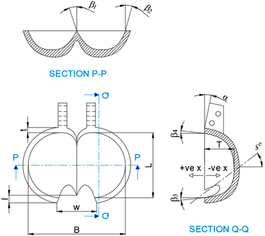
Figure 2. Bucket geometry notation (Shah et al., 2021).

Table 1. Dimensions of PBD.
Conceptual models
In hydraulic turbine systems, the Pelton bucket’s performance and efficiency are significantly impacted by its geometric configuration. This configuration is a core technical element of its design. Energy conversion and flow dynamics within the turbine assembly can be optimally achieved by adjusting parameters such as bucket shape, curvature, and size. The following points are considered to create bucket models.
• Radial (normal to pitch circle diameter of the runner) middle section profile of the half bucket is based on the elliptical design (Zidonis et al., 2015).
• The tangential section (tangent to the pitch circle diameter of the runner) of the bucket is modelled using B-spline curves in Autodesk Inventor software.
• The transverse sections are made of different profiles according to the design criteria as mentioned in Table 1.
• The bucket’s inner surface is generated by taking different sections along the depth of the bucket, and a smooth surface is created by lofting them together.
The geometric variations among seven different models of Pelton Bucket Designs (PBD) can be readily understood by referring to Figure 3 through Figure 9. The images presented below include the different views of PBD (section P-P), as described in Figure 2. A discussion of parametric variables and how they affect the seven distinct PBDs is covered in the following images and paragraphs. PBD 1 is based on a widely accepted method by industries in practice introduced by Thake (2000). The elliptical cross-section on two axes, as shown in Figure 3, is generally a good choice for mega power plants. The design is lightweight, and the cutout is optimized. The bucket tip is lowered and the inclination angle is increased to 20° for the reduction of back pressure losses during the first jet interaction. PBD 1 has a lower thickness and is ultimately cost-effective. However, the deep sections of the bucket need more strength as they carry more forces as compared to other regions.

Figure 3. Different views of Pelton bucket Design 1 (PBD1). (a) Front view. (b) Side view. (c) Rear view. (d) Section view.
It is not easy to handle higher water impingement with PBD 1. So, an elliptical reinforcement rib of cross-section 1.75 × 3.5 mm is provided at the backside of the bucket along the deepest line of the bucket profile, as shown in PBD 2 of Figure 4. The improved smooth inner surface may give fine results for a streamline of water particles. It can also be improved by increasing the surface contact area of the inner surface. The highlight of the evolution of bucket design is indicated in Figure 4.

Figure 4. Different views of Pelton bucket Design 2 (PBD2). (a) Front view. (b) Side view. (c) Rear view. (d) Section view.
It is a challenging task to achieve the smooth flow characteristics with PBD 1 and PBD 2. The bucket’s inner surface is of major concern to designers, as smooth power transmission is required from the jet to the bucket. An abrupt change in the water path while passing through the inner surface increases losses and pressure concentration at that section. It greatly reduces the efficiency and erodes the bucket more rapidly. As shown in Figure 5, PBD 3 is designed with a zero splitter tip level and increased bucket thickness by 1 mm. It has a rectangular shape with a rounded corner bucket model to achieve a smooth flow pattern. It has improved the inner surface, allowing water to flow smoothly without sudden changes in direction. The edge line angles on the bucket will affect the distribution of forces in different sections of the bucket’s inner surface. To get the proper flow bifurcation, the splitter tip level should be increased with respect to the outer edge of the bucket. The bucket cutout length and width need to be optimised to reduce the deformation at the splitter tip area. It is clear that those four parameters: bucket thickness, splitter tip level, cutout width, and length will play a vital role in the smooth flow of water particles. It will reduce the deformation also.
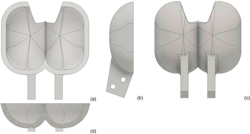
Figure 5. Different views of Pelton bucket Design 3 (PBD3). (a) Front view. (b) Side view. (c) Rear view. (d) Section view.
PBD 4 is modified from PBD 3 to have a constant edge line angle transition, as shown in Figure 6. Uniform distribution of von Mises stresses is a concern to adopt this design in the industry. This type of Pelton bucket, known as the traditional Pelton bucket, is commonly used in industries. In Figure 7 from PBD 5, variable thickness, along with the depth of the bucket from 5 mm at the top to 8 mm at the bottom, is used to improve the strength, and the width of the bucket is increased to achieve a smoother transition over the surface. The backpressure effect can suppress the performance of the hydro system, particularly with the given design.
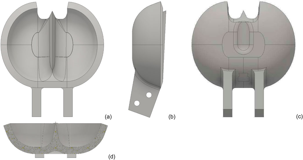
Figure 6. Different views of Pelton bucket Design 4 (PBD4). (a) Front view. (b) Side view. (c) Rear view. (d) Section view.
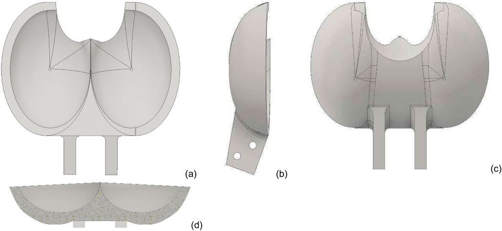
Figure 7. Different views of Pelton bucket Design 5 (PBD5). (a) Front view. (b) Side view. (c) Rear view. (d) Section view.
Another type of turbine, shown in Figure 8, has two parallel plates across the bucket runner assembly. It is often called a hooped Pelton turbine. This design aims to transform the cantilever structural system into a supported, uniformly distributed Pelton Runner. While stress concentration can be substantially reduced, the system’s weight increases significantly. This elevated weight may contribute to an augmented dead load on the system, ultimately affecting the hydraulic performance of the Pelton turbine.

Figure 8. Different views of Pelton bucket Design 6 (PBD6). (a) Front view. (b) Side view. (c) Rear view. (d) Section view.
The deeper and wider sections of the PBD7 (Figure 9) are reinforced. This reinforcement is necessary because these areas bear higher forces compared to others. The extremely smooth edge angle transition at the outlet and the inner surface’s smoothness contribute to a streamlined flow inside the bucket, enabling efficient utilisation of the water’s kinetic energy. The reduced cutout width and cutout length in comparison to PBD 5 further aid in minimizing the unused kinetic energy of the jet.

Figure 9. Different views of Pelton bucket Design 7 (PBD7). (a) Front view. (b) Side view. (c) Rear view. (d) Section view.
Understanding and identifying the limitations of each design can be a challenging task. However, with the assistance of Figure 10, one can easily comprehend all seven PBDs and their respective geometrical changes. The names, along with their corresponding geometry and shape, are discussed in the same figure. Briefly, the evaluation of the Pelton bucket design can be understood through Figure 10.
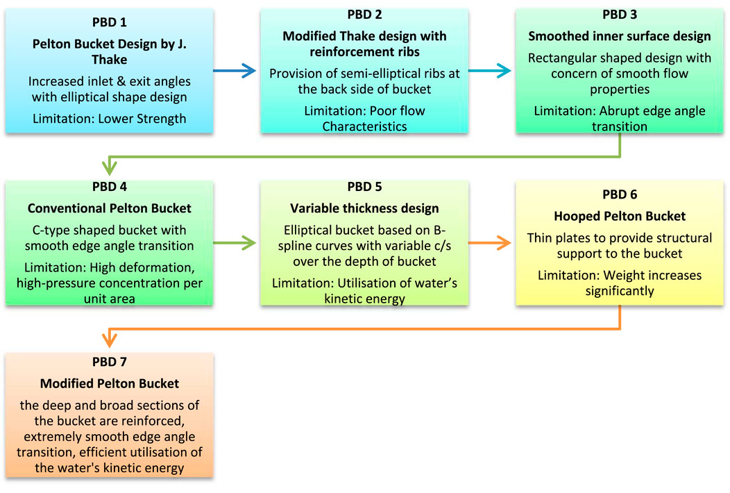
Figure 10. Evaluation of Pelton bucket Design (Shah, 2024).
Numerical analysis
The present numerical investigation follows a similar approach to the recent study by Zhao et al., who analyzed the influence of bucket flow patterns on energy conversion characteristics in Pelton turbines (Zhao et al., 2023). Their results emphasize how local flow structures within the bucket directly affect turbine efficiency, supporting the rationale behind the geometric parameter modifications considered in this study. The computer aided Pelton turbine bucket models are prepared in Autodesk Inventor software (Autodesk Inc, 2016). An effective numerical method for simulating and analysing intricate structures, such as the Pelton turbine bucket, is called finite element analysis (FEA). The optimization process was conducted using an iterative FEA based parametric optimization approach rather than an explicit mathematical algorithm. In the present work, geometric optimization was carried out without relying on advanced automated techniques such as genetic algorithms, neural network driven design searches, surrogate models, or other multi objective evolutionary tools. Instead, a straightforward parametric strategy was employed. The principal geometric attributes of the bucket including width, thickness, exit angle, splitter-tip elevation, and cutout proportions were adjusted step by step within realistic engineering limits. Each variation was examined through repeated FEA simulations under identical loading and constraints. The bucket configuration offering the lowest von Misses stress together with the least deformation was considered the most suitable. This method provides a practical compromise between computational demand, design accuracy, and manufacturability, and is therefore appropriate for early stage refinement of Pelton bucket geometries in both research and laboratory scale applications.
It entails breaking down a real world object or system into discrete, networked parts that are connected by nodes to approximate continuous activity. FEA makes it possible to forecast how Pelton bucket structures will react to stress and deformation by using mathematical models for these components. Before actual prototypes are constructed, the FEA technique is used to evaluate the robustness and endurance of designs, identify potential weaknesses, and optimise structure. Material properties are taken from the standard ANSYS library for structural steel (Ansys Inc, 2015). Using FEA, the structural responses of Pelton Buckets to external forces may be comprehensively investigated. The optimization relied on comparative evaluation of stress and deformation outcomes from successive simulation runs to identify the most structurally efficient configuration. This deterministic parametric optimization approach is widely adopted in structural design problems where response variables depend directly on geometric parameters and loading conditions (Zidonis et al., 2015; Zidonis and Aggidis, 2016). The following parameters and settings are considered for finite element analysis of seven Pelton turbine bucket models.
• Tetrahedral elements are used to ensure a high quality, smooth transition (Thake, 2000; Lorentz, 2012a).
• To ensure an effective mesh, the element size in Figure 11 is maintained at a constant 2 mm (Thake, 2000; Lorentz, 2012a).
• Figures 12, 13 give constraints given to Pelton buckets.
• There are defined pressure based loading conditions for all Pelton buckets. Figure 12 shows an average pressure of 0.15 MPa at 100% nozzle opening (Chaudhari, 2016).
• A fixture is provided at the fastening holes, as shown in Figure 13.
• The number of iterations is set to automatic. The program controlled iterations are originally set to 1 million till convergence.
• The rotation of the turbine is neglected. Only the Pelton bucket is being considered.

Figure 11. Mesh model.

Figure 12. Constrained given to Pelton bucket - average pressure distribution.

Figure 13. Constrain given to Pelton bucket - fixed support.
In this investigation, a full CFD derived flow field distribution was not generated; instead, the loading on the bucket surface was applied as a steady and uniform pressure. This simplified representation is commonly used in structural assessments of Pelton buckets when the focus is on comparing different geometric configurations rather than resolving transient flow details (Perrig, 2007; Thake, 2000; Chaudhari, 2016). Earlier studies have shown that the main stress zones particularly around the splitter tip, the cutout, and the inner curved surfaces are largely dictated by the pressure spike that arises when the jet initially strikes and divides at the splitter (Dudley, 1992; Sánchez-Sanz et al., 2021). More detailed CFD research has further demonstrated that phenomena such as jet fragmentation, free-surface deformation, and internal recirculation can alter the pressure distribution and, in turn, the structural response of the bucket (Wu et al., 2025; Zidonis et al., 2015). Accurately capturing these effects requires a tightly coupled CFD FEA framework, which lies outside the scope of the present static structural analysis. A comprehensive coupled flow structure study is planned for future work to more fully characterize these interactions in Pelton turbine buckets.
Mesh independence and quality study
To verify the numerical stability of the finite element results, a comprehensive mesh independence and mesh quality assessment was carried out using the representative bucket model (PBD4). Four different mesh densities were examined coarse (4.0 mm), medium (3.0 mm), fine (2.0 mm), and very fine (1.5 mm). Comparable mesh refinement studies have been reported in Pelton bucket and hydraulic turbine research by Perrig (2007), Chaudhari (2016), and Zidonis and Aggidis (2016).
The corresponding variations in peak von Mises stress, deformation, computational effort, and mesh quality indicators are summarized in Table 2. Reducing the element size from 4.0 mm to 3.0 mm noticeably improved the accuracy of the stress field; however, further refinement beyond the 2.0 mm mesh resulted in only minor changes, typically within about 1.5%. This behaviour indicates that the solution becomes mesh independent at 2.0 mm while still keeping the computational demand at a practical level an outcome that aligns with recommendations found in previous turbine-structure analyses (Barragan et al., 2025; Lorentz, 2012b).
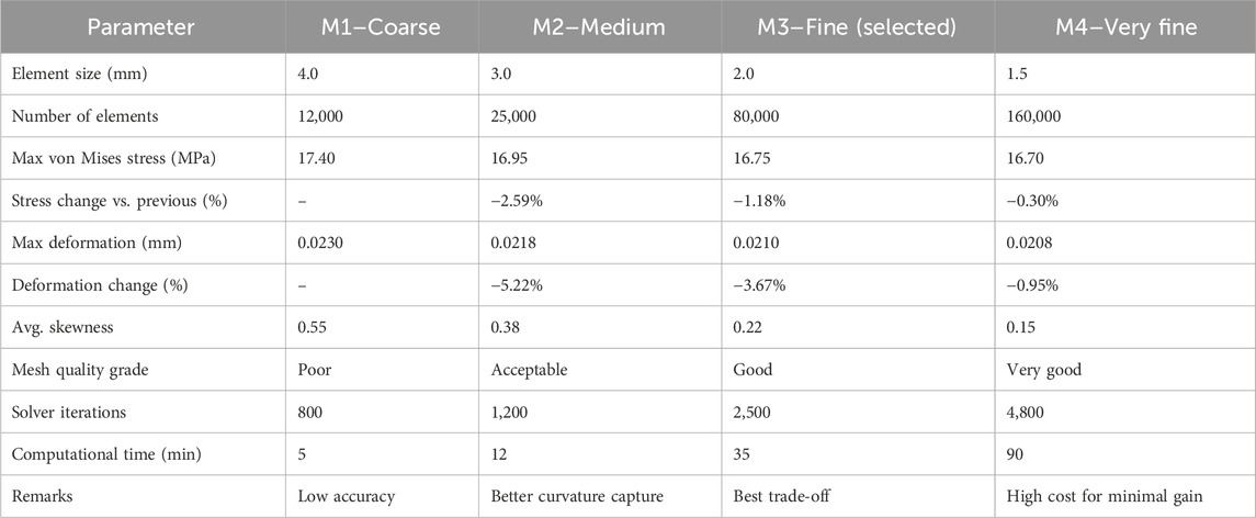
Table 2. Mesh independence and mesh quality results.
The choice of a 2.0 mm element size for all finite element simulations was made after examining numerical accuracy, mesh quality, and overall computational effort. As highlighted in the mesh-independence results (Table 2), refining the element size from 4.0 mm to 2.0 mm notably improved the stress and deformation predictions. Beyond this level, however, the benefits became negligible moving to a 1.5 mm mesh changed the maximum von Mises stress by only 0.30% and the deformation by just 0.95%. This plateau in improvement indicates that the solution has essentially reached mesh independence at 2.0 mm, a trend also observed in earlier Pelton bucket and runner studies by Perrig (2007), Lorentz (2012b), and Zidonis and Aggidis (2016).
The computational cost further supports this choice. While the 2.0 mm mesh required roughly 35 min per simulation, the very fine 1.5 mm mesh nearly tripled the time to around 90 min, a typical pattern in FEA of curved hydraulic components where refinements rapidly escalate the computational load (Barragan et al., 2025). Given that the study evaluates seven different bucket geometries, using a finer mesh would have made the analysis unnecessarily time consuming without adding meaningful accuracy. The 2.0 mm mesh also obtained a favourable skewness value of about 0.22, indicating that element distortion was low and that the stress distribution, especially around sensitive regions such as the splitter tip and cutout, remained stable. For these reasons, the 2.0 mm element size offers the best compromise between precision, numerical robustness, and computational practicality, in line with recommendations from previous turbine modelling literature.
The convergence characteristics are further illustrated in Figure 14, which plots the maximum von Mises stress against element size. The curve shows a clear stabilization of the results once the mesh is refined to 2.0 mm, with only slight changes thereafter. Such monotonic behaviour closely matches validated results in earlier FEA investigations by Perrig (2007) and Chaudhari (2016), confirming the reliability of the numerical model used in this study.
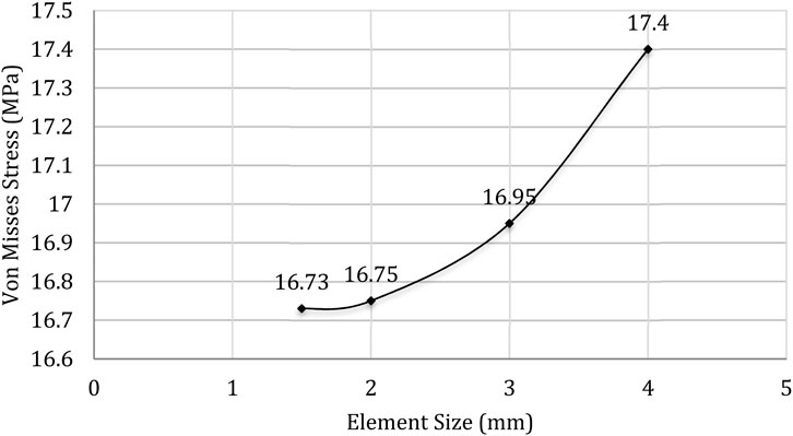
Figure 14. No. mesh convergence plot–max von Mises stress vs. element size.
Model description and validation
Validation of the numerical model was carried out through a combination of mesh convergence checks, comparison with established literature, and examination of the physical plausibility of the FEA response. The mesh independence study showed that both stress and deformation values level off at an element size of 2.0 mm, indicating that the results are no longer sensitive to further refinement. The distribution of stresses most notably the elevated concentrations at the splitter tip, the cutout boundary, and the bucket root closely mirrors the behaviour documented in earlier validated Pelton bucket investigations by Perrig (2007), Zidonis et al. (2015), and Chaudhari (2016). Likewise, the deformation magnitudes obtained in this study (approximately 0.020–0.023 mm) fall within the range reported for Pelton components subjected to comparable hydraulic loading conditions (Lorentz, 2012b). Collectively, these observations confirm that the finite element model used here provides a reliable and stable basis for comparing the structural performance of the seven bucket geometries.
Results and analysis
Figure 15 shows the Finite Element analysis of PBD 1. Stress concentration is observed at the splitter, cutout, and fixture sections due to a reduced bearing area and low material thickness in these areas. The uneven distribution of load over the surface is a result of an abrupt contour change in the flow path, leading to deformation. The maximum deformation observed is 0.0014 mm at the splitter tip and cutout section. The cutout section displays the highest stress concentration, reaching a value of 22.40 MPa, due to its reduced thickness in this region.
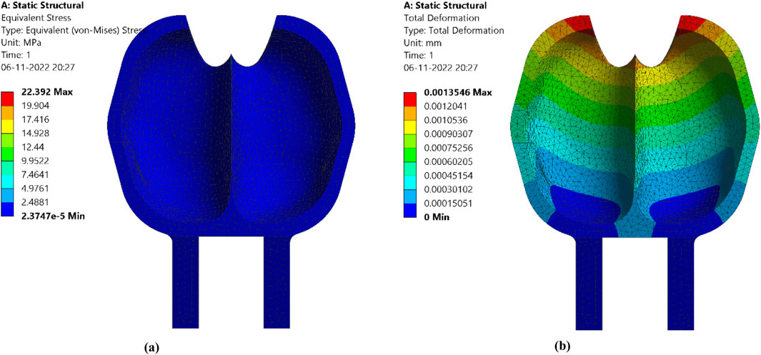
Figure 15. FEA of Pelton bucket Design 1. (a) Von Mises stress. (b) Total deformation.
In the Finite Element analysis of PBD2, stresses are reduced through reinforced structures in curvature areas, as demonstrated in Figure 16. This reinforcement enhances the overall strength of the structure, leading to a visible reduction in stresses. The deformation is significantly decreased. The maximum deformation occurs at the splitter tip and cutout section, measuring 0.0005 mm at the cutout section. Von Mises stresses are reduced to 19.76 MPa, reflecting an 11.74% decrease compared to PBD1. Notably, major stresses are concentrated at the cutout section. This suggests that modifications to the cutout design could further reduce stress concentrations in this area.
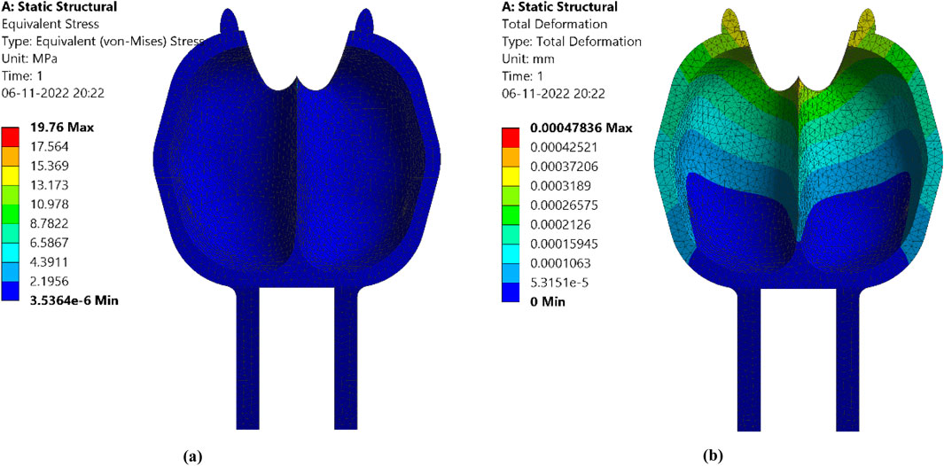
Figure 16. FEA of Pelton bucket Design 2. (a) Von Mises stress. (b) Total deformation.
The Finite Element analysis of the rectangular-shaped Pelton bucket (PBD3) is shown in Figure 17. This shape significantly enhances the strength of the bucket. To reduce deformation, both the cutout length and cutout width are increased; however, a slight increase in deformation is observed at the splitter tip and cutout section due to higher thickness. Von Mises stresses are reduced by 10.37%, reaching a value of 17.71 MPa.

Figure 17. FEA of Pelton bucket Design 3. (a) Von MISES stress. (b) Total deformation.
The Finite Element analysis of the C shaped design (PBD 4) is presented in Figure 18. Stress concentration is observed at the fixture boundaries. To evenly distribute stresses, the cutout length and cutout width are decreased to 7.5 mm and 30 mm, respectively. However, total deformation rises at the splitter tip due to the concentration of high pressure per unit area. Notably, the deformation is significantly increased to 0.0210 mm at the splitter tip area compared to PBD 3. In response to this, the height of the splitter tip is raised to 3 mm. Von Mises stresses are concentrated to 5.42% under a load of 16.75 MPa. The distribution of stresses is more uniform compared to the previously discussed Pelton turbine bucket designs. Stress distribution at the inner surface is improved within the range of 1.8 MPa–16.75 MPa due to the increased splitter tip level. Industries recommend this design for its performance.

Figure 18. FEA of Pelton bucket Design 4. (a) Von Mises stress. (b) Total deformation.
PBD 5 shows a significant cutout section in the Pelton turbine bucket. As shown in Figure 19, stresses are reduced to a minimum due to the variable thickness design. A significant 96.62% reduction in deformation is also attributed to the large splitter bearing area at the tip. To effectively utilise the kinetic energy of water, the cutout width and cutout length are increased to 24.5 mm and 47 mm, respectively. Von Mises stresses are notably reduced at the splitter tip area due to the round cutout shape, reaching a reduction of 73.85% with a value of 4.38 MPa.

Figure 19. FEA of Pelton bucket Design 5. (a) Von Mises stress. (b) Total deformation.
Figure 20 represents the Finite Element analysis of the hooped Pelton turbine bucket. It is expected that stress concentration and deformation will significantly reduce due to the support of two parallel plates. For the present analysis, the data were derived from the doctoral research of Chaudhari (2016). Von Mises stresses are reduced to 5.39 MPa, reflecting a 67.83% decrease compared to the conventional Pelton bucket design 4.

Figure 20. FEA of Pelton bucket Design 6. (a) von Mises stress. (b) Total deformation (Chaudhari, 2016).
After comparing six designs of the Pelton bucket, it was decided to reduce the cutout height of PBD 5. The increased cutout section inefficiently converts the kinetic energy of water into the rotation of the Pelton turbine. Additionally, in relation to PBD 6, to achieve a balance between weight reduction and sufficient strength, ribs have been added throughout the backside of the bucket, as shown in Figure 21. It is called a modified Pelton turbine bucket. The increased splitter tip contributes to a remarkable reduction in total deformation at the splitter tip. Pressure is distributed more uniformly inside the bucket compared to other designs. Von Mises stresses are notably reduced at the inner surface, ranging from 0.39 MPa to 3.56 MPa. The maximum deformation occurs at the cutout section, measuring 0.0035 mm. Von Mises stresses are reduced to 3.56 MPa, reflecting a 78.75% decrease compared to the conventional Pelton bucket design 4.
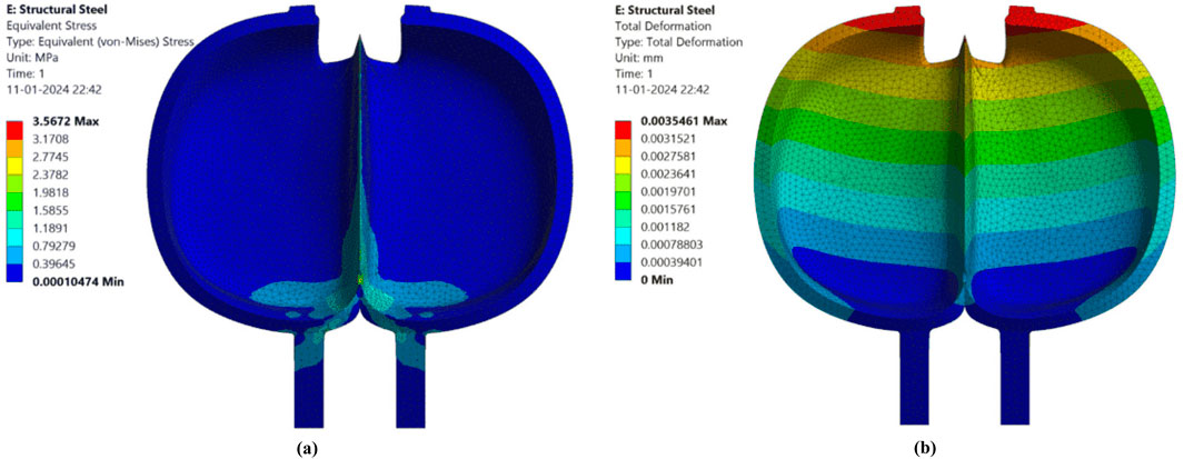
Figure 21. FEA of Pelton bucket Design 7. (a) Von mises stress. (b) Total deformation.
Referencing Table 3 enables a detailed examination of the finite element analysis (FEA) results, including von-Mises stress, across the seven distinct Pelton bucket designs. A comparison between PBD7 and the remaining PBDs (PBD1 to PBD6) is presented. The maximum reduction in von Mises stress, compared to PBD1, is 84.1%, which corresponds to the conceptual design proposed by Thake (2000). The minimum reduction in von Mises stress, at 18.72%, is observed in relation to PBD5, attributed to its larger cutout section. The von Mises stress is reduced to 78.74% in the modified Pelton bucket (PBD7) compared to the traditional Pelton bucket design (PBD4). Additionally, the von Mises stress is decreased by 33.95% in the modified Pelton bucket (PBD7) compared to the hooped Pelton bucket design. Although the present evaluation primarily concentrates on structural stress reduction, it is acknowledged that the geometric modifications introduced across the proposed bucket designs may also influence hydraulic performance. Improvements such as smoother edge angle transitions, optimized splitter geometry, and reinforced bucket sections are expected to promote better jet guidance, minimize flow separation, and enhance the utilisation of the jet’s kinetic energy. Similar observations were reported by Enhancing Hydraulic Efficiency of Pelton Turbines through Bucket Geometry Optimisation, where optimisation of parameters such as exit angle, bucket width, and length resulted in an efficiency improvement of approximately 2.5% (Dudley, 1992). Accordingly, the final Modified Pelton Bucket (PBD 7) is anticipated to provide not only improved structural integrity but also qualitative gains in flow smoothness and overall hydraulic efficiency.

Table 3. Results of FEA.
Actual Pelton turbine
Following the finite element analysis of seven conceptual Pelton turbine bucket models, the seventh design (PBD7) was identified as the most efficient and structurally superior configuration. This outcome guided the decision to proceed with the manufacturing of PBD7 for experimentation. The bucket was produced using a carefully controlled sand casting process, resulting in high dimensional accuracy and surface integrity. Red brass (C23000) was selected as the bucket material to facilitate reliable performance and simplify large-scale production, whereas the runner was fabricated from mild steel (EN8) (Chaudhari, 2016; ASMEB16.51-2013, 2018; Gopalkrishna et al., 2019). The obtained results clearly emphasize the enhanced performance of the modified bucket compared to the other six designs. To support this, Figure 22 depicts the assembly of the modified buckets with the runner plate, offering a complete view of the integration. Additionally, Figure 23 combines two dimensional engineering drawings (front, top, and side views) with actual photographs of the runner, providing both technical and practical insight into the final manufactured turbine. These results demonstrate the successful transition from analysis to fabrication, highlighting the effectiveness of the modified design for experimental applications. In the optimized PBD7 design, localized reinforcement has been incorporated at the bucket root and adjoining fillet regions to alleviate stress concentration and enhance structural stiffness under operational loading. This modification ensures improved durability while maintaining the manufacturability of the design.
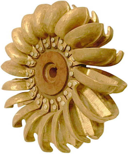
Figure 22. Modified Pelton turbine bucket runner assembly.

Figure 23. Modified Pelton runnerexpe. (a) 2D Drawing of bucket. (b) Actual image of runner.
In the present study, an 18 bucket Pelton turbine configuration has been selected, which corresponds to a laboratory scale academic demonstrator developed for experimental purpose. The choice of 18 buckets lies within the optimal range suggested by Nechleba (1957), who recommended that the number of buckets for efficient Pelton turbine operation generally falls between 18 and 21, depending on the specific speed and design head. Furthermore, Zidonis and Aggidis (2016) performed a detailed computational fluid dynamics study to determine the optimum number of buckets and demonstrated that turbine efficiency remains nearly constant within this range, with only minor variations in performance. Hence, the use of an 18 bucket runner ensures practical representativeness while maintaining computational feasibility and geometric simplicity for the academic scale model.
Significance of findings
− Optimised geometry (exit angle, width, thickness, cutout) significantly reduces stress and deformation in Pelton buckets.
− Critical stress zones were identified at the splitter tip (3.56 MPa) and maximum deformation at the cutout section (0.0035 mm).
− The modified bucket design (PBD7) resolved weight issues of earlier models and achieved superior performance.
− PBD7 was successfully manufactured through sand casting for experimentation, confirming the practical applicability of the design.
− Finite Element Analysis (FEA) provided a reliable design to manufacture workflow, bridging computational results with real world performance.
Conclusions
The comparative finite element analysis of seven Pelton turbine bucket models provided a detailed understanding of the influence of geometric parameters on structural behaviour. The investigation revealed that the bucket exit angle, inner width, and thickness are the most dominant parameters governing stress concentration and deformation response. Variations in these parameters were systematically analyzed to determine their role in redistributing the load generated by the impinging water jet.
The study showed that direct jet impact on the splitter section induces the maximum von Mises stress, which reached 3.56 MPa at the splitter tip, while the maximum deformation of 0.0035 mm was observed at the cutout section. These localized stress and deformation patterns confirm that the splitter acts as the primary load-bearing region, consistent with the mechanical loading theory for curved thin-shell structures. Adjusting the bucket exit angle to 15°, maintaining an inner width of 110 mm, and reducing bucket thickness to 5 mm led to a more uniform stress distribution and improved load transfer along the bucket contour.
The introduction of the modified bucket design (PBD7) effectively resolved the weight-related limitations observed in the earlier hooped bucket configuration. The optimized cutout geometry (length and width of 3 mm and 23.25 mm, respectively) contributed to improved load redistribution and reduced localized stress concentration near the bucket root and lip. Consequently, PBD7 demonstrated the lowest overall stress and deformation, confirming its superior structural stability and manufacturing feasibility for experimental validation.
From a scientific perspective, these results establish that geometric refinement and controlled dimensional tuning can substantially enhance the structural integrity of Pelton turbine buckets without compromising flow alignment. The findings reinforce the relationship between bucket geometry, impact loading, and material response, providing a validated framework for future coupling of FEA based structural optimization with CFD based hydraulic efficiency evaluation in subsequent stages of turbine development. The observed improvements in stress and deformation trends are consistent with the findings of Zhao et al. and Wu et al., where refined flow control and modeling techniques led to improved Pelton turbine stability and energy conversion (Zhao et al., 2025; Wu et al., 2025).
Data availability statement
The original contributions presented in the study are included in the article/supplementary material, further inquiries can be directed to the corresponding author.
Author contributions
HS: Conceptualization, Data curation, Formal Analysis, Funding acquisition, Investigation, Methodology, Project administration, Resources, Software, Supervision, Validation, Visualization, Writing – original draft, Writing – review and editing. GC: Conceptualization, Data curation, Formal Analysis, Funding acquisition, Investigation, Methodology, Project administration, Resources, Software, Supervision, Validation, Visualization, Writing – original draft, Writing – review and editing. VD: Conceptualization, Data curation, Formal Analysis, Funding acquisition, Investigation, Methodology, Project administration, Resources, Software, Supervision, Validation, Visualization, Writing – original draft, Writing – review and editing. RB: Conceptualization, Data curation, Formal Analysis, Funding acquisition, Investigation, Methodology, Project administration, Resources, Software, Supervision, Validation, Visualization, Writing – original draft, Writing – review and editing. SS: Conceptualization, Data curation, Formal Analysis, Funding acquisition, Investigation, Methodology, Project administration, Resources, Software, Supervision, Validation, Visualization, Writing – original draft, Writing – review and editing. LC: Conceptualization, Data curation, Formal Analysis, Funding acquisition, Investigation, Methodology, Project administration, Resources, Software, Supervision, Validation, Visualization, Writing – original draft, Writing – review and editing.
Funding
The authors declare that financial support was received for the research and/or publication of this article. This article was co-funded by the European Union under the REFRESH–Research Excellence for Sustainability and High-tech Industries project number CZ.10.03.01/00/22_003/0000048 via the Operational Programme Just Transition and has been done in connection with project Students Grant Competition SP2024/087 Specific Research of Sustainable Manufacturing Technologies “financed by the Ministry of Education, Youth and Sports and Faculty of Mechanical Engineering VŠB-TUO. The article has been done in connection with the project Students Grant Competition SP2024/ 087,”.
Conflict of interest
The authors declare that the research was conducted in the absence of any commercial or financial relationships that could be construed as a potential conflict of interest.
Generative AI statement
The authors declare that no Generative AI was used in the creation of this manuscript.
Any alternative text (alt text) provided alongside figures in this article has been generated by Frontiers with the support of artificial intelligence and reasonable efforts have been made to ensure accuracy, including review by the authors wherever possible. If you identify any issues, please contact us.
Publisher’s note
All claims expressed in this article are solely those of the authors and do not necessarily represent those of their affiliated organizations, or those of the publisher, the editors and the reviewers. Any product that may be evaluated in this article, or claim that may be made by its manufacturer, is not guaranteed or endorsed by the publisher.
References
Alnakhlani, M. M., Mukhtar, M., Himawanto, D. A., Alkurtehi, A., and Danardono, D. (2014). Effect of the bucket and nozzle dimension on the performance of a Pelton water turbine. Mod. Appl. Sci. 9 (1), 25–33. doi:10.5539/mas.v9n1p25
ASMEB16.51-2013 (2018). Copper and copper alloy press-connect pressure fittings. New York: The American Society of Mechanical Engineers.
Barragan, G., Atarihuana, S., Cando, E., and Hidalgo, V. (2025). Enhancing hydraulic efficiency of Pelton turbines through computational fluid dynamics and metaheuristic optimization. Algorithms 18 (1), 35. doi:10.3390/a18010035
Bhattarai, S., Vichare, P., Dahal, K., Makky, A. A., and Olabi, A. (2019). Novel trends in modelling techniques of Pelton Turbine bucket for increased renewable energy production. Renew. Sustain. Energy Rev. 112, 87–101. doi:10.1016/j.rser.2019.05.045
Chaudhari, G. C. (2016). Numerical experimental and flow visualization studies on traditional and hooped Pelton Turbine Runner. India: S V National Institute of Technology. PhD Thesis.
Dudley, J. (1992). Hydraulic turbines and hydroelectric power plants. McGraw-Hill. Covers jet–bucket interaction and pressure effects.
Gopalkrishna, G., Gurumurthy, R. B., and Davanageri, M. (2019). Heat treatment and mechanical characterization of En8 steel. AIP Conf. Proc. 2080, 050005. doi:10.1063/1.5092933
Lorentz, F. B. (2012a). CFD analysis of a Pelton turbine. Norwegian University of Science and Technology.
Lorentz, F. B. (2012b). CFD analysis of a Pelton turbine. Trondheim, Norway: Norwegian University of Science and Technology. Master’s Thesis.
Perrig, A. (2007). Hydrodynamics of the free surface flow in pelton turbine buckets, ecole polytechnique federale De Lausanne. Switzerland: EPFL. PhD Thesis.
Sánchez-Sanz, M., García, P., and Aragón, R. (2021). CFD analysis of jet–bucket interaction in Pelton turbines: pressure field characterization and implications for structural design. Renew. Energy 170, 1–15.
Shah, H. A. (2024). Experimental and numerical investigation of modified pelton runner. Gujarat Technological University. PhD Thesis.
Shah, H. A., Chaudhari, G. C., and Dhiman, V. D. (2021). Parametric optimization and design of pelton turbine wheel for hydraulic efficiency improvement. IOP Publishing Ltd. doi:10.1088/1742-6596/2007/1/012019
Thake, J. (2000). The micro-hydro pelton turbine manual, design, manufacture, and installation for small-scale hydro power. ITDG Publishing.
Waterpower Laboratory. Department of energy and process engineering. Norway: NTNU: Norwegian University of Science and Technology. Available online at: https://www.ntnu.edu/ept/about_waterpowerlab (Accessed September 12, 2025).
Wu, Y., Zhao, H. R., Zhu, B. S., Xu, R. L., Qin, Y. L., Zhang, H. K., et al. (2025). Flow asymmetry genesis in symmetric inlet loop pipe-nozzle systems: a mechanism for uneven power generation in Pelton turbines. Phys. Fluids 37 (8), 085141. doi:10.1063/5.0283671
Zhao, H. R., Zhu, B. S., Xu, B., Tang, P., Guo, N., and Zhang, W. W. (2023). Investigation on the influence of bucket's flow patterns on energy conversion characteristics of Pelton turbine. Eng. Appl. Comput. Fluid Mech. 17 (1), 2234435. doi:10.1080/19942060.2023.2234435
Zhao, H. R., Zhu, B. S., Xu, R. L., Tan, L., Zhang, H. K., Chen, L., et al. (2025). Evaluating the predictive potential of modeling frameworks for Pelton turbine energy performance and guiding engineering modeling in hydroelectric applications. Energy 330, 136861. doi:10.1016/j.energy.2025.136861
Zidonis, A., and Aggidis, G. A. (2016). Pelton turbine: identifying the optimum number of buckets using CFD. J. Hydrodynamics, Ser. B 28 (1), 75–83. doi:10.1016/S1001-6058(16)60609-1
Zidonis, A., Panagiotopoulos, A., Aggidis, G. A., Anagnostopoulos, J., and Papantonis, D. (2015). Parametric optimisation of two Pelton turbine runner designs using CFD. J. Hydrodynamics 27 (3), 403–412. doi:10.1016/s1001-6058(15)60498-x
Nomenclature
B bucket inner width
L bucket inner length
l cut out length
PBD Pelton bucket design
T bucket depth
t bucket thickness
w cut out width
x splitter tip level
α bucket inclination angle
β1 bucket tip splitter inlet angle
β2 bucket middle exit angle
β3 bucket front exit angle
β4 bucket back exit angle
ξ jet interaction angle
Keywords: Pelton bucket, static structural analysis, bucket parameters, finite element analysis, performance, Pelton turbine, von mises stress
Citation: Shah H, Chaudhari G, Dhiman V, Bhatt R, Salunkhe S and Cepova L (2025) Numerical investigation of Pelton bucket geometries for performance improvement. Front. Mech. Eng. 11:1711624. doi: 10.3389/fmech.2025.1711624
Received: 23 September 2025; Accepted: 19 November 2025;
Published: 03 December 2025.
Edited by:
Adel Ghenaiet, University of Science and Technology Houari Boumediene, AlgeriaCopyright © 2025 Shah, Chaudhari, Dhiman, Bhatt, Salunkhe and Cepova. This is an open-access article distributed under the terms of the Creative Commons Attribution License (CC BY). The use, distribution or reproduction in other forums is permitted, provided the original author(s) and the copyright owner(s) are credited and that the original publication in this journal is cited, in accordance with accepted academic practice. No use, distribution or reproduction is permitted which does not comply with these terms.
*Correspondence: Hiren Shah, aGlyZW4uc2hhaEBzY2V0LmFjLmlu