 Jianwei Ma
 Pengfei Zhang1
 Mohammed Musfer Aljuaid
- 1Department of Automotive Engineering, Hebei Vocational University of Technology and Engineering, Xingtai, Hebei, China
- 2Hebei Special Vehicle Modification Technology Innovation Center, Xingtai, Hebei, China
- 3College of Business Administration, King Saud University, Riyadh, Saudi Arabia
Introduction: In rescue mission scenarios, special vehicles need to frequently navigate through complex terrains such as muddy wilderness and rugged mountains, which poses challenges to their mobility, obstacle-crossing capabilities. However, the existing wheeled special vehicles have a poor passing ability, while the tracked special vehicles have a poor maneuverability. Neither of them can meet the requirements in complex rescue scenarios.
Methods: To solve the problem, this work proposes a scheme of wheel-track composite variant wheels, and analyzes the switching principle between the wheels and tracks. Using mechanical principles and geometric methods, an in-depth theoretical analysis of the passing ability is carried out, and the main structural parameters are designed. By means of the finite element method, transient and static analyses are carried out. According to the analysis results, the key parts with the greatest stress and deformation are precisely located, and the stress singular points are dissected to provide a clear direction for optimization. Based on the analysis results, the structural parameters are optimized by using the response surface methodology, such that both the stress and deformation meet the requirements of strength and stiffness. Finally, a prototype is fabricated based on the optimized results and field tests are conducted.
Results: The test results show that the variant wheel optimized is significantly superior to the traditional wheel in terms of the maximum height of climbing step and maximum grade-ability. In terms of the maximum speed, it far exceeds the tracked structure.
Discussion: The research provides theoretical support and practical guidance for comprehensively enhancing the maneuverability and passing ability of special vehicles.
1 Introduction
In recent years, the complex and changeable non-structural environment in the fields of rescue puts forward higher requirements for the maneuverability and passing ability of special vehicles (Liu et al., 2019). At present, the traditional travel mechanism mainly includes wheel and track, the wheeled mechanism is relatively simple, flexible turning, low manufacturing cost, and most widely used. Although it has high mobility, its passing ability and climbing ability is limited, and is not suitable for the driving condition of special vehicles. The tracked mechanism has a larger area in contact with the ground, ground pressure is little, and the traction adhesion and off-road maneuverability are good. Although its passing ability is better than that of wheeled mechanism, its maneuverability is poor. The steel tracks have a greater destructiveness to cement road surface, and the maintenance cost is higher (Gao and Zhang, 2023; Su et al., 2017). In view of the problems existing in the traditional travel mechanism, some scholars put forward the wheel-track replacement travel mechanism, which adopts replaceable tracks. Although it can achieve all-terrain cross-country travel, the disadvantage is that the re-placement of tracks and wheels is troublesome, and the tracks and wheels need to be carried, increasing energy consumption (Wang et al., 2024; Song et al., 2024). Therefore, it is necessary to develop a new wheel-track composite variant wheel mechanism, which have a high mobility on flat surfaces and high adaptability in muddy and pothole terrain and meet the requirements of high mobility and good passing ability of modern special vehicles.
At present, many foreign scholars have done a lot of research on the traveling mechanism of special vehicles. Kim Yoon-Gu et al. designed a wheel-track reconfigurable robot composed of ordinary wheels and folded tracks (Kim et al., 2012; Kim et al., 2010). By folding or expanding the outline of the tracked robot, it could move fast at track mode to overcome obstacles, and the correctness of the theory was verified using a physical prototype. AZIMUT, a wheel-legged multi-mode mobile robot developed by the University of Sherbrooke in Canada, is able to move sideways without changing direction, which makes it moving omnidirectional (Michaud et al., 2005). The robot named MA developed by the University of Toronto in Canada and the track deformable reconnaissance robot (VGTV) developed by the United States Inuktun company changed the shape of the track by controlling the extension and contraction of the extended arm. When the track was at a lower position, the robot takes the shape of a tank track, and when the track wheel was at the upper, the track became a triangle shape. The structure greatly enhanced the robot’s ability to adapt to the environment and overcome obstacles (Shang, 2006). A wheel-track robot designed and developed by the Daegu Kyungbuk Institute of Science and Technology in South Korea could travel fast on flat and hard roads in a wheeled motion mode. In addition, it could walk on rugged and complex terrain in the tracked walking mode, and use different walking mechanisms to cope with different pavement environments to achieve flexible walking (Kim et al., 2010). The wheel-leg hybrid mobile robot developed by Japan had two modes: wheel and leg. The wheeled walking mechanism was convenient for fast walking, while the legged walking mechanism was convenient for climbing and grasping (Tadakuma et al., 2010). Some domestic scholars have also studied the wheel-track composite travel mechanism. Kui-Mao Si et al. from Chang’an University, designed a set of wheel-track compo-site hydraulic driving chassis system based on the double-pump double-circuit full-power regulation variate hydraulic system. The parameters of the tracked travel mechanism, wheeled travel mechanism and wheel-track switching swing mechanism were calculated, and verification calculation were carried out (Si et al., 2019). In view of complex outdoor terrains, Yuning Cui et al. proposed and developed a reconfigurable wheel-track composite robot with multiple motion modes. It combined the motion advantages of wheeled and tracked moving mechanisms. The kinematic and mechanical models were established, and the parametric study of the structure were carried out with the method of digital simulation (Cui et al., 2018). For the problems that existing wheeled excavators were difficult to work on soft ground and tracked excavators were not suitable for long distance driving, Yilin He et al. developed a wheel-tracked composite multi-functional excavator, carried out modular design of the wheel-track composite multi-functional excavator, and conducted finite element analysis on the grader structure and moving legs. Moreover, the parametric design of the expansion length of rotating track, length of the connecting plate of the moving leg and the height of the center hydraulic cylinder of the wheel-track conversion device were carried out (He et al., 2022). To solve the difficulty of manual handling in narrow spaces, Fenyong Zhu et al. proposed a wheel-track composite im-proved structure which combined McNamum wheel and wheel-track combination (Zhu et al., 2020). Kaiqiang Zhou et al. from the Army Military Transportation College designed a wheel-track composite deformation wheel based on hydraulic drive. The deformation mechanism of the deformation wheel used a hydraulic push rod and deformation track to complete transformation of the wheel from wheel mode to track mode, which increased the contact area between the wheel and the ground, and the hydraulic push rod could provide better stiffness for the wheel (Zhou et al., 2020). The National University of Defense Technology has proposed a reconfigurable robot with multi-modal motion; its deformable wheels with foldable rims that could switch to a track mode for more efficient movement on swampy terrain, or to a leg mode for better passing ability on rough roads (Zhou et al., 2017; Zhou et al., 2020; Zhou, 2019).
Based on the above analysis, it is found that the research on variant wheels at home and abroad mainly focus on the field of aerospace and robotics, which have problems the such as insufficient carrying capacity, complex structure and high cost, and is not suitable for the application on special vehicles. Therefore, this paper innovatively develops the wheel-track composite variant wheel for in special vehicles which can realize wheel-track switching according to road conditions. Firstly, the design scheme of the wheel-track composite variant wheel is proposed, and its operation principle is analyzed. Secondly, the operating parameters of the variant wheel, such as ground specific pressure, characteristics of crossing ditch and passing ability on soft surface, were analyzed by means of mechanics and mathematical geometry means. Thirdly, the main structural parameters of the variant wheel are designed according to the mechanical principle. Fourthly, according to the designed structural parameters, a three-dimensional finite element model of the variant wheel is built, and transient and static structural analysis are carried out to obtain the parts with the greatest stress and deformation. Then the singular points analysis of stress and deformation is carried out. Further, the response surface parameters optimization is completed by parametric processing. The stress and deformation meet the requirements of strength and stiffness, and the optimal design is realized. Finally, according to the optimized design results, a prototype is made and a test is carried out. The test results show that although the maximum driving speed is slightly reduced, the maximum height of climbing step and maxi-mum grade ability are significantly increased, which makes the maneuverability and passing ability of the special vehicle comprehensively improved.
2 Overall scheme design
In order to achieve a compact structure, unlike the traditional wheel-track replacement type and wheel-track combined type, the wheel-track composite variant wheels combine the travel and deformation, and switches between the two modes according to real-time road conditions.
The wheel-track composite variant wheel consists of a rubber track, a hydraulic support mechanism, a transmission mechanism, a deformation mechanism, and an internal drive wheel mechanism, as shown in Figure 1. The rubber track encloses the hydraulic support mechanism and deformation mechanism. The hydraulic support mechanism and the inner drive wheel mechanism are installed on the transmission mechanism. The inner drive wheel mechanism contains two identical circular drive disks, which are respectively installed on the inner and outer sides of the hydraulic support mechanism. The deformation mechanism contains the same two parts, respectively installed on the inner and outer sides of the inner drive wheel mechanism.
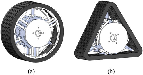
Figure 1. Structure diagram of wheel-track composite variant wheel: (a) Wheel state; (b) Track state.
2.1 The rubber track
The inner ring of the rubber track has grooves, which are divided into internal grooves and external grooves, symmetrically distributed on both sides, and the track can be engaged with the teeth of the inner driving wheel mechanism. In the wheel state, the grooves engage with the teeth of the deformation mechanism; in the track state, the grooves engage with the teeth of the inner drive wheel mechanism.
2.2 Transmission mechanism
The transmission mechanism includes a shaft, a drive connecting plate, a flat key and a fixed nut. One end of the shaft is welded to the drive connecting plate, which is used to install the wheel on the vehicle. There are four circular holes on the drive connecting plate. The bolt passes through the four circular holes on the drive connection plate. Thus, the drive connection plate is fixed to the brake disc, the flat key is inserted into the axial groove of the shaft, and the fixing nut is screwed to the other end of the shaft.
2.3 Hydraulic support mechanism
The hydraulic support mechanism consists of two rolling bearings, a stretch bracket and three identical hydraulic expansion combination parts. The inner side of the rolling bearing connects with a shaft, and the outer side of the rolling bearing connects with the stretch bracket. The three protruding parts are distributed on the stretch bracket at equal intervals along the circumference. The angle between the protruding parts is 120°, and the top of each protruding part connects with deformation mechanism.
2.4 Internal drive wheel mechanism
The inner drive wheel mechanism comprises two circular drive disks, on which there are 5 circular holes evenly distributed. The radius of the circular drive disk is larger than the radius of the telescopic spoke of the deformation mechanism on the retraction state. When the wheel is in the track state, the rubber track is tangent to the circular drive disk, and the teeth of the two circular drive disks are engaged to the inner grooves and outer grooves of the rubber track. The circular drive disk is connected to the shaft by a flat key, and the both rotate together with the shaft.
2.5 Deformation mechanism
The deforming mechanism comprises a hydraulic assembly, a telescopic spoke, a stretch plate, a telescopic support plate, a spring, a connecting pin and a support bracket. Two telescopic spokes and a hydraulic assembly form a combination, and the hydraulic assembly is placed in the middle position. The end of the combination is fixed on the surface of the support bracket, and the other end is fixed on the stretch plate. The hydraulic assembly comprises a deformation hydraulic cylinder and a deformation hydraulic rod, and the deformation hydraulic rod is extended into the deformation hydraulic cylinder. The end of the deformation hydraulic rod has a small hole. The telescopic spoke comprises a spoke fixed end and a spoke telescopic end. The spoke telescopic end extends into the spoke fixed end and can be telescopic in the spoke fixed end. There is a slot on the stretch plate. There is a small hole on the side of the stretch plate. The connecting pin is passed through the small hole at the end of the variant hydraulic rod and the small hole on the side of the stretch plate. The variant hydraulic rod and the stretch plate are connected together. The telescopic support plate is embedded in the slot of the stretch plate. The telescopic support plate can slide in the slot of the stretch plate, and is arranged on the left and right side of the stretch plate. There is a spring in the middle slot of the stretch plate, and the two ends of the spring are in contact with two the stretch support plates. The support bracket is connected with the shaft by a flat key and rotates with the shaft. The guide shaft is inserted into the hole at the outer end of the deformation hydraulic rod, and the guide bearings are installed on both sides of the guide shaft.
The structure adopts a mechanical structure to switch modes, which is stable and reliable. On complex road conditions, it becomes a track, increasing the contact area between the wheel and the ground, to ensure smooth passage. On relatively flat and hard road conditions, it changes from track to wheel, which can ensure a higher speed. As a result, the overall mobility and passing ability can be significantly improved.
3 Analysis of operation principle
3.1 Operation principle on wheel state
When the vehicle is moving in the wheel state, the transmission mechanism rotates under the driving force of the half shaft, driving the support bracket of the deformation mechanism to rotate. The support bracket drives the telescopic spoke to rotate, and the telescopic spoke drives the stretch plate to rotate. The teeth on the stretch plate engage with the inner slot and outer slot on the track, driving the rubber track movement. At this time, the wheel body is circular, and the role of the rubber track is similar to the tire of an ordinary wheel. In the wheel state, the hydraulic support mechanism is on the static state relative to the wheel under the action of gravity. Due to the action of gravity, the one set of hydraulic components and the telescopic spoke of the hydraulic support mechanism are always vertically upward.
3.2 The process of changing wheel into track
In the process of changing from wheel to track, the hydraulic oil is injected into the outer cavity of the hydraulic component of the deformation mechanism, and hydraulic oil in the inner cavity reflows. At the same time, the inner cavity of the hydraulic cylinder of the hydraulic support mechanism is injected hydraulic oil, and the hydraulic oil in the outer cavity reflows. The combined effect of both makes the deformation hydraulic rod of the hydraulic assembly indent into the deformation hydraulic cylinder. The telescopic end of the telescopic spoke retracts into the fixed end of the spoke. The stretch plate retracts accordingly, and the telescopic support plate retracts along the slot of the stretch plate, and the telescopic support plate compression spring, hydraulic rod stretches outward under the hydraulic push, pushing the guide shaft and driving the guide shaft to stretch outward together. The guide bearing contacts the inside of the track and stretches the track from wheel into track. Force equilibrium between hydraulic thrust and inertial loads transient load calculations during mode transitions is as follows.
where, Fhyd is hydraulic thrust, Fintertia inertial force, Ffriction is friction, m is mass, dv/dt is acceleration.
3.3 Operation principle on track state
When the vehicle is driving in track state, the wheel is in triangle-like shape. The rubber track is tangential to the circular drive disk of the inner drive mechanism, the teeth on the two circular drive disks of the inner drive mechanism are engaged with the inner grooves and the outer grooves on the rubber track respectively, the shaft rotates with the two circular drive disks by the flat key, and the track moves on the guide bearing. The track moves in a ‘triangle-like’ shape.
3.4 The process of changing track into wheel
In the process of changing from track to wheel, hydraulic oil is injected into the outer cavity of the hydraulic cylinder in the hydraulic support mechanism, and the hydraulic oil in the inner cavity reflows. At the same time, the inner cavity of the deformation hydraulic cylinder of the hydraulic assembly is injected hydraulic oil in and the hydraulic oil the outer cavity reflows. The combined effect of both makes the deformation hydraulic rod to indent back, and the deformation hydraulic rod of the hydraulic component extends out, pushing the telescopic support plates outward. At the same time, the spring between the telescopic support plate gradually expands, and the telescopic support plate slides out along the slot in the stretch plate under the force of the spring. The deformation hydraulic rod in the hydraulic support mechanism indents back, driving the guide shaft and guide bearing to indent back to the original state. The deformation mechanism returns to the circular state, and the track returns to a circular shape under its action.
4 Analysis of the passing ability parameters
4.1 Analysis of ground specific pressure
The ground specific pressure is an important parameter for the vehicle passing the road stably. The specific ground pressure refers to the vertical load per unit area on the contact position between the wheel and the ground.
Assume that the width of the variant wheel is the same as that of the ordinary wheel. The contact area between the rear wheel and the ground in the track state of variant wheel is a1, the contact area between the front wheel and the ground is a2, the contact area between the rear wheel and the ground of the ordinary wheel is b1, and the contact area between the front wheel and the ground is b2. It is easy to get the ratio of the ground specific pressure of the variant wheel vehicle and the ordinary wheel, as show in Equation 2.
It can be seen from Equation 2 that the ground specific pressure of the vehicle in the track state of the variant wheel is less than that of the ordinary wheel; that is, on the same road with the same tire width, the greater the contact area with the road surface is, the better the adhesion performance of the wheel to the ground is. Vehicles equipped the variant wheel have a larger ground contact area and a smaller ground specific pressure than vehicles with the regular wheel.
4.2 Analysis of ability to cross trenches
Ditches are a general term of common obstacles types encountered by special vehicles in the wild (Hou et al., 2024). The main feature of a trench is the discontinuity or pothole in the continuous road surface, and its more common forms are ditches, canals, trenches, etc. (Wang et al., 2024). Such terrain will affect the passing ability of ordinary wheels. However, wheel-track composite variant wheels can pass these complex and changeable roads well. The movement condition of the variant wheel when it passes through the ditch in the wheel state is shown in Figure 2, and the movement condition when it passes through the ditch in the track mode is shown in Figure 3.
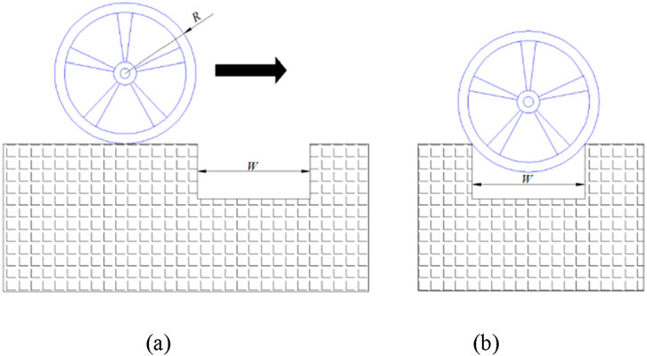
Figure 2. Passing through the ditch in wheel state: (a) before passing through the ditch; (b) the wheel is stuck in the ditch.
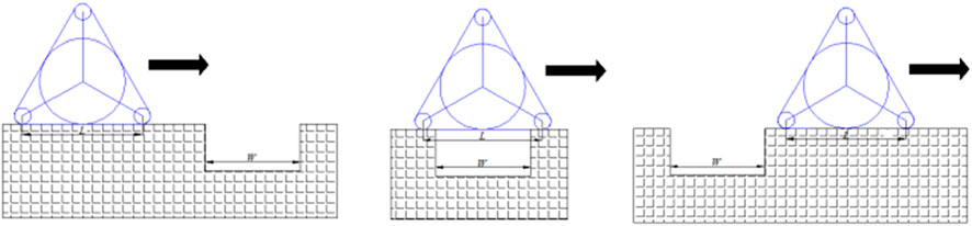
Figure 3. Passing through the ditch in track state.
It is shown in Figure 2, when the variant wheels are rolling in the wheel state and meets the ditch, if
When the variant wheels passes through a ditch in the track state, the maximum width of the ditch that can be passed depends on the position of the wheel’s center of gravity in the tracked state. In other words, when the position of the wheel’s center of gravity has not reached the ditch, one end of the track has passed the ditch. Then in this case, obstacle crossing is successful. Conversely, if the center of gravity of the wheel has reached the ditch, but the end of the track has not passed through the ditch, then the wheel will fall into the ditch and cannot pass through. The horizontal distance from the farthest contact position between one end of the track and the ground to the center of gravity is L, which is shown in Equation 3 and the width of the ditch is W. It can be obtained that the maximum ditch width that the wheel can pass through on traveling in the track mode is as shown in Equation 4:
where, L is the unilateral length when the variant wheel is in the track state, R is the radius in the wheel state, r is the radius of the guide wheel, and Wmax is the maximum width of the ditch that it can pass through in the track state.
It can be seen that by reasonably setting the values of R and r, the variant wheels in the track state can better pass the ditch than the ordinary wheel.
4.3 Analysis of passing ability characteristics on soft surfaces
When the vehicle moves on the soft surface, the ground soil is an important bearing medium supporting the vehicle, and the interaction between the vehicle and the ground leads to the force generated between them. The force is decomposed as being the horizontal and vertical to the ground, subject to the normal and tangential forces of the ground respectively. The normal force of the ground refers to the supporting force perpendicular to the ground, which reflects the bearing capacity of the ground, and the tangential force refers to the friction force along the direction of the ground, which reflects the ability of anti-shearing of the ground. The empirical formula of ground normal stress which can represent the bearing capacity of the ground soil is as shown in Equation 5:
where, σ is the normal stress of the ground, kc is the cohesive force modulus of the ground, kφ is the friction modulus of the ground, k is the ground reaction coefficient, z is the vertical deformation of the ground, b is the contact width between the track and the ground, and n is the subsidence index of the ground characteristics.
When the soil has high cohesion and cohesiveness, its ability of anti-shearing is high. The ability of anti-shearing is mainly affected by soil cohesion and ground area of track, and is expressed by Equation 6:
where, A is the contact area between the support surface of track and the ground, c is the cohesion coefficient of the soil, and Fx is the anti-shearing force.
When the ground is soft, its cohesiveness and plasticity are very small, and the road surface lacks the cohesiveness. However, under the action of the ground normal force, the soil particles squeeze each other, forming the friction between the particles; thus, a certain ability of anti-shearing produces. The friction force Fx is the ground tangential force. It is expressed as Equation 7:
where, W is the vertical load of the vehicle, and φ is the soil friction angle.
General ground is mixed soil, and its ability of anti-shearing is not only affected by soil cohesion, but also by the friction between particles and the internal friction angle. Therefore, the tangential reaction of the ground against the track is expressed as Equation 8:
The maximum ground shearing stress is shown in Equation 9 according to the Coulomb formula:
where, τmax is the maximum ground shearing stress.
From Equations 1, 5, 9, it is can been seen that soil sinkage z can be decreased by reducing ground pressure, thereby increasing τmax for enhanced traction.
When the vehicle moves on soft ground, its driving ability mainly depends on the relationship between the traction force and driving resistance, namely, the difference between the maximum tangential traction force and driving resistance is shown in Equation 10:
where, DP is the traction force of the vehicle, FHmax is the maximum tangential traction force of the vehicle, and R is the driving resistance.
The evaluation of passing ability on soft ground is shown in Equation 11. The effective traction force of the vehicle mass of per unit is the most important index to evaluate the vehicle passing ability on soft ground.
where, φ is the traction force per unit weight, and f is the driving resistance of unit mass.
It can be seen from the Equation 11 that the larger Π is, the larger the effective traction force is, and the stronger the passing ability and climbing ability of the vehicle are.
When calculating the passing ability of vehicles on soft surfaces, the slip ratio of the track is ignored. In this case, FHmax is shown in Equation 12:
Then,
From Equations 13–15 can be obtained. It can be seen from Equation 15, the same vehicle corresponds to the same road surface, and c, p, tan φ, k are constants. As the contact length with the ground L increases, the effective traction force Π of vehicle mass of per unit will also increase. The variant wheel operates in the track state; which enhances its passing ability.
5 Design of main structural parameters
5.1 Design of rubber track
The track adopts gear rubber track without joint, which has the advantages of high life, low vibration, low ground specific pressure, low noise, large traction force and little damage to the road surface. Take wheel as a reference. As the circumference is constant, the length of the track is shown in Equation 16:
Where, L is the length of the track; R is the inner diameter of the track; H is the thickness of the track.
When the variant wheel operates in track state, the track is triangular in shape. Then the groove of the triangular track is matched with the teeth of the inner drive wheel, and the number of drive wheel teeth is shown in Equation 17:
where: n is the number of the teeth of the internal driving wheel; df is the root circle; p is the pitch of track grooves.
Calculating the average pressure ratio of the track is the most convenient method to test its passing ability at the initial stage of design. The average pressure ratio of the triangular track on the ground is given by Equation 18:
where: Pp is the average pressure ratio; G is the load borne by the triangular track; L is the length of the track; b is the width of the track.
5.2 Design of the inner driving wheel
Since the inner driving wheel is the internal tangent circle of the triangular track, the radius of the inner driving wheel is shown in Equation 19:
where: r is the radius of the inner driving wheel; S is the triangular area; R is the inside diameter of the triangle track.
The position where the inner drive wheel contacts the track will be strongly squeezed, bear high load, and will be worn for long time transmission. As a result, the force on maximum dangerous cross section should be considered in the design. According to the calculation formula of mechanical bending stress of materials, the bending strength is shown in Equation 20:
where, T is the maximum bending moment of the inner driving wheel; W is the bending section coefficient; [σ] is the allowable bending stress.
5.3 Design of stretch plate and telescopic support plate
Since the track wraps the stretch plate and telescopic support plate, and the stretch plate and the rubber track match with the tooth-grooves, the stretch plate and the telescopic support plate have the same circular center and the same curvature as the track in wheel state. Therefore, the overall arc length of the stretch plate and telescopic support plate is approximately S1, as shown in Equation 21.
where, S1 the overall arc length of the stretch plate and telescopic support plate; L is length of track.
After the wheel has changed to the triangular track, the track has no contact with the stretch plate and telescopic support plate, and is separated from the two plates.
5.4 Design of deformation hydraulic rod and guide rod
The deformation hydraulic pressure rod and guide rod play an important role in the process of wheel-track transformation, and their lead is the key of deformation. The lead of the deformation hydraulic pressure rod and guide rod can be obtained by Equation 22.
where: L1 is the lead of deformation hydraulic, r is the inner drive wheel radius, R is the radius of the variant wheel on wheel state.
The length of the deformation hydraulic rod and cylinder should be at least greater than L1. Considering the complexity of the structure, the telescopic hydraulic cylinder should be used. The extended speed of the telescopic hydraulic cylinder can be changed from slow to fast. The corresponding hydraulic thrust can be changed from large too small. Its structure is compact; and is often used in engineering machinery and other travel machinery.
5.5 Design of shaft
The shaft mainly bears bending moment and torque, and the diameter of each section of shaft d should meet:
where, ηT is the torsional shear stress of the shaft (Mpa); T is the transmission torque of the shaft (N); WT is the torsion section coefficient of the shaft (mm2); P is the transmission power of axis (kW); n is the rotational speed of the axis (r/min); [τT] is the allowable torque shear stress of the shaft (Mpa).
For a solid shaft,
Equation 24 is substituted into Equation 23. The minimum diameter of the shaft should meet the following conditions in Equation 25:
6 Finite element analysis of key components
Due to the constraints of various variables, such as the selection of materials, the weight of components, process treatment methods, etc., the design scheme should be optimized. Therefore, a large number of structural analysis and structural design are carried out with computers, mathematical and mechanical tools. The finite element method is a basic analysis method that is widely used at present. It is a powerful numerical technology and widely used in the engineering industry (Ren, 2023; Yu and Gao, 2006).
In order to improve the overall processing speed, parametric processing should be adopted for each part of the variant wheel and the model should be simplified. The non-important parts, such as threaded holes, small grooves, small holes and small fillets, can be ignored. When the analysis results do not meet the requirements, the relevant major parameters and constraints can be modified so as to meet the requirements (Sun et al., 2021).
6.1 Pre-processing of model
Take the wheel as a reference. Assuming: (1) perfect track-ground contact, Ideal instantaneous hydraulic response, (2) modeling Assumptions: Uniform track-ground pressure distribution, (3) incompressible hydraulic fluid with lossless piping; (4) negligible vibration-induced mode-switching instability. The pattern of the track can be ignored. The inner drive wheel and the stretch plate can be seen as a whole with the groove of track, as they do not separate during the transmission process. In wheel state, the inner drive wheel does not transmit force; only its own gravity is applied to the shaft. Hence it can be ignored and replaced by load. The support bracket, hydraulic cylinder, deformation hydraulic pressure rod, guide rod, stretch plate and telescopic support plate can be combined into a whole for static analysis. The small hole and small boss on the stretch bracket can be filled and compressed. The bearing of the stretch bracket on the shaft can be compressed and replaced by the bearing load. In the track state, the stretch plate and the telescopic support plate are separated from the track and the match of teeth and grooves disappears. So, they can be compressed as a whole instead of concentrating load on the shaft. The convex teeth on the stretch plate are combined with the stretch plate. The part connected with the support bracket can be combined into a whole, and the position of key and groove is filled. The pin can be compressed and the joint of pin can be filled. Since the component to be analyzed is mirror-symmetric relative to the center point of the axis, we take a half for analysis. By checking the interference items and repairing them, removing the broken edges and rounded corners, repairing the missing and duplicate surfaces, and sharing the surfaces, the grid is rendered into a common node, which is convenient for grid division (Rui et al., 2022). The simplified finite element models in wheel state and track state are shown in Figures 4, 5.
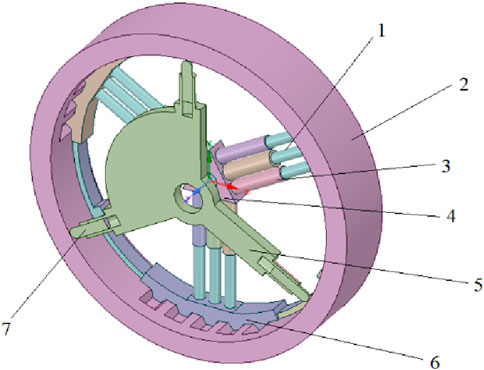
Figure 4. The simplified finite element model in wheel state 1. Hydraulic rod, 2. Rubber track, 3. Hydraulic cylinder, 4. Triangular support frame, 5. Telescopic support plate, 6. Support bracket. 7. Telescopic spokes.
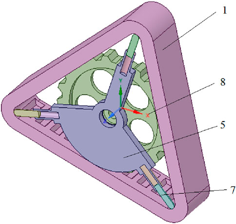
Figure 5. The simplified finite element model in track state. 1. Hydraulic rod, 5. Telescopic support plate, 7. Telescopic spokes, 8. Internal drive wheel.
After importing the analyzed model, pre-processing is carried out, mainly including type analysis, material selection, mesh division, and application of boundary conditions (Zhang, 2022). After pre-processing, the finite element models after mesh generation are shown in Figures 6–9.
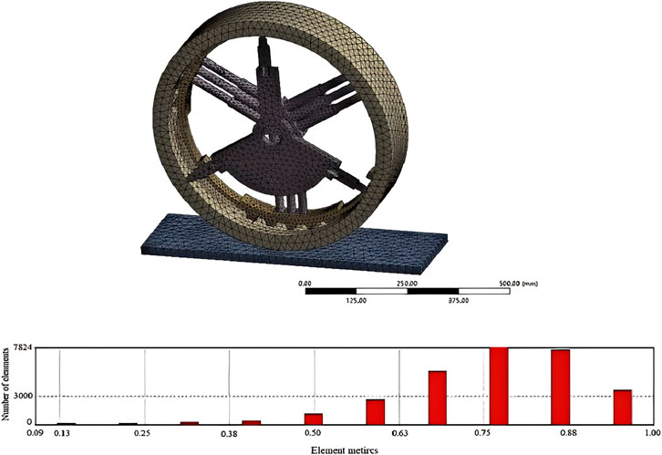
Figure 6. Grid and unit quality in wheel state.
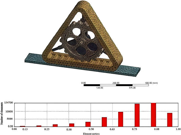
Figure 7. Grid and unit quality in track state.
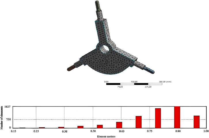
Figure 8. Grid and unit quality of the stretch bracket.
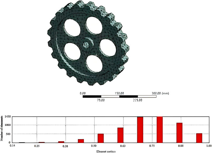
Figure 9. Grid and unit quality of the inner drive wheel.
6.2 Convergence analysis
Due to the non-linearity of geometry, material and contact, the iterative solution is required, the time sub-step ‘Substepts’ is opened, and the force convergence curve is observed. If it is found that the standard value of the force is always above the convergence value of the force, or the convergence value fluctuates around the standard value of the force, nonlinear convergence is indicated; otherwise, the setting needs to be changed. Their respective force convergence curves are shown in Figures 10–13.
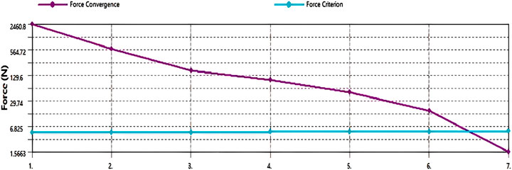
Figure 10. Force convergence curve of variant wheel in track state at static.
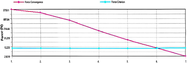
Figure 11. Force convergence curve of variant wheel in wheel state at static.
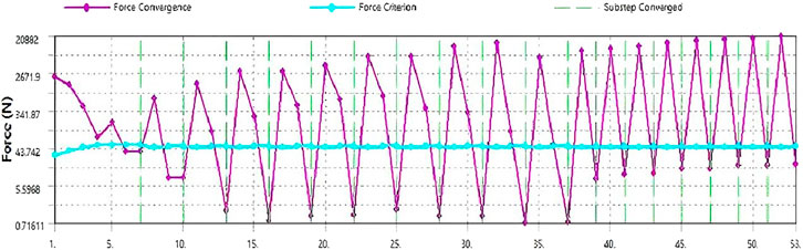
Figure 12. Force convergence curve of variant wheel in wheel state at transient.
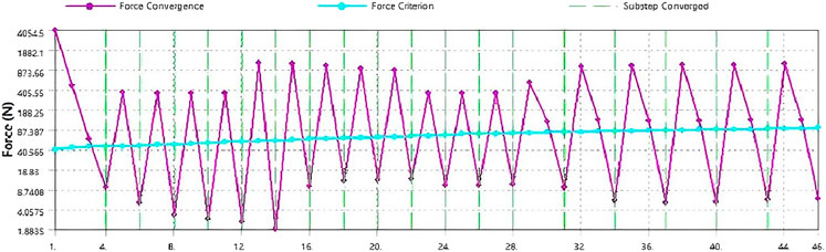
Figure 13. Force convergence curve of variant wheel in track state at transient.
In Figures 10–13, the blue line is the tolerance value of convergence, and the purple line is the residual value of calculation. It can be seen from Figures 10, 11, in the process of static linear solution, computational convergence is quickly achieved without dichotomization, and convergence occurs at 6.825 N and 12.233 N respectively. For nonlinear transient solution, it is necessary to set the start time ‘substep’ and iteration step. It can be seen from Figures 12, 13, the overall convergence effect is good, and the residual value fluctuates up and down around 43.742 N and 40.565 N respectively. Each occurrence of the green line represents a convergence, where, the initial load step is 10 N, the minimum load step is 5 N, and the maximum load step is 20 N. So, when the total load is 10000 N, starting solve at 1000 N, and the ‘substep’ of increment is from 500 N to 2000 N.
6.3 Mechanical analysis
6.3.1 Static analysis
The equivalent total strain nephogram, equivalent total stress nephogram and global deformation nephogram are obtained by the finite element method. Whether there is a stress concentration and whether the allowable stress is exceeded are analyzed according to the nephogram, and the structure is optimized reasonably. Figures 14–16 are the displacement nephogram, strain nephogram and stress nephogram in wheel state respectively. Figures 17–19. are the displacement nephogram, strain nephogram and stress nephogram in track state respectively.
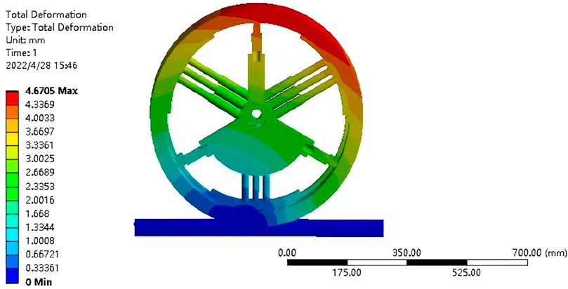
Figure 14. Displacement nephogram of variant wheel in wheel state at static.
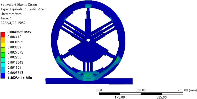
Figure 15. Strain nephogram of variant wheel in wheel state at static.
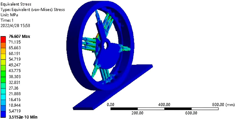
Figure 16. Stress nephogram of variant wheel in wheel state at static.
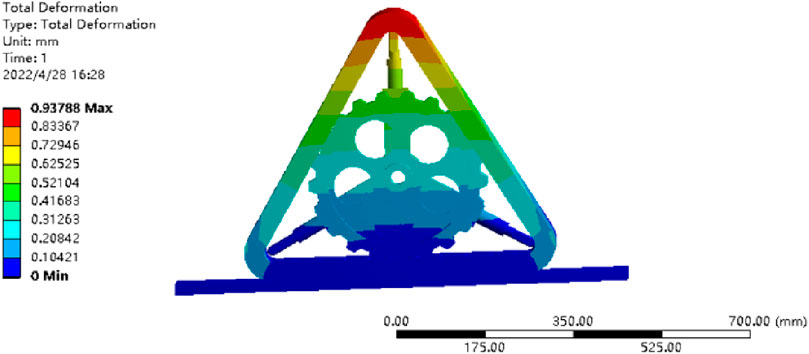
Figure 17. Displacement nephogram of variant wheel in track state at static.
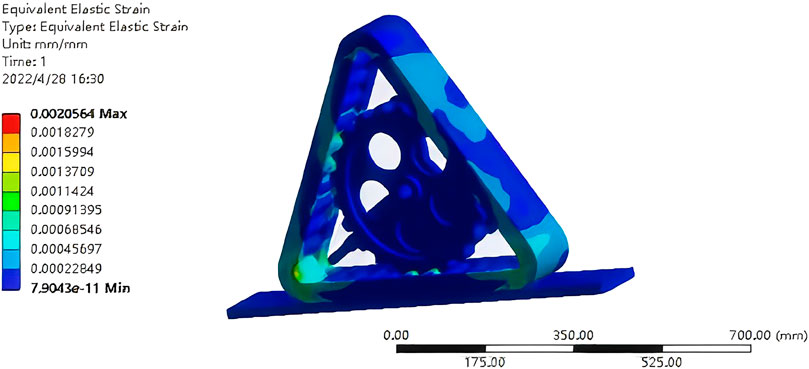
Figure 18. Strain nephogram of variant wheel in track state at static.
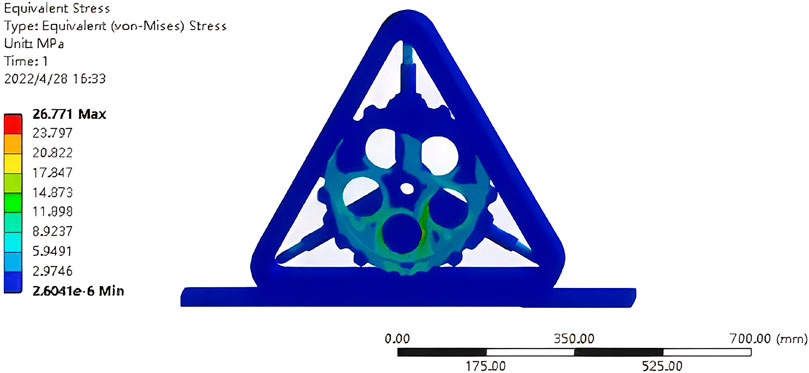
Figure 19. Stress nephogram of variant wheel in track state at static.
It can be seen from Figure 14, the overall largest deformation is located at the top of the variant wheel, and the maximum displacement is 4.6705 mm. It can be seen from Figure 15 that the maximum strain position is the contact position between the deformation hydraulic rod and the track, and the contact position between the stretch plate and the track. The maximum strain is 0.0049635 and the minimum strain is 1.4625e-14. It can be seen from Figure 16, the maximum stress is located at the bottom of the cylinder of the hydraulic cylinders on both sides connected to the support bracket, and the maximum stress is 76.607 Mpa. It can be seen from Figure 16., the maximum stress of the road surface is 4.1449 Mpa. Since the hydraulic cylinder adopts the default structural steel of the system, whose σb is 250 Mpa, the strength conditions are met.
It can be seen from Figure 17, the overall largest deformation is located at the top of the track, and the maximum displacement is 0.93788 mm. It can be seen from Figure 18, the maximum strain position is the transition position on both sides of the bottom end of the track, the maximum strain is 0.0020564, and the minimum strain is 7.9043e-11. It can be seen from Figure 19, the maximum stress is located at the drilling position of the inner drive wheel, and the maximum stress is 26.771 Mpa. As the internal drive wheel adopts the default structural steel of the system, whose σb is 250 Mpa, it meets the strength requirement.
6.3.2 Transient analysis
Transient dynamic analysis is a method used to analyze the dynamic response of structures when the load varies with time. It is used to determine the time-varying displacement, strain and stress when the structure is subjected to a random combination of steady-state loads, transient loads and harmonic loads (Chen, 2024; Zhao et al., 2022). Element type selection of Hexa20 is adopted. Explicit dynamics with Mooney-Rivlin rubber modeling is employed. The driving speed was set to 40 Km/h in wheel state and 20 km/h in track state respectively for transient analysis. The displacement nephogram, strain nephogram and stress nephogram in wheel and track state at transient are obtained, as shown in Figures 20–22.
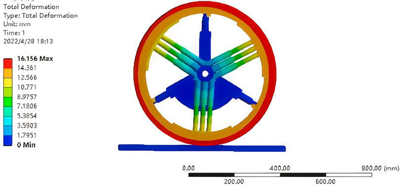
Figure 20. Displacement nephogram of variant wheel in wheel state at transient.
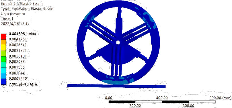
Figure 21. Strain nephogram of variant wheel in wheel state at transient.
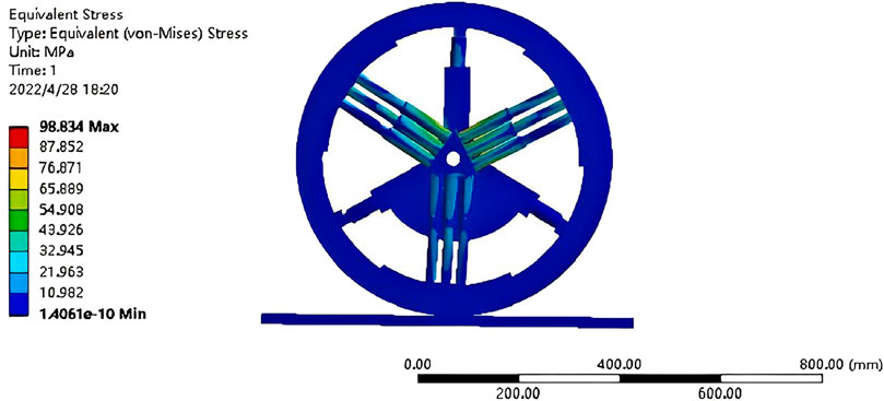
Figure 22. Stress nephogram of variant wheel in wheel state at transient.
It can be seen from Figure 20, the overall largest deformation is located at the edge of the track, and the maximum displacement is 16.156 mm. It can be seen from Figure 21 that the maximum strain is located at the connection between the stretch plate and the track. The maximum strain is 0.0046981 and the minimum strain is 7.0052e-15. It can be seen from Figure 22 that the maximum stress is located at the bottom of the cylinder of the hydraulic cylinder connected to the support bracket, and the maximum stress is 98.834 Mpa. Since the hydraulic cylinder adopts the default structural steel of the system, whose σb is 250 Mpa, it meets the strength requirements.
It can be seen from Figure 23, the largest overall deformation is located at the tooth end of the inner drive wheel, and the maximum displacement is 2.2349 mm. It can be seen from Figure 24, the maximum strain position is the fillet transition position on both sides of the bottom end of the track, The maximum strain is 0.0020512 and the minimum strain is 0. It can be seen from Figure 25., the maximum stress is located at the drilling position of the inner drive wheel, The maximum stress is 500.13 Mpa, which needs to be optimized.
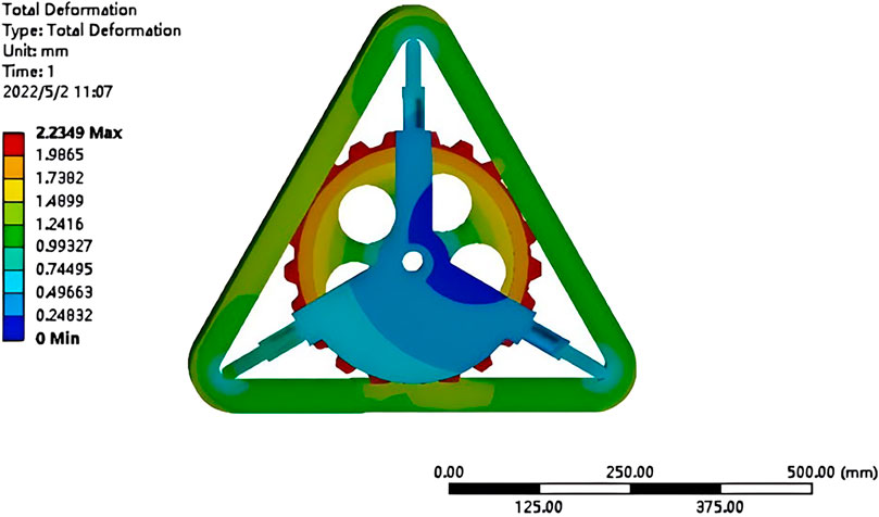
Figure 23. Displacement nephogram of variant wheel in track state at transient.
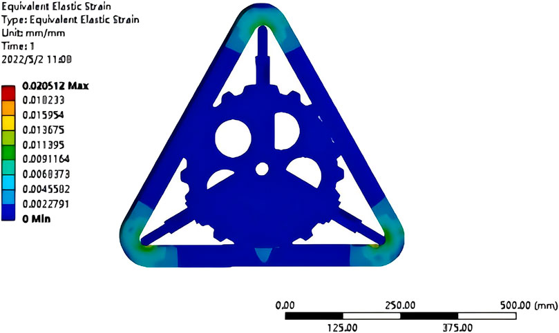
Figure 24. Strain nephogram of variant wheel in track state at transient.
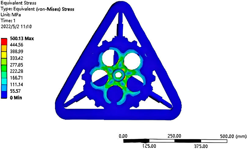
Figure 25. Stress nephogram of variant wheel in track state at transient.
6.4 Optimization of key components
Topology optimization of internal drive wheel. Through the static and transient finite element analyses of the variant wheel, it is found that the deformation of the inner drive wheel and the stress of the center hole position are too large in track state at the transient analysis Hence the optimization of material parameters and size parameters is needed.
When the inner drive wheel is not drilled, its stress, strain and total deformation are shown in Figures 26–28.
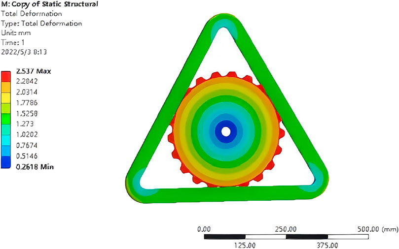
Figure 26. Displacement nephogram of variant wheel in track state at transient when the inner drive wheel is not drilled.
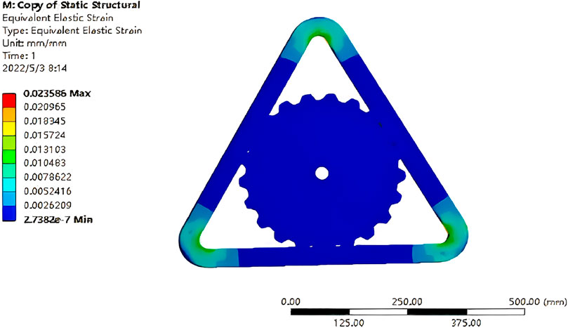
Figure 27. Strain nephogram of variant wheel in track state at transient when the inner drive wheel is not drilled.
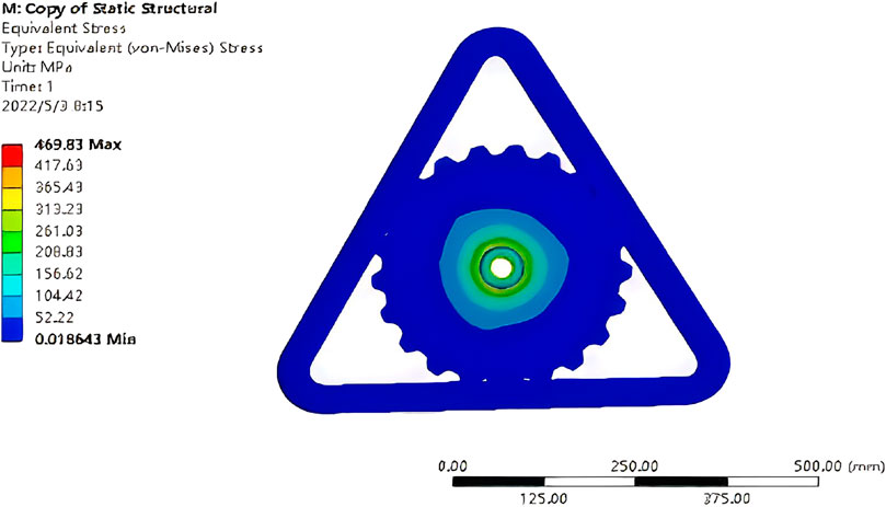
Figure 28. Stress nephogram of variant wheel in track state at transient when the inner drive wheel is not drilled.
It can be seen from the equivalent stress in Figure 28, the stress distribution is mainly around the hole, and the stress at the tooth meshing position is 104.52 Mpa. The stress concentration area should be avoided as far as possible when designing the opening position. The shape optimization module is used to change the shape of the stretch bracket to achieve the purpose of weight reduction under the premise of satisfying strength, stiffness and life. The optimization results are shown in Figure 29.
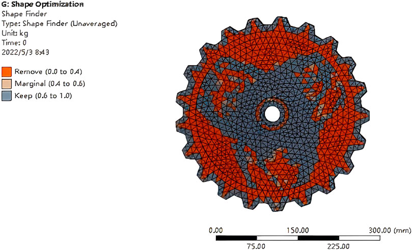
Figure 29. The topological structure of the inner drive wheel after optimization.
Response surface optimization of the internal drive wheel. The stress distribution of the inner drive wheel is mainly concentrated in the open hole area, and the stress concentration position is on the side cylindrical surface of the open hole. By controlling the precision of the grid of the cylindrical surface, the stress change is observed to determine whether it is a stress singularity.
The size of the meshing unit is defined as a variable parameter. Its range is from 2 mm to 10 mm, and the results are shown in Table 1. Maximum deformation and maximum stress corresponding to different holes are shown in Table 2
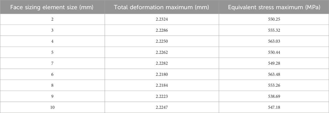
Table 1. Maximum strain and average stress corresponding to different grids.
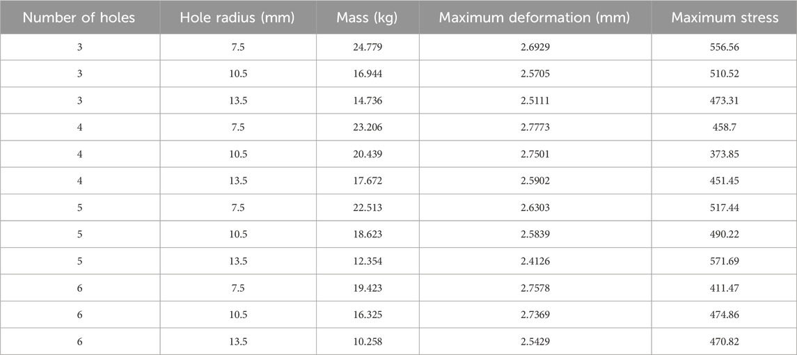
Table 2. Maximum deformation and maximum stress corresponding to different holes.
The kriging method is used to solve the response surface optimization, and the results are shown in Table 3.
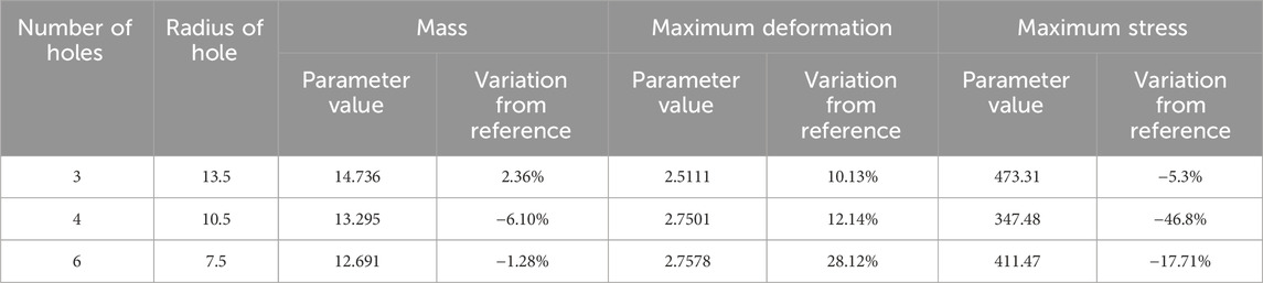
Table 3. Response surface optimization results by kriging method.
According to the analysis of Table 3, three groups of candidate points are generated. Compared with the original design scheme, the stress of the first group of candidate points is reduced by 5.3%–473.31 Mpa, the deformation is increased by 10.13% to 2.5111 mm, and the mass is increased by 2.36%–14.736. In the second group of candidate points, compared with the original design scheme, the stress is reduced by 46.8%–347.48 Mpa, the deformation is increased by 12.14% to 2.7501 mm, and the mass is increased by 6.10%–13.295 kg. In the third group of candidate points, compared with the original design scheme, the stress is reduced by 17.71%–411.47 Mpa, the deformation is increased by 28.12% to 2.7578 mm, and the mass is reduced by 1.28%–12.691. Therefore, in summary, candidate point 2 is the best optimization result, that is, the number of holes is 4 and the thickness of holes is 10.5 mm.
7 Test verification
7.1 Deformation test
According to the design results of and optimization, a prototype is made and tested. The test results show that the variant wheel can expand and retract smoothly, the retract time is 6.3 s, and the extension time is about 7.7 s. The total time of extension and retraction is 15 s, which is much shorter compared with the wheel and track changing time (20–30 min). It verifies that the deformation principle of the variant wheel is correct and the design scheme is feasible.
7.2 Climbing step obstacle test
The variant wheels are installed on all-terrain vehicle (ATV), climbing step obstacle test of is shown in Figure 30. Figure 30a shows that when the variant wheel encounters the convex obstacle, it expands and changes into track and rests on the step. Figure 30b shows that the track forms a bridge between the wheel and the steps, and the vehicle climbs the steps smoothly.
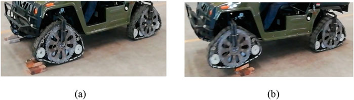
Figure 30. ATV equipped with variant wheel climbing a step obstacle: (a) The variant wheel encountering the convex obstacle; (b) The vehicle climbing the steps.
7.3 Passing the grass terrain test
The passing grass terrain test is shown in Figure 31. The test ground is an uneven and weedy mud depression. From the test, it can be seen that ATV equipped with variant wheels can pass flexibly, while weeds and mud puddles have little influence on moving, and it can pass the grassland smoothly.

Figure 31. ATV equipped with variant wheel passing the grass terrain test.
7.4 Test results of variant wheel prototype
After repeated tests, the test comparison results of the variant wheel and the wheel are shown in Table 4. By analyzing Table 4, it can be seen that the maximum speed of the ATV equipped with the variant wheel is reduced due to the addition of a variant mechanism inside the variant wheel. However, due to the uncertainty of field road conditions, the vehicle generally cannot run at full speed. Therefore, it has little effect on the mobility of the vehicle, and the maximum climbing step height and maximum climbing grade of variant wheel has a significant increase compared with the wheel, in which the maximum climbing step height is increased by 130% and the maximum gradeability is increased by 94%.
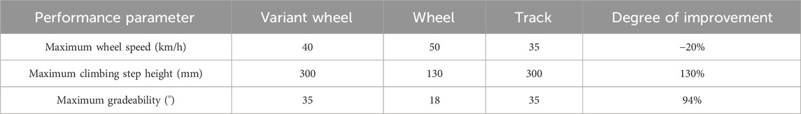
Table 4. Performance test results of variant wheel.
8 Conclusion
In order to improve the adaptability of modern special vehicles to complex road conditions, the paper analyzes the research status of ground travel mechanism at home and abroad, and develops a wheel-track composite variant wheel which can switch between wheel and track. It solves the problems of poor crossing ability of wheeled travel mechanism, poor mobility of tracked travel mechanism, time-consuming of wheel-track replacement. In the premise of not reducing mobility, the passing ability of the special vehicle is improved.
According to the road conditions of special vehicles and the existing solutions, a scheme composed of rubber track, hydraulic support mechanism, transmission mechanism, deformation mechanism and internal driving wheel mechanism is proposed. The scheme has a compact structure, high obstacle crossing efficiency and strong adaptability to terrain.
The operation principle and passing ability parameters of the variant wheel are analyzed, and the rationality of the design scheme is further verified. On this basis, the main structural parameters such as the rubber track, inner drive wheel, stretch plate, hydraulic cylinder and guide rod are designed using the mechanical design principle.
According to the design results, the finite element method is used to carry out transient and static structural analysis, and the parts with the greatest stress and deformation are obtained. In order to make the stress and deformation meet the requirements of strength and stiffness, parametric processing is used to optimize the response surface parameters.
By combining the scheme design, theoretical analysis and optimization design, and according to the optimization results, a prototype is made, and the deformation test and obstacle crossing test are carried out. The results show that the prototype can quickly switch between wheel and track, and the switching time is 15s. At the same time, the maximum climbing step height is increased by 130% and the maximum gradeability is increased by 94%. The mobility and obstacle crossing ability of the special vehicle are comprehensively improved. It provides theoretical basis and technical support for the design and application of variant wheels. Further, reliability will be verified so that the variant wheels could be commercialized. And manufacturing process is further studied to improve the manufacturing accuracy and reduce the manufacturing cost.
Data availability statement
The original contributions presented in the study are included in the article/supplementary material, further inquiries can be directed to the corresponding author.
Author contributions
JM: Conceptualization, Validation, Writing – original draft. PZ: Formal Analysis, Investigation, Methodology, Writing – review and editing. KS: Formal Analysis, Supervision, Writing – review and editing. MA: Validation, Writing – review and editing.
Funding
The author(s) declare that financial support was received for the research and/or publication of this article. This research was funded by the Xingtai Youth Talent Plan Project, grant number 2021ZZ034.
Acknowledgments
We would like to extend our appreciation to King Saud University for funding this work through the Ongoing Research Funding program (ORF-2025-481), King Saud University, Riyadh, Saudi Arabia.
Conflict of interest
The authors declare that the research was conducted in the absence of any commercial or financial relationships that could be construed as a potential conflict of interest.
Generative AI statement
The author(s) declare that no Generative AI was used in the creation of this manuscript.
Any alternative text (alt text) provided alongside figures in this article has been generated by Frontiers with the support of artificial intelligence and reasonable efforts have been made to ensure accuracy, including review by the authors wherever possible. If you identify any issues, please contact us.
Publisher’s note
All claims expressed in this article are solely those of the authors and do not necessarily represent those of their affiliated organizations, or those of the publisher, the editors and the reviewers. Any product that may be evaluated in this article, or claim that may be made by its manufacturer, is not guaranteed or endorsed by the publisher.
References
Chen, T. W. (2024). Analysis of automobile wheel hub drop hammer test based on transient dynamics. Autom. Appl. 65 (10), 170–172.
Cui, Y. N., Luo, Z. R., Shang, J. Z., and Zhang, Z. X. (2018). Machine design of a reconfigurable wheel-track hybrid mo-bile robot with multi-locomotion. J. Harbin Inst. Technol. 50 (7), 80–86.
Gao, Z. C., and Zhang, L. P. (2023). A docking mechanism de-sign for a reconfigurable wheeled robot. China South. Agric. Mach. 54 (3), 138–140.
He, Y. L., Guo, A. F., Liu, Q. C., Jiang, T., Xu, R., and Zhang, X. W. (2022). Structural design and analysis of a multi-functional wheel-tracked excavator. Mach. Des. Res. 38 (3), 210–215+221.
Hou, B. Y., Gong, R., Wang, Z. G., Ren, B., and Chen, C. (2024). Simulation analysis on maneuverability of tracked rescue platform. Mech. Eng. 51 (1), 110–114.
Kim, J., Kim, Y. G., and Kwak, J. H. (2010). “Wheel & track hybrid robot platform for optimal navigation in an urban environment,” in IEEE 2010: proceedings of SICE annual conference, 18–21.
Kim, Y. G., Kwak, J. H., and Kim, J. (2010). “Adaptive driving mode control of mobile platform with wheel-track hybrid type for rough terrain in the civil environment,” in IEEE 2010: international conference on control (Singapore: Automation and Systems), 7–10.
Kim, Y. G., Kwak, J. H., Hong, D. H., Kim, I. H., Shin, D. H., and An, J. (2012). Autonomous terrain adaptation and user-friendly tele-operation of wheel-track hybrid mobile robot. Int. J. Precis. Eng. Manuf. 13 (10), 1781–1788. doi:10.1007/s12541-012-0234-9
Liu, Y., Xie, X., Zhou, X., and Wang, L. (2019). Summary of Re-search on wheel-track composite chassis. Mod. Manuf. Technol. Equip. 15 (4), 87–90.
Michaud, F., Létourneau, D., Arsenault, M., Bergeron, Y., Cadrin, R., Gagnon, F., et al. (2005). Multi-modal locomotion robotic platform using leg-track-wheel articulations. Aut. Robots 18 (2), 137–156. doi:10.1007/s10514-005-0722-1
Ren, Z. (2023). Fatigue analysis and multi-target optimization design of an aging assistance mechanism based on ANSYS workbench. Automation Instrum. 29 (10), 251–255+259.
Rui, H. B., Cao, W., and Li, L. L. (2022). Structure design and analysis on obstacle-crossing capability of wheel-shoe com-pound deformation wheel based on displacement gear. Jour-nal Mach. Des. 39 (7), 74–83.
Shang, J. Z. (2006). Research on the locomotion mechanism and system of space exploring robot. Published PhD thesis. Wuhan: Huazhong University of Science and Technology.
Si, G. M., Liu, L., Zhao, M., Song, X. L., Shi, Y., and Wang, C. H. (2019). Design and calculation of hydraulic system for wheel-track composite chassis. Road Mach. Constr. Mech. 36 (3), 112–116.
Song, Q. J., Li, X. W., Zhang, F. G., and Xiong, S. S. (2024). Exploration and model validation of centrifugal force influence boundary of tracked vehicle dynamic model. Mod. Mach. 50 (2), 5–11.
Su, J., Li, C. M., and Fan, Z. Y. (2017). Analysis on sprocket and track mesh power loss of wheel-tracked vehicle. Veh. Power Technol. 36 (1), 15–20.
Sun, C. L., Xu, X. J., Wang, L. H., Tang, Y. j., Yang, Y. C., and Huang, Z. H. (2021). Research on hydrodynamic performance of a blended wheel-track amphibious truck using experimental and simulation approaches. Ocean. Eng. 29 (10), 251–255+259.
Tadakuma, K., Tadakuma, R., and Maruyamaet, A. (2010). “Mechanical design of the wheel-leg hybrid mobile robot to realize a large wheel diameter,” in IEEE 2010 international conference on intelligent robots and systems, Taipei, Taiwan, China, 20–26.
Wang, B. C., Sun, S. F., Zhang, J. Y., and Liu, J. H. (2024). Chassis trafficability simulation and experiment of desert crawler transport vehicle. For. Eng. 40 (4), 186–195.
Wang, H., An, Y., Cui, S. L., and Yang, C. M. (2024). Design and simulation of forest transporter with adaptive center of gravity adjustment. J. Chin. Agric. Mech. 45 (3), 148–155.
Yu, W. W., and Gao, B. J. (2006). “Application of ANSYS in machinery and chemical equipment,” Beijing, China: China Water Resources and Hydropower Press.
Zhang, L. (2022). Finite element method and application Ba-sis of ANSYS program. Beijing, China: Science Press.
Zhao, J. X., Huang, T., Song, K. X., Zhang, X. B., Jiang, Y. N., and Hao, L. C. (2022). Structure optimization of bellows based on transient dynamic analysis. J. Netshape Form. Eng. 14 (12), 191–198.
Zhou, F. L. (2019). Research on configuration design and passing ability of multi-motion robot based on rim deformation. Changsha, Hunan, China: National University of Defense Technology. PhD thesis.
Zhou, F., Xu, X., and Xu, H. (2017). “A multimodal hybrid robot with transformable wheels,” in IEEE 2017: international conference on real-time computing and robotics (Taichung, Taiwan, China), 10–15.
Zhou, K. Q., Xie, X., Zheng, B., and Zhuang, S. X. (2020). De-sign of compound deformation wheel based on hydraulic drive. J. Mil. Transp. Univ. 22 (5), 45–50.
Zhou, F., Xu, X., Xu, H., Chang, Y., Wang, Q., and Chen, J. (2020). Implementation of a reconfigurable robot to achieve multimodal locomotion based on three rules of configuration. Robotica 38 (8), 1478–1494.
Keywords: special vehicle, wheel-track composite, variant wheel, finite element method, optimization design
Citation: Ma J, Zhang P, Shao K and Aljuaid MM (2025) Optimization design of wheel-track composite variant wheels for special vehicles base on finite element method. Front. Mech. Eng. 11:1717059. doi: 10.3389/fmech.2025.1717059
Received: 01 October 2025; Accepted: 10 October 2025;
Published: 04 November 2025.
Edited by:
Liguo Zang, Nanjing Institute of Technology (NJIT), ChinaReviewed by:
Zhan Changshu, Northeast Forestry University, ChinaLiwei Shi, Shandong University of Technology, China
Copyright © 2025 Ma, Zhang, Shao and Aljuaid. This is an open-access article distributed under the terms of the Creative Commons Attribution License (CC BY). The use, distribution or reproduction in other forums is permitted, provided the original author(s) and the copyright owner(s) are credited and that the original publication in this journal is cited, in accordance with accepted academic practice. No use, distribution or reproduction is permitted which does not comply with these terms.
*Correspondence: Jianwei Ma, bWFqaWFud2VpQGhldnV0ZS5lZHUuY24=