 Michael D. Gibson
- Department of Architecture, Kansas State University, Manhattan, KS, United States
Homes in the U.S. account for a substantial share of energy use and emissions, while the shortage of affordable housing underscores the need for new design and construction approaches. The Zero Carbon Microhome, designed by architecture students in the Net Positive Studio at Kansas State University, demonstrates how hempcrete and hemp fiber can be integrated into a prototype for affordable infill housing that achieves both annual net zero energy and net zero carbon over its lifespan. Hemp’s use in the project is central to reducing embodied emissions in the structure and enclosure of the home. A carbon assessment incorporates emissions from the hempcrete and hemp fiber insulation to evaluate their role in achieving net zero carbon. An accompanying energy analysis examines the thermal properties of these materials and demonstrates how the project attains net zero energy, with operational carbon reduced and offset by renewable energy. The hempcrete mixture is detailed, along with factors influencing its performance. Together, these strategies offer a replicable model for applying hemp and hempcrete in the pursuit of affordable, net zero energy, net zero carbon housing.
1 Introduction
Today, the U.S. faces an unprecedented housing crisis across three main fronts: housing supply, housing affordability, and housing sustainability. In Kansas, a state report forecast housing demand to be twice the rate of home building, with a deficit growing at 1,400 to 2,300 housing units per year (Kansas Housing Resources Corporation (KHRC), 2021). Across the Midwest region only 3% of completed new homes were sold for under $150 k, while 59% were sold for over $400 k in 2023 (U.S. Census, 2023b). Meanwhile, 21.3% of Kansas homeowners with a mortgage pay more than 30% of their income on mortgage payments, and 40.4% of Kansas renters pay more than 30% of their income on rent (U.S. Census, 2023a,b). In terms of energy and emissions impacts, homes in the U.S. use 15% of the energy consumed nationally, exceeding the commercial sector’s 13%, while accounting for a surprising 41% of natural gas and 44% of electricity consumption (U.S. Department of Energy, Energy Information Administration, 2024a,b). Similarly, homes are responsible for 17.7% of energy-related greenhouse gas emissions (GHGe), exceeding the commercial building sector’s 15.7% (U.S. Department of Energy, Energy Information Administration, 2024a,b), with the typical U.S. household’s GHGe from utilities being 60% greater than those emitted from driving (Gibson, 2024b). Energy further contributes to households’ economic strain, where in the Midwest 21% of households reported some form of energy insecurity in 2020 (U.S. Department of Energy, Energy Information Administration, 2022), while inefficient, unimproved homes in the region contribute to negative health of occupants (Wilson et al., 2023).
Since 2018, the Net Positive Studio has responded to these housing challenges as a service-learning studio in the College of Architecture, Planning, and Design at Kansas State University, where students in the Master of Architecture program design and build affordable, net zero energy homes with non-profit partners, under the leadership of the author, who is a licensed architect. The Zero Carbon Microhome (ZCMH, Figure 1) will be the 11th project completed by the Net Positive Studio; since its inception, 30 homes have been replicated by the studio’s partners in Kansas and Missouri, including a net zero home just a few blocks away, completed in 2022 (Figure 2) within under the same collaboration as the ZCMH.
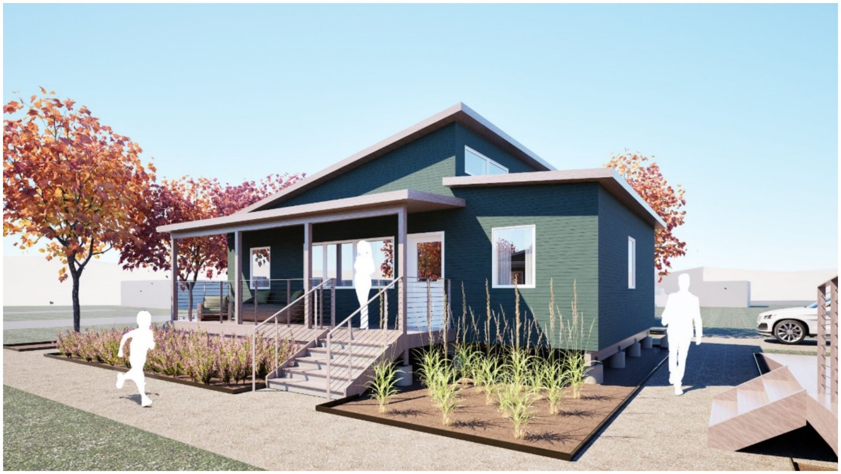
Figure 1. A rendering of the zero carbon microhome design (Source: Net Positive Studio, K-State).
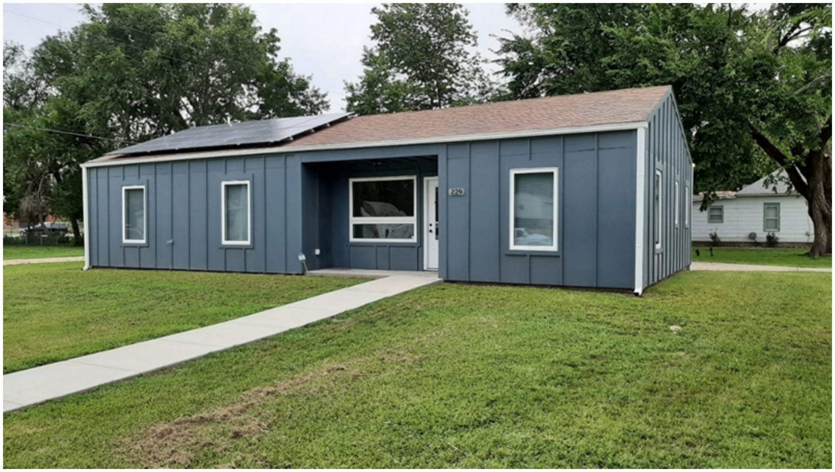
Figure 2. The Ogden #1 Workforce prototype home, completed by the Net Positive Studio in 2021 in Ogden, Kansas. The 1,200 ft2 home was prefabricated by the studio using polyurethane structural insulated panels, and constructed by Workforce Solar Housing Partnership collaborating organizations for Habitat for Humanity of the Northern Flint Hills.
The goals of the ZCMH project extend from the mission of the studio: to balance the need for an affordable, replicable home design with performance that can achieve net zero site energy (i.e., the home produces as much or more energy than it uses on a yearly basis, when accounted for at the site). Attaining these goals require students in the studio to exercise a combination of conceptual creativity, design excellence, integration of passive design principles, rigorous detailing and document development, and the use of advanced tools for energy modeling and analysis; for six projects, including the ZCMH, the studio also prefabricated the house, using a model-based process required by prefabrication to support performance goals of the project. For the ZCMH project, the studio added a new goal: to achieve or approach “zero carbon” in the project’s carbon balance, while demonstrating a home that could sell for $150,000 or less, in a community where the current (August 2025) median listed home price is $312,450 and new small homes in the 1,200 to 1,600 ft2 range typically sell for over $350,000 (Realtor.com, 2025).
In order to balance affordability, replicability, and performance, the Net Positive Studio uses a “Lean Tech” approach to net zero energy, wherein expensive, complex technologies are eschewed to prioritize low-cost, high-impact, simple design strategies (Gibson, 2024b): these include right-sizing the home, incorporating climate-appropriate passive strategies, emphasizing adaptive comfort, using high-efficiency heat pumps, optimizing envelope design using energy modeling, and setting reasonable net zero energy targets based on affordable, cooperatively-installed photovoltaic systems. These same priorities serve as a framework for the zero carbon approach to the ZCMH, demonstrating a path to radically reducing GHGe that results in an affordable, replicable, and well-designed home.
To reduce embodied GHGe, the ZCMH set out to use carbon-negative hempcrete (aka hemp-lime) and hemp fiber as its insulation system, eliminating all foam and petrochemical-derived insulation from its building envelope to reduce embodied emissions. An elevated pier foundation system would further reduce the use of carbon-intensive concrete in its structure. With regards to operations GHGe, the ZCMH would produce emissions-free renewable energy on-site, offsetting emissions from grid-based energy, while avoiding direct emissions as an all-electric home. Tracking the design’s energy performance was important, because hempcrete and hemp fiber insulation perform differently than the insulation materials used by the studio in the past (Gibson, 2024a). The ZCMH prototype would need to achieve net zero energy in the challenging IECC Climate Zone 4a in which Manhattan is located, a Dfa in the Köppen climate classification system with heat extremes similar to Mediterranean Europe yet with cold extremes in line with Poland. While embodied and operations GHGe were the primary focus of the ZCMH, transport GHGe are relevant in that the greater Manhattan area employs a large number of commuters. Community emissions could be reduced by infill homes like the ZCMH that could be built in existing neighborhoods, closer to places where people work, access services, and access amenities.
The Workforce Solar Housing Partnership (WSHP) collaboration was also critical to realizing the ZCMH, which joins Kansas State University, Manhattan Area Technical College (MATC), Habitat for Humanity of the Northern Flint Hills (HHNFH), the Home Builder’s Institute of Ft. Riley (whose students are enlisted soldiers in the U.S. military), the Flint Hills Job Corp, the Flint Hills Renewable Energy and Efficiency Cooperative, and the Manhattan Housing Authority. The mission of the partnership is to demonstrate sustainable and affordable building methods while educating the emerging construction workforce in techniques and building methods that are critical to meeting future housing needs. Homes are built with HHNFH serving as the general contractor and are subsequently sold to income-qualified homeowners. Thus far students, teachers, and leadership from all WSHP organizations have participated in the ZCMH, underscoring the interest in hemp materials and the capability for hemp-integrated building methods to be replicated in the field.
2 Materials and methods
2.1 Hemp and hempcrete in building
Industrial hemp was legalized in the U.S. by the Farm Bill of 2018, and future industrial hemp production is expected to increase in areas favorable for hemp cultivation, as growing is expanded for hemp’s high-protein seeds, leading to more raw material for use in construction. Hemp’s use in insulation comes from two raw materials, which come from the dried stalks of the plant: the stalk’s woody inner hurd, also known as shiv, and the stalk’s outer bast fibers. While there are several ways to use hemp for insulation, the ZCMH employs hemp using two primary methods: hempcrete and hemp fiber batts. Hempcrete combines hemp hurd, a binder (typically lime-based), and water, which is mixed and then tamped in place around a load-bearing structure to provide non-structural, porous insulating infill. The second method for incorporating hemp is in a precut batt made from hemp fiber, similar in application to other fiber batts such as fiberglass or mineral wool.
Integrated in the ZCMH, hempcrete and hemp fiber offer a compelling alternative to contemporary foam and fiber insulations, which rely on energy-intensive industrial processes, and for some materials, energy-intensive petrochemicals. Industry-average embodied carbon for common building materials deployed in an R-10 wall assembly are 1.2 kgCO2e/m2 for fiberglass batt, 7.2 kgCO2e/m2 for polyisocyanurate foam, and 8.6 kgCO2e/m2 for extruded polystyrene (Builders for Climate Action, 2025). On the other hand, hemp-derived insulations are generally carbon negative, due to stored (sequestered) carbon that is part of the raw material, offsetting the emissions associated with harvesting, processing, and production. For the same R-10 insulation, hemp fiber batts have just −0.25 to −1 kgCO2e/m2 of embodied carbon while hempcrete can range from −11 to −17 kgCO2e/m2, with hempcrete’s negative carbon footprint aided by the absorption of CO2 during curing (Arehart et al., 2020).
Hemp fiber and hempcrete present different advantages and disadvantages. Hemp fiber insulation batts are lighter than hempcrete, at 2.18 lbs/ft3 (35 kg/m3) (Hempitecture, 2025b) while hempcrete dry density ranges from 21 to 62 lbs/ft3 (330 to 1,000 kg/m3) (Jami et al., 2018), depending on the hempcrete’s composition. Hempcrete’s density makes it difficult to use in roofs and ceilings, although it is occasionally used in this application. Hemp fiber batts have a conductivity of 0.040 W/mK (Hempitecture, 2025b), which is nearly identical to fiberglass insulation, although greater density gives the heavier hemp batts some thermal advantage. Hempcrete’s conductivity is greater (worse) than fiber, ranging from 0.09 to 0.54 W/mK (Jami et al., 2018), though its thermal mass resists dynamic heat flows, providing beneficial thermal buffering. Lastly, acceptance by local regulatory jurisdictions for hempcrete and hemp fiber varies. Hempcrete was introduced in the 2024 IRC as an addendum (see Appendix BL; International Code Council, 2024), which most jurisdictions have yet to adopt. Hemp fiber is not yet recognized prescriptively in the code, leaving usage dependent on local approval. For the ZCMH, the local jurisdiction (the small community of Ogden, KS) permitted hempcrete and hemp fiber use without requiring special approval or additional submittals.
2.2 Challenging traditional hemp integration
In traditional formed-in-place hempcrete, mixed hempcrete is dumped into wood framing, where it is tamped around the wood structure, while temporarily held by shuttering boards that are moved every two to three feet in height to form walls, roofs, or ceilings. Finished hempcrete both dries and cures (this author and others tend to use these terms interchangeably). While excess water evaporates from the material, the lime-based binder undergoes a chemical curing process called carbonation, where CO2 is absorbed to form calcium carbonate in the porous hempcrete (Sáez-Pérez et al., 2020), holding the hempcrete together and giving it strength. In a conventional hempcrete build, temporary shuttering forms both sides of placed hempcrete (two-sided forming) and is removed soon after for curing, after which protection from rain, excessive heat, and freezing is critical (Sáez-Pérez et al., 2020) to prevent damage.
Practitioners in the U.S. who use traditional tamped-in-place hempcrete building techniques staunchly assert two-sided forming is required for curing, to allow hempcrete to “breathe.” However, contemporary wood framing benefits greatly from structural sheathing, which resists lateral and uplift forces; without it, traditional hempcrete that encases wood structure needs other means to resist these forces. Secondly, thick hempcrete walls cure like lime mortars, inevitably leaving some uncured lime in the interior (Arehart et al., 2020) where less CO2 is available, even when exposed on two sides.
The use of a permanent form on one side of hempcrete, referred to as single-sided forming, is common in Europe in both the tamped hempcrete and hempcrete spraying industry, with a variety of products used as a permanent form on either the inside or outside (Stanwix and Sparrow, 2014). Prior hempcrete research by the author (Figure 3) investigated the potential to form hempcrete against permanent, semi-permeable, weather-resistant wood sheathing, where placement required shuttering on just one side (Gibson, 2024a). Hempcrete successfully cured against the sheathing in these experiments, which itself was not harmed by the damp hempcrete, while providing necessary lateral bracing and protection from weather, and also simplifying hempcrete placement (Gibson, 2024a). Many materials, including OSB sheathing and drywall, allow the diffusion of CO2 through pores and can be used to clad finished hempcrete that still needs access to CO2 to cure.
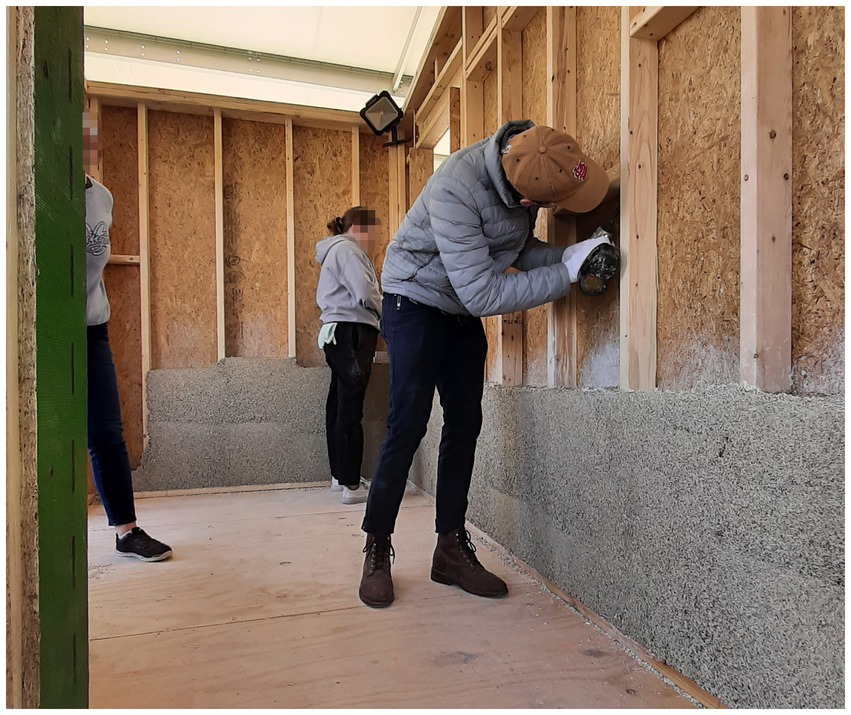
Figure 3. Single-sided hempcrete forming against wood sheathing, successfully used by the author and his students in a 2023 project (Source: Author).
For the ZCMH, single-sided forming was taken a step further and the project’s hempcrete was integrated into an elevated floor assembly. Horizontal hempcrete was placed in the open cavities of the floor panels against a layer of sheathing, which was pre-installed under the framing. This assembly offered the possibility of easier hempcrete placement and a shorter drying period. With a robust amount of hempcrete in the ZCMH floor, hemp fiber batts were utilized in the walls and roof/ceiling assembly, where the batts were lighter and easier to install.
2.3 Challenging typical binder mixes
Most traditional hempcrete builders in the U.S. use binder made exclusively from lime and pozzolanic clays, shying away from binder components such as Portland cement, a practice also reflected in popular general-audience texts. In reality, in the more mature European hempcrete industry, it is the norm to use binders with a variety of non-lime components, including Portland cement, to improve curing, strength, and reliability (Bevan and Woolley, 2006). While the main goal of the binder in hempcrete is to hold the matrix of hurd fibers in place, it also contributes to the performance of hempcrete in several crucial ways. First, increased binder increases hempcrete density, with cited hemp-to-binder ratios in hempcrete varying widely from 1:1 upwards to 1:2.5 (Arehart et al., 2020). Conversely, reducing density results in lower thermal conductivity (Arnaud and Gourlay, 2012) by increasing porosity in hempcrete, which is also beneficial for increasing accessible CO2 to improve curing (Sáez-Pérez et al., 2020).
Experiments in 2022 and 2023 by the author and students found success with a 1:1.5 hemp-to-binder ratio, after trying various mix ratios. A locally available Type-S pressure-hydrated lime (HL) was used as the binder; test blocks and a test wall produced using hand tamping resulted in uncured lime powder within the hempcrete. As discussed in Arehart et al. (2020) some uncured (uncarbonated) lime will inevitably remain as uncured calcium hydroxide after drying, rather than converting to calcium carbonate, though uncured lime eventually cures over time. Later experiments added Portland cement (PC) to lime in the binder mix, with an initial ratio of 1:1, which reduced uncured lime within blocks -- although the chemistry behind this improved curing has yet to be investigated. A proprietary binder mix from a major lime manufacturer was also tested, and did not cure as well as the PC + HL binder that used locally-sourced components. Conductivity tests and density assessments showed that the 1:1 PC + HL binder resulted in hempcrete that was lighter and had improved thermal conductivity. Experimentation also demonstrated that the amount of water required to produce ideal hempcrete was less predictable, varying with the presence of residual hemp powder and particles in the hurd that compete for water; the moisture content of the hurd itself; and the size of the hempcrete batch.
The hurd used for the ZCMH was sourced from a new industrial hemp grower and producer, Prairie Band Ag in Holton, Kansas, owned and operated by the Prairie Band Potawatomi Nation. According to Zach Gill, Production Manager for Prairie Band Ag, the three US tons (3,722 Kg) of hurd purchased for the ZCMH was “grown on dryland using regenerative agriculture practices, incorporating no-till methods, cover crops, and crop rotation” without pesticides, herbicides, or fertilizers (Gill, 2025). This method of sustainable agriculture practices for industrial hemp is a growing trend in Kansas, underscoring the environmental benefits of the crop that accompany its benefits in green building. The hurd provided by Prairie Band Ag differed from hurd used previously: the shiv length was longer and coarser at 0.5 to 1.0 in (1.28 to 2.56 cm) (Figure 4), its initial moisture content was higher at 10%, and it contained less residual hemp particles from the production process. Input from knowledgeable hemp practitioners noted that the coarser hemp would be less desirable for wall construction, but for the application in the floor of the ZCMH, the coarseness did not appear concerning.
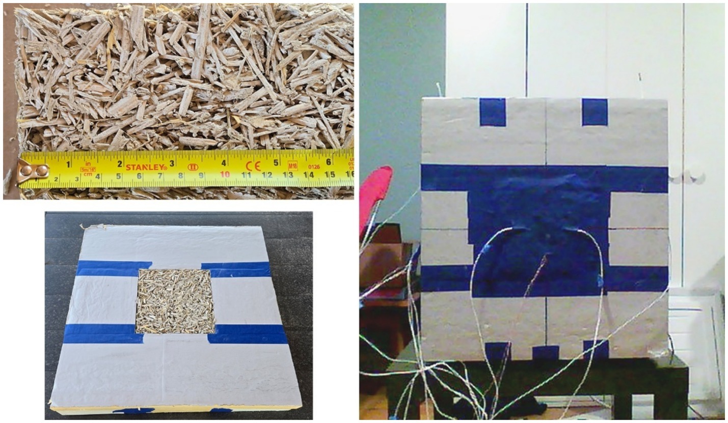
Figure 4. A hempcrete specimen representing the ZCMH mix, enclosed in guard insulation and set up for testing R-value with thermocouples and thin film heat flux sensors (Source: Author).
For the ZCMH, experimentation with binder mixes continued with a binder using a 1:2 ratio of PC to HL, with a final dry ratio of 1 part hurd, 0.5 part PC, and 1 part HL. Maintaining a higher quantity of HL was proposed to take advantage of lime’s CO2 uptake from the carbonation process, which reduces its embodied carbon by 30 to 50% (Arehart et al., 2020; Florentin et al., 2017; Pretot et al., 2014). When combined with the coarser hemp hurd, the new binder mix consolidated and cured well in test blocks, with increased porosity and reduced density versus prior experiments.
2.4 Program and architectural design for the ZCMH
At the beginning of the design process, the clients for the Zero Carbon Microhome—Habitat for Humanity of the Northern Flint Hills—charged the studio with developing a prototype home with a footprint less than 1,000 ft2 (93 m2) that would contain two bedrooms and two bathrooms, with enough space for a household of three people. The ‘microhome’ designation was intended to appeal to first-time homeowners, small families, and retirees that were priced out of the Manhattan, Kansas metro housing market. Prior iterations of the studio had built 3-bedroom homes in the size range of 1,200 to 1,400 ft2 (111 to 130 m2), and the smaller footprint of the ZCMH would further reduce construction costs and allow four units of the ZCMH to be built in a “cottage cluster” around a shared green space (Figure 5), developed through HHNFH’s community land trust. The final design of the ZCMH consisted of an open public zone in the middle of the house containing the kitchen, dining area, and living room, flanked by two winds of private space (bedrooms and bathrooms) in an 864 ft2 (80.3 m2) footprint (Figure 5). A generous front porch and a unified approach to structure and other building systems completed the design. Two small lots were purchased by HHNFH in Ogden, Kansas (within Manhattan’s metro area) where the cottage cluster of ZCMHs would be constructed.
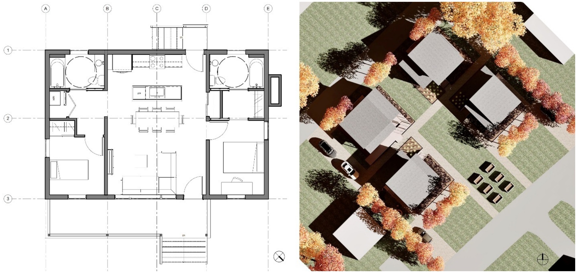
Figure 5. Floor plan (left) for the Zero Carbon Microhome, showing its two-bed, two bath layout. The site plan (right) shows the configuration of four units around a common space to create a cluster development for the community land trust (Source: Net Positive Studio, K-State).
2.5 Final integration strategies: structure, prefabrication, envelope, and building systems
The project team was already experienced with panelized prefab, and for this project the team decided to use a combination of modular (aka volumetric) and panelized prefab construction. The two private wings of the home would be built as 10-foot wide modules, while the 16-foot wide center bay would be panelized with a stick-framed roof from pre-cut members. Overall, the home’s footprint of 24×36 feet incorporates a standard framing layout. Panelizing the central bay allowed the height of the home to exceed the transport-imposed height limits of modules. The team initially assembled all components of the home’s envelope at the College of Architecture, Planning, and Design’s off-campus shop while site work was completed; the panels, stick-framed components, and modules were then disassembled and moved to the nearby site in Ogden.
Energy modeling was used early in the design development process to optimize the depth of hempcrete and hemp fiber insulation needed to attain the home’s net zero target. The maximum size of the ZCMH’s rooftop PV array was 5.39 kW DC, dictated by the utility. Using the online PVWatts analysis tool (accounting for the physical parameters of the system, typical losses, and power conversion efficiency) the maximum-sized array yielded an estimated output of 7,270 kWh/yr. This translates to an annual EUI target of 28.7 kBtu/ft2 or less for the house: a 30% reduction from the 40.9 kBtu/ft2 of the average Midwestern home (U.S. Department of Energy, Energy Information Administration, 2022). Optimization using energy modeling looked at several combinations of framing depth and spacing for the floor, ceiling, and exterior walls while also considering the cost and weight of framing materials, resulting in the following assemblies (Figure 6):
• Flooring framing with 2×10 wood members (9.25-inch depth) and hempcrete infill
• Wall framing with 2×8 wood members at 24-inch centers (7.25-inch depth) with hemp fiber batt infill
• Roof framing with 16-inch engineered wood TJIs on 24-inch centers in a ventilated roof assembly, with 14.5 inches available for hemp fiber batt infill
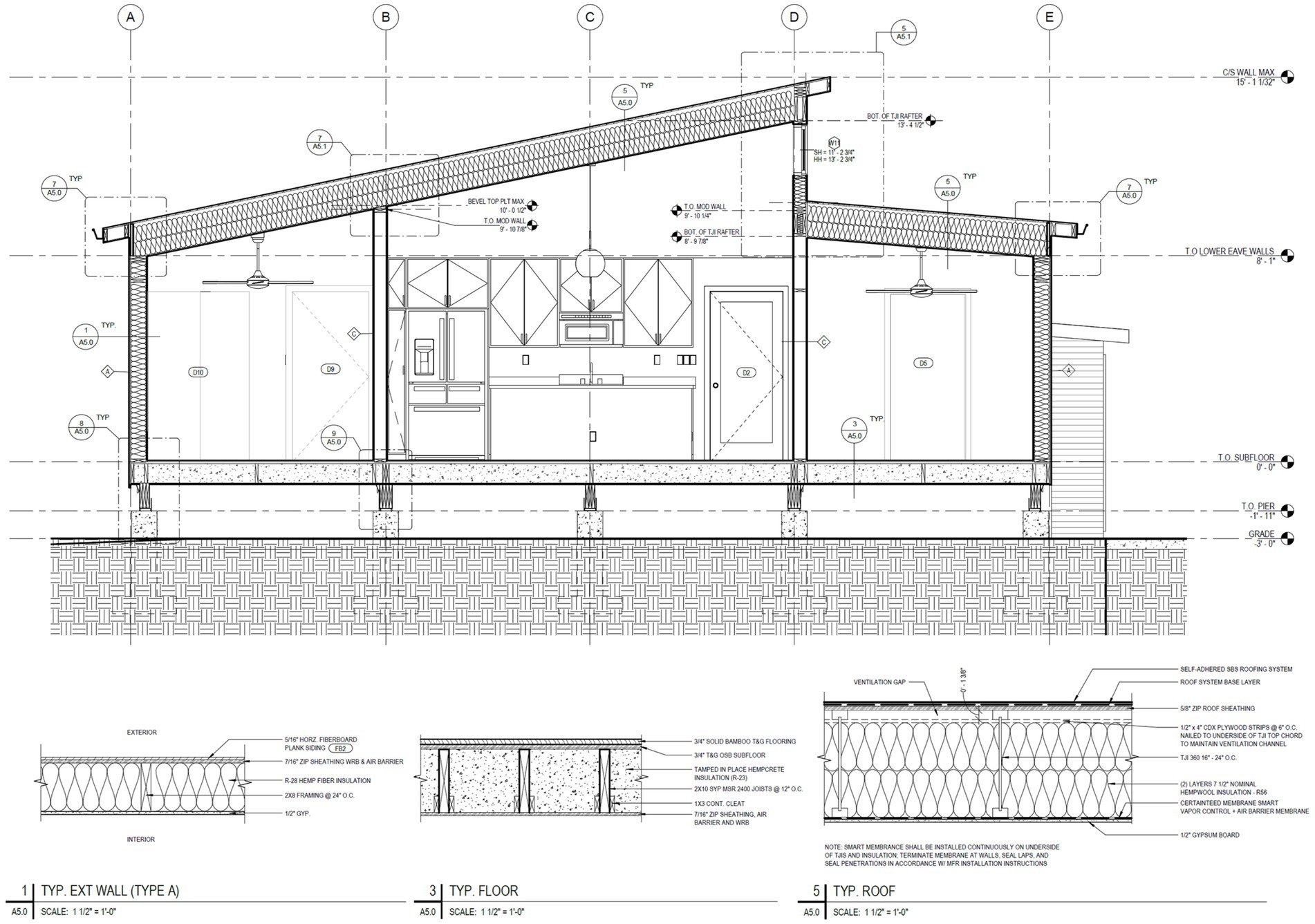
Figure 6. Section through the ZCMH with details for typical wall, floor, and roof types that incorporate hemp fiber and hempcrete insulation (Source: Net Positive Studio, K-State).
The dead load of the hempcrete was a crtitical design factor for the floor, increasing the typical 10 lbs/ft2 dead load to 25 lbs/ft2 for dead load (although finished density of the ZCMH ended up closer to 20 lbs/ft2); higher performance, mechanically stress rated (MSR) 2×10 lumber was used at 12-inch centers to create the floor with a 14.5in-wide horizontal plumbing chase running the length of the home. Weather resistant OSB sheathing formed the bottom of the floor deck. Wood cleats flank the bottom of the joists in each floor cavity, which help retain the hempcrete, while 0.75-inch weather resistant OSB subfloor completes the floor assembly on top. Below the hempcrete-infilled floor, five pressure-treated girders distribute loads to 12-inch diameter reinforced pier foundations; piers reduced concrete volume to 16% of a comparable slab-on-grade home.
The walls are framed with 2×8 members at 24-inch centers, with intermediate load bearing walls framed with 2x6s at 24-inch centers. The thicker wall construction provided the insulation depth needed to attain net zero energy performance, reduced thermal bridging through framing members, and allowed for the use of insulated headers to further reduce thermal bridging at structural connections. Weather resistant OSB sheathing would resist lateral loads while serving as the WRB and air barrier for the walls; per the project’s carbon reduction goals, no exterior foam insulation would be used. Wall insulation would be unfaced, as a vapor retarder is not required for the Manhattan climate.
For the roof of the house, 16-inch engineered wood TJIs were used to provide necessary insulation depth. Spacing at 24 inches improved the thermal performance of the ceiling, while the TJIs leave a 1.5-inch deep ventilation channel to allow the roof to be ventilated, with a continuous smart membrane for vapor and air control. Mechanical ventilation from the home’s ERV will control indoor humidity, and penetrations through the smart membrane will be minimized, together reducing the risk of condensation in the ceiling.
A detailed description of building systems is beyond the scope of this article, but an overview of strategies is presented here to add context to the energy analysis discussed hereafter. An important aspect of a “lean tech” home is to avoid the use of fossil-fuel-burning systems and appliances, allowing an all-electric home in which efficient electric appliances and systems can use renewable energy directly as it is available (commonly referred to as self-consumption), while credits from generated surplus energy can be used when solar energy cannot meet demand. The plumbing systems of the home will utilize EPA WaterSense fixtures to conserve water, and a 21 kW tankless electric water heater will provide hot water (the budget and available mechanical closet did not allow for a heat pump water heater). Ductless heat pump units will serve the home’s heating and cooling needs, in a three-zone configuration. The maximum design heating load for the home was determined to be 11,910 Btu/h (3,490 W) at a 99% winter design temperature of 9 °F (−12.8 °C), and maximum design cooling load was determined to be 6,379 Btu/h (1,870 W) at 1% summer design temperature of 97 °F (36.1 °C) using the ACCA Manual J method. All-LED electric lighting and Energy Star-certified appliances meeting affordability criteria were also specified. The final specification for the home’s photovoltaic systems consists of 14 roof-mounted bifacial polycrystalline modules with a combined array size of 5.32 kW, facing south-southeast (135° azimuth from north) with a tilt of 11.8° inclination. Like previous homes built by the studio, the PV array will have micro invertors installed on each module, which convert DC electricity to AC prior to delivering it to the controller and main electrical panel.
While early modeling used data from previous studio work and other sources, in order to accurately evaluate the energy performance and embodied carbon of the ZCMH, it was necessary to determine thermal properties and embodied carbon metrics that were as project-specific as possible.
2.6 Thermal and embodied carbon properties for hemp materials in the ZCMH
2.6.1 Hemp fiber insulation thermal and embodied carbon properties
The hemp fiber batts used in the ZCMH were sourced from Hempitecture, a U.S.-based manufacturer whose technical resources provided density, conductivity, and an LCA with embodied GHGe for the product (Hempitecture, 2025a,b), summarized in Table 1. A reference value from ASHRAE’s Handbook of Fundamentals was used for hemp fiber’s specific heat.
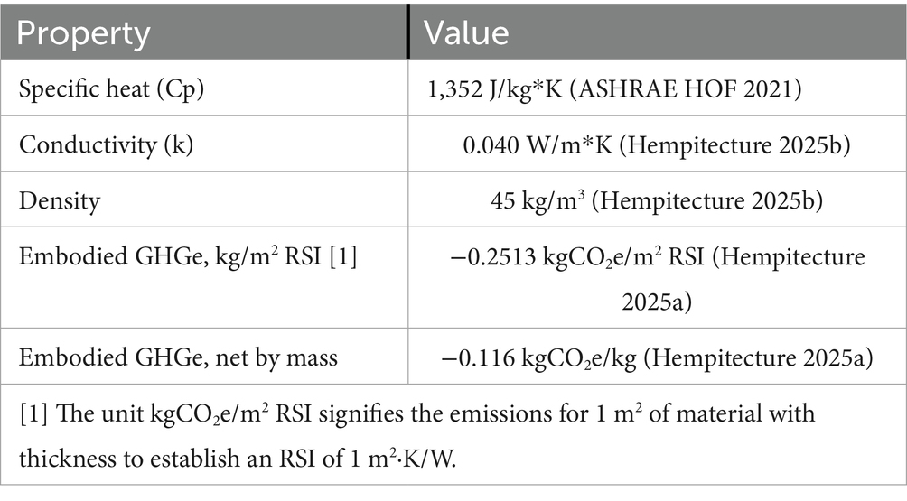
Table 1. Hemp fiber batt insulation thermal and GHGe properties.
2.6.2 Hempcrete thermal properties
The documented thermal properties for hempcrete vary widely, as shown by Sáez-Pérez et al. (2020) and others. To accurately represent the ZCMH hempcrete in energy simulation, testing and measurement of the actual hempcrete is necessary. The density of the ZCMH hempcrete mix was determined by simply weighing the dried test blocks, shown in Table 2. A second critical property is thermal conductivity (or thermal resistance), which must be determined using physical testing. The nature of hempcrete makes in-situ testing of full-scale building components, rather than small samples, especially important to understand the real-world performance of the material. One such standard in-situ testing method is ASTM 1155 (American Society for Testing and Materials, 2013), where heat flux sensors are used along with surface-mounted thermocouples to measure observed thermal resistance in the field, using the summation method to average for incidental environmental variability (Equation 1). Subsequent results are testing for convergence using Equation 2, which compares sequential periods of the test with duration ‘t’ to the overall results.
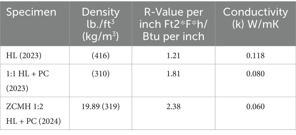
Table 2. Thermal properties and testing results of ZCMH hempcrete and select Previous mixes.
Methods from ASTM 1155 can also be used to evaluate medium-sized specimens, while one or both boundary conditions are maintained at a near-constant temperature to sustain steady state heat flow. While testing a medium-sized specimen does not strictly adhere to ASTM 1155, the testing set up can produce the same required in-situ testing conditions that establish a “subsection” of an envelope that “represent[s] uniform, non-varying thermal resistance” where sensor placement “represent[s] that subsection as a whole” with “no significant heat flow that bypasses the instrumentation in a manner that is uncharacteristic of where the instrumentation was placed,” while also using thermography to verify conditions (American Society for Testing and Materials, 2013). For this particular project, testing of a medium-sized specimen can provide preliminary data that precedes testing the final assembly in the field. For the ZCMH hempcrete and selected prior hempcretes, specimens measuring 7×7×3 inches (17.8×17.8×7.6 cm) were tested. The testing setup used an insulated chamber, maintained at 0 °F (−17.8 °C) with a precision digital controller on the cold side of the specimen, while the warm side of the specimen remained at ambient room temperature (generally around 68 °F or 20 °C) in an unoccupied, thermally stable environment. Specimens were guarded on their perimeter by polyisocyanurate foam insulation and masked with tape to prevent infiltration through the hempcrete specimen, while providing a smooth surface of ordinary emissivity (Figure 4). Specimens were conditioned for a minimum of 24 h to achieve steady state heat flow prior to data collection. Eight thermocouple channels, calibrated through ice-point calibration method, were used in pairs to measure air temperatures and surface temperatures on the warm side and cold side of the specimen. Thermocouple readings were logged using an Omega Data Acquisition Module (OMB-DAQ-2416-4AO) and surface-mounted junctions were attached with foil tape and then masked with thin opaque tape. Heat flux readings were collected using Omega HFS-4 thin film heat flux sensors on each side of the specimen; the heat flux sensors, with sensing areas of 1 cm2 each, were attached with a thin layer of thermal putty and masked with thin opaque tape. Heat flux sensor readings were collected with a Fluxteq FluxDAQ data acquisition module, with 1.5 Hz samples synchronized with the thermocouple logging, while thermography evaluated thermal uniformity at measurement sites (Figure 7).
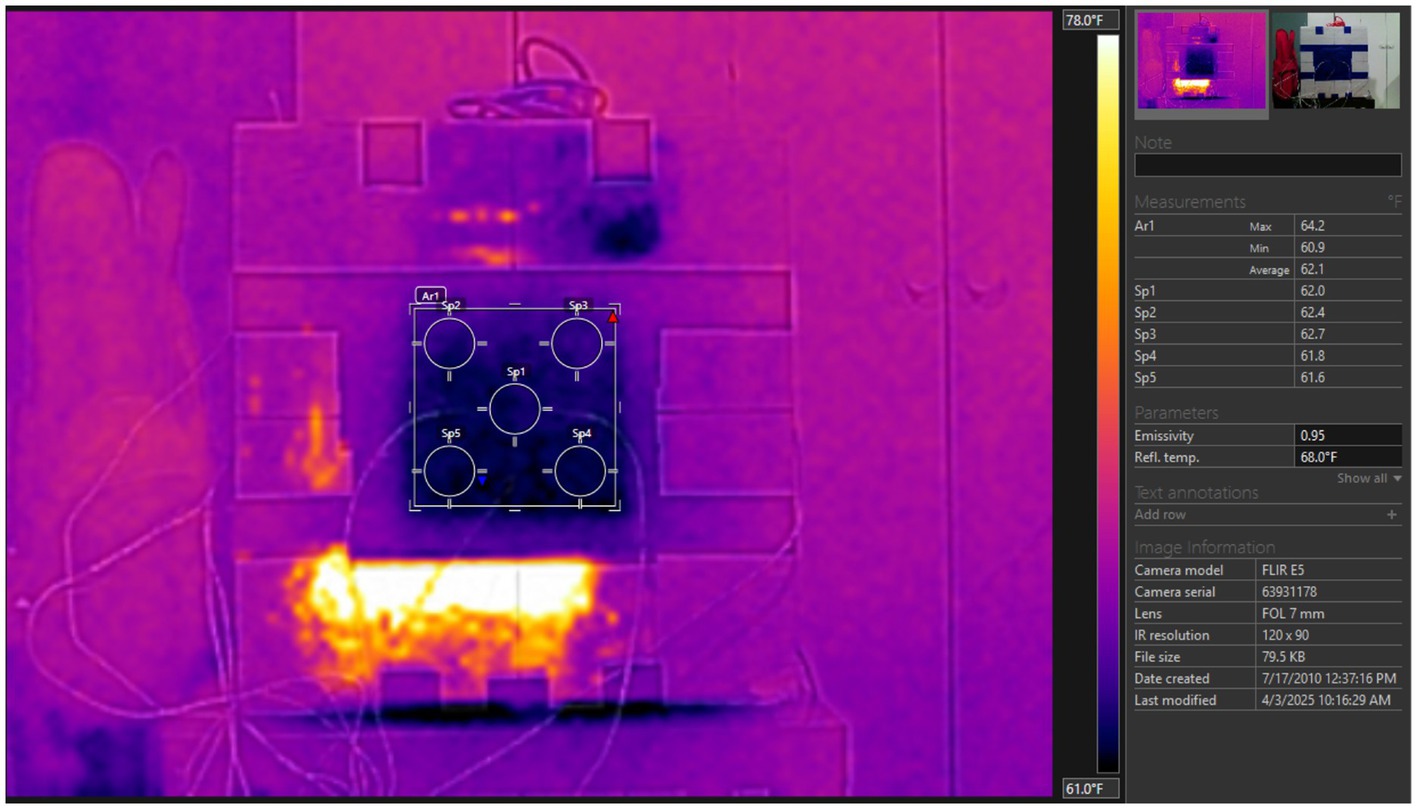
Figure 7. Thermography of the test setup, showing point and area-averaged surface temperatures of the specimen at center. Warm and cool blotches on the guard insulation are incidental thermal reflections on the insulation’s facing (Source: Author).
Another important thermal property of hempcrete is its specific heat. As a composite solid, the specific heat of hempcrete may be determined using the Rule of Mixtures, using a mass-based weighted average of the specific heats of its components to determine a composite specific heat. Importantly, the mass and specific heats of resultant cured binder components must be used to determine specific heat, rather than initial components, because curing involves a chemical reaction. For the mix ratio used in the ZCMH, a specific heat of 1,600 J/kg*K was assumed for the hemp hurd (Nováková, 2018). The mass change in the binder is more complex; while the specific chemical reactions are beyond the scope of this article, they are simplified here in order to accurately determine specific heat. While reacting with water, ordinary portland cement’s components go through the process of hydration to produce the constituent components of set cement; assuming a water-to-cement ratio of 0.45 and typical degrees of hydration, the mass of cement will increase 23% as water becomes chemically bound to the final cement components (Chuosavasdi et al., 2016). With some additional water and water gels remaining trapped in the voids and pores of the cement, the final mass of the cured Portland cement is estimated to be 1.25 times its original dry mass. Hydrated lime is composed primarily of calcium hydroxide, Ca(OH)2, with a molar mass of 74.093 g/mol. When lime cures, the calcium hydroxide undergoes the process of carbonation as it combines with free CO2 from the environment, producing calcium carbonate, CaCO3, whose molar mass is 100.0869 g/mol, increasing mass by 35.1%. As noted in Arehart et al. (2020) not all Ca(OH)2 will go through carbonation. Assuming a carbonation rate of 0.75, the cured lime binder component will be 1.263 times its original mass.
2.6.3 Hempcrete embodied carbon
Determining the embodied carbon in the ZCMH’s hempcrete follows a similar process used for specific heat, utilizing mass-based weighting according to the rule of mixtures. Because GHGe emissions are an input to the hempcrete mix, rather than a property of the resultant mixture, the initial dry ratios were used, along with water (Table 7). There were no available life cycle assessments (LCAs) for the specific hemp hurd, Portland cement, and hydrated lime used in the ZCMH, so reference values from published LCAs were used: hemp hurd and hydrated lime were taken from Arehart et al. (2020), while Portland cement is from the ICE Cement, Mortar, and Conc. Model v1.1, all shown in Table 7. Note that these values are not complete LCAs but rather cover processes A1-A3 in the Production Stage, and B1 of the Use Stage in the systems boundaries defined by EN 15978. Comparing the LCA from Arehart et al. (2020) to two other commonly cited LCAs, the initial and stored emissions of hemp hurd and hydrated lime differ but the net embodied emissions are very similar: hurd at −1.715 kgCO2e/kg and lime at 0.73 kgCO2e/kg in Florentin et al. (2017), and hurd at −1.7 kgCO2e/kg and lime at 0.85 kgCO2e/kg in Pretot et al. (2014). Water was added to the ZCMH hempcrete mix at a ratio of 1 part dry hempcrete mix (hurd and binder combined) to 0.8 parts water by mass; as discussed earlier, a certain amount of this water is converted chemically when the binder cures, while the remainder of the water evaporates out while the hempcrete dries. To determine the embodied GHGe of the resultant cured hempcrete mix, a mass-weighted calculation using the ratios of the initial components (including water) and their emissions was completed. Cured, these components together would yield 0.642 of their original mass (i.e., 1 kg of mix would yield 0.642 kg) based on factors discussed already in the determination of specific heat. A final calculation converts the mass-weighted GHGe to units per 1.0 kg.
2.7 Analysis tools and methods
2.7.1 Energy analysis
Annual energy simulations were used throughout the design process to inform decisions, first with material properties from prior testing or from software libraries. The final simulation, presented in Section 3.2, used updated thermal properties for hemp fiber insulation, presented in Table 3. Simulations were completed using ClimateStudio, a plug in for the 3D CAD program Rhino, which uses EnergyPlus v9.1.0 as its analysis engine. For the purposes of this article, modeling compares the ZCMH to the average midwestern detached home’s energy consumption characteristics (U.S. Department of Energy, Energy Information Administration, 2022), a 1,600 ft2 reference home using IRC 2018 criteria, and a previously completed 3-bed, 2-bath, 1,203 ft2 home designed by the studio (“Ogden #1,” shown also in Figure 2) in which the home’s foam-based insulation strategy is represented. The inclusion of the 2018 IRC home represents the typical affordable single family homes now being built in the Midwest; those familiar with residential efficiency codes understand this is not necessarily a high bar for comparison.
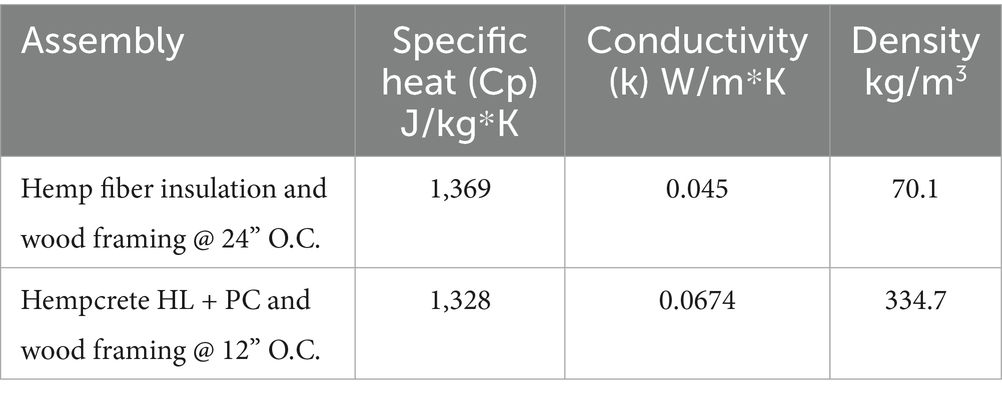
Table 3. Energy analysis assembly properties for hemp fiber and hempcrete.
A summary of simulation parameters are shown in Tables 4 and 5. Equipment and lighting loads were based on products specified for the home. Heating and cooling loads were simulated as ideal loads, with simple coefficients of performance for the proposed equipment used to determine HVAC energy used; the heating season efficiency of air-source heat pumps was derated using the Department of Energy’s heatcalc.xls. Water heating energy usage was based on flow rates for WaterSense fixtures, demand estimates from LEED v4.1 Water Reduction Calculator, and electricity consumption based on a ∆T of 68 °F. Water heating was included in the equipment category in the results.
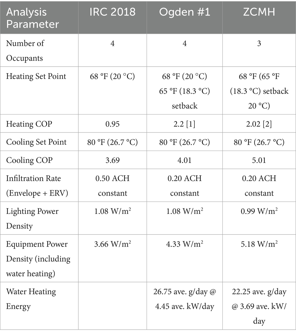
Table 4. Energy analysis simulation parameters and inputs.
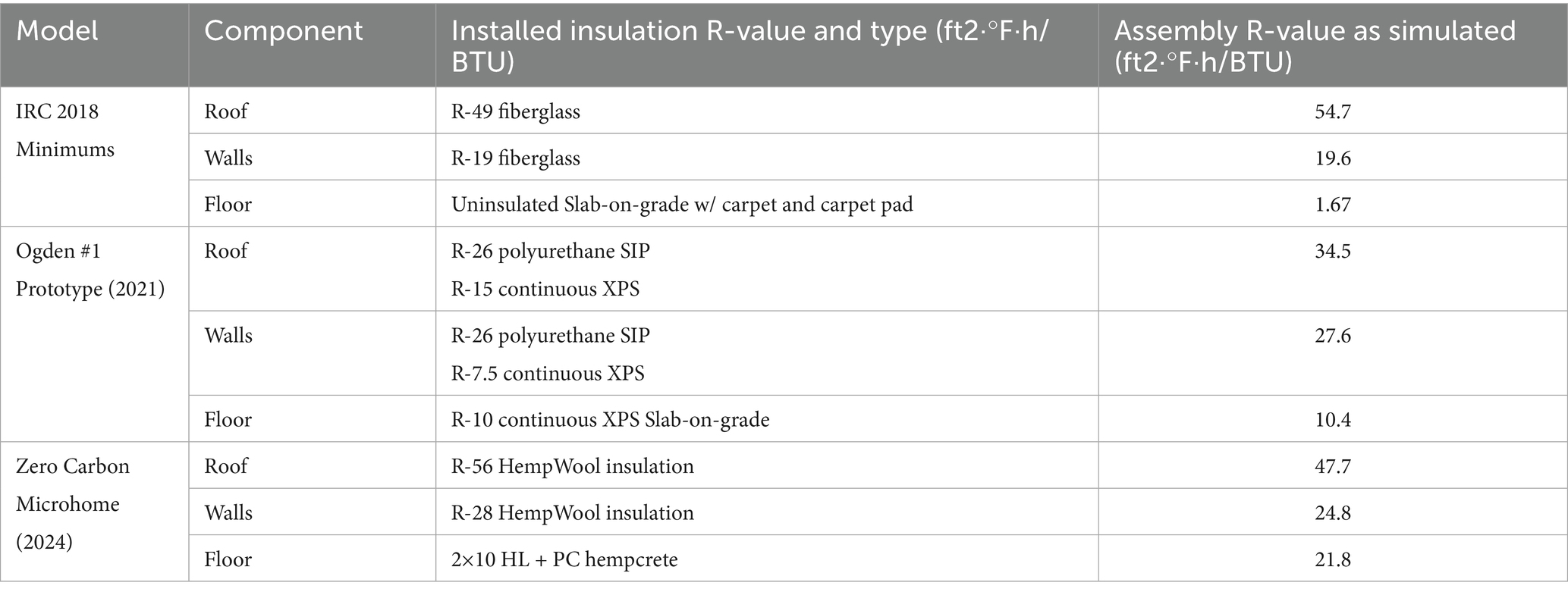
Table 5. Energy analysis envelope inputs.
2.7.2 Carbon assessment
Contemporary whole-building carbon analysis accounts for greenhouse gas emissions (GHGe) from three categories: embodied GHGe, operations GHGe, and transport GHGe. The carbon assessment of the ZCMH focused on embodied and operations GHGe. Standards are still being developed for whole-building carbon, as of 2025, so this assessment will draw from currently proposed standards employing a “carbon balance” method that totals embodied and operations GHGe over a period of time.
Operations GHGe consists of direct and indirect emissions from lighting, equipment, heating, and cooling. Embodied carbon in the building’s materials is determined using a combination of material and product life cycle assessments (LCAs) within an analysis tool to produce an assessment of embodied carbon in the building. Today, embodied carbon analysis is typically limited to the more carbon-intensive structure and enclosure (S&E) of a building, where concrete, steel, aluminum, and other envelope components are typically the largest contributors to embodied GHGe. Fixtures, MEP systems, furniture, casework, and similar items are not typically part of an S&E calculation. LEED v5 proposes to add an additional 50% of the base S&E GHGe to account for uncounted GHGe beyond the structure and enclosure, with GHGe from future renovations and replacements added at 10-year cycles as 25% of the initial S&E carbon (United States Green Building Council (USGBC), 2025).
For embodied GHGe, the software BEAM v1.1 was used to evaluate the structure and enclosure of the ZCMH. Like similar tools, BEAM contains a library of LCA information which was used for most components in the analysis, with the exception of the project’s hempcrete and hemp insulation, which used specific values listed in Tables 1 and 7. For the ZCMH, the USGBC factors for non-S&E and renovation embodied GHGe were added to the base S&E embodied GHGe from BEAM to present a complete carbon balance. A 15-year renovation cycle was used in place of USGBC’s proposed 10-year cycle, which is more appropriate for single family homes.
Regarding biogenically stored (sequestered) carbon, hemp is considered to store biogenic carbon in the short term, as it may be grown continuously as a crop, contributing to embodied GHGe that are less than zero (carbon negative). Although wood has the potential for biogenic carbon storage, current consensus indicates that U.S. lumber should not be assigned biogenic carbon in carbon analysis. For this reason only biogenic carbon storage for hemp was accounted for in this analysis, and storage is omitted for wood.
2.8 Construction process
2.8.1 Prefab construction
Building on prior experience with prefab construction, the Net Positive Studio incorporated prefab construction methods into the design and construction of the ZCMH. A comprehensive BIM model was used for design, documentation, and shop drawings to guide the team through the construction of prefab components (Figure 8). As discussed earlier, the ZCMH would use a hybrid approach in which the outer bays of the home would be built as three-dimensional modules, the floors and wall in between as panels, and the TJI roof as individual pre-cut components. The project team began with the seven floor panels, framing them upside down to attach the WRB sheathing. The seven panels were then moved outside, where they were blocked into a level platform to prepare for hempcrete placement. After placing the hempcrete, the team assembled exterior and interior wall panels in the shop while the hempcrete dried.
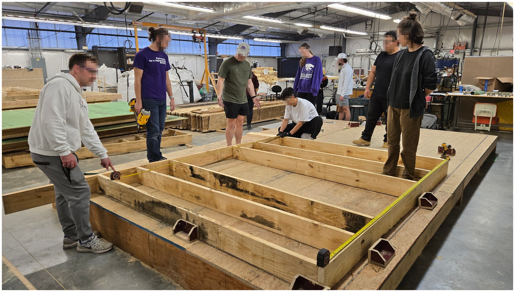
Figure 8. Prefab construction process in the shop; students in the studio are framing a wall panel (Source: Author).
2.8.2 Hempcrete process
Once the platform was established outside, hempcrete work commenced (Figure 9). The team used two mortar mixers with 7 ft 3 capacity, which had a fixed drum and rotating paddles rather than the rotating drum of a cement mixer. During mixing of dry components, all team members wore personal protective equipment: goggles, N95 respirators, and chemically resistant rubber gloves. The working mix ratio for the hempcrete, by weight, was:
• 2 parts hemp hurd (50 lbs)
• 1 part Portland cement (25 lbs)
• 2 parts pressure-hydrated type-S lime (50 lbs)
• 2 parts cold water (13 gal +/− 1 gal, adjusted to achieve proper mix consistency)
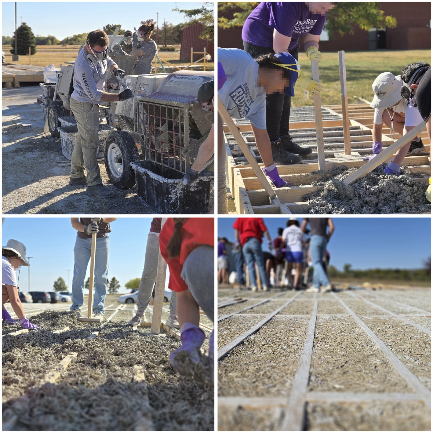
Figure 9. The hempcrete process, mixing and placing hempcrete in the prefabricated floor platform (Source: Author).
The team metered water using an inline digital water meter connected to the water supply, which could track water volume to the nearest 1/10 gallon. The quantity of water required adjustment during the mixing of each batch, due to moisture and dust content variability in the air-dried hemp hurd. Dry ingredients were measured using an industrial scale. The successful mixing procedure practiced by the team followed this sequence:
1. Add half of the hemp hurd to the mixer drum (25 lbs).
2. Spray the mixture to achieve dampness (but not allowing for free water) in order to reduce dusting, while the paddles rotate.
3. Slowly add the cement and lime binder (75 lbs) while the paddles rotate, spraying half of the water into the mix (approx. 7.5 gal).
4. Add the remaining half of the hemp hurd (25 lbs) to the mixer while spraying the remainder (approx. 7.5 gal) of the water.
5. Allow the mix to rotate in the drum, ensuring the hempcrete reaches a consistency with which it “falls” from the paddles as the mixer rotates.
6. Dump the mix into carrying bins, allowing it to sit for 10 or so minutes to “rest” which allows water to propagate throughout the wet hempcrete. The hempcrete, at this point, should not be shedding liquid water but should rather appear sticky. A simple consolidation test is to grab a handful of hempcrete and compress it into a snowball (Figure 16); if the snowball can be tossed up and down without breaking, the hempcrete can consolidate well. It is also normal for the snowball to break apart if a finger pressed into it; this indicates the hempcrete has not been overly saturated with water or binder. If the hempcrete looks like mud, there is likely too much binder in it.
When the hempcrete was ready to be placed, it was moved by hand into the floor platforms and placed one cavity at a time, with light tamping to ensure it filled the cavities completely (Figure 9). A 14.5-inch horizontal chase in the floor framing was left open of hempcrete in order for plumbing to run the length of the house. While hempcrete could be used to insulate around the roughed-in plumbing, it was the choice of the project team to preserve future serviceability of the plumbing systems by specifying that hemp fiber fill the chase after rough-in. Hempcrete work proceeded over the course of nine partial work days, limited by class time, and took approximately 348 person-hours to complete. Approximately 551 ft3 of hempcrete was placed, with a finished weight of approximately 10,970 lbs, using (70) 45 lb. bags of lime and (19) 92.6 lbs bags of Portland cement, including some spillage and waste.
2.8.3 Module assembly and next steps
With the hempcrete dried, the team decked over the hempcrete-infilled platform with 0.75-inch tongue-and-groove OSB subfloor. Wall panels were moved outside and assembled onto the floor platform (Figure 10). Walls that enclosed the prefab modules were attached permanently, according to construction plans and specifications, while the panelized walls in the middle section and the upper clerestory were erected temporarily. These walls in the middle section of the house, along with the roof in that area, were taken down when the project was moved. Construction Technology students from Manhattan Area Technical College worked with construction trades students from the Home Builders Institute at Ft. Riley to assemble the enclosure. With the installation of roof rim boards, TJI roof joists, and roof sheathing, the weather-enclosed structure was completed in December of 2024. The project was moved to the site in Ogden, Kansas in April of 2025 where it was dried in. It is currently awaiting further insulation, finishes, and systems installation; the remainder of the construction process will use familiar residential construction materials and methods to complete the house.
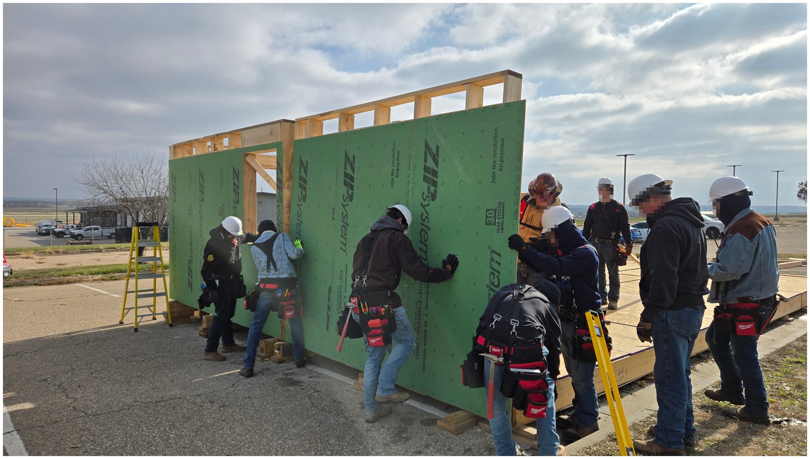
Figure 10. Students from Manhattan Area Technical College (MATC) erect wall panels at the K-State College of Architecture, Planning, and Design’s off campus shop (Source: Author).
3 Results
3.1 ZCMH hempcrete thermal properties
Observed thermal conductivity of three hempcrete specimens is shown in Table 2: the first specimen from 2023 using hydrated lime binder discussed prior (HL), the second specimen also from 2023, which used a 50/50 hydrated lime and Portland cement binder (1:1 HL + PC), and the third specimen composed of the mix used in the ZCMH with a ratio of 1:2 PC to HL in the binder. After processing the data from thermal testing using Equation 1, observed R-value was determined. Conductivity was then calculated by dividing the thickness of the specimen by the observed R-value. Two tests were done for the ZCMH hempcrete and their convergence plots, using Equation 2, are shown in Figure 11. The results of testing (Table 2) show an improvement in thermal conductivity with each hempcrete mix, with the ZCMH hempcrete attaining a conductivity of 0.060 W/mK, which would be among the lowest conductivities cited by Sáez-Pérez et al. (2020).
Specific heat for the ZCMH was calculated according to the Rule of Mixtures; Table 6 shows the initial dry mass ratios, the resultant cured mass ratios, and the specific heat of the hempcrete components. Using the resultant cured masses, the specific heat of the hempcrete used in the ZCMH is 1,285 J/kg*K, in the upper range of hempcrete according to Sáez-Pérez et al. (2020).
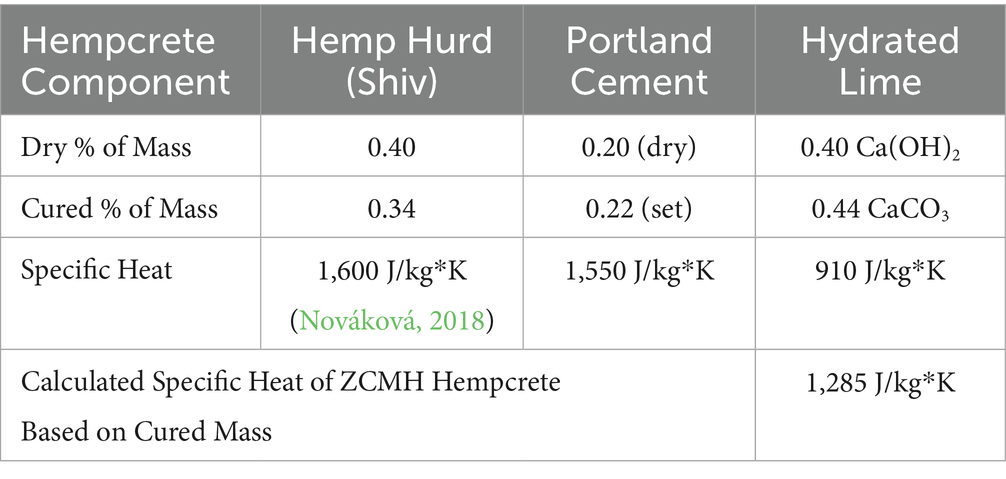
Table 6. Specific heat results for ZCMH hempcrete.
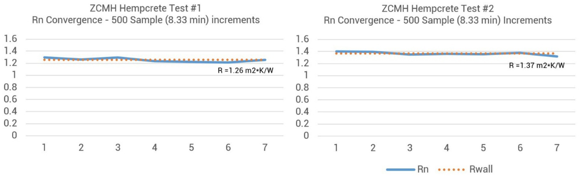
Figure 11. Convergence plots for two tests measuring thermal resistance of the ZCMH hempcrete. Note these are R-values for the 3-inch specimen, rather than conductivity (k) (Source: Author).
3.2 ZCMH energy analysis
In order to proceed with energy analysis, custom EnergyPlus materials were required to represent composite thermal properties for the hemp fiber insulated walls and the hempcrete floors. Using the method for area-weighted thermal properties from ASHRAE’s Handbook of Fundamentals, the composite properties in Table 4 were determined and used in energy modeling.
In order to control for floor area, the energy analysis results can be compared according to Energy Use Intensity (EUI), given in annual energy used per unit floor area. Total EUIs and a breakdown of four primary categories of energy use (lighting, equipment, heating, and cooling) are shown in Figure 12, which includes the final energy simulation results for the ZCMH. The average midwestern home has the highest EUI, while the EUI is barely improved at all in the 2018 IRC simulation. The ZCMH’s EUI is slightly increased from the EUI of the Ogden Prototype #1. Total estimated annual energy used for the ZCMH is 5,953 kWh; the estimated output of the specified 5.32 kW photovoltaic array is 7,176 kW annually, ensuring a high likelihood that the house will offset its site energy use with renewable energy.
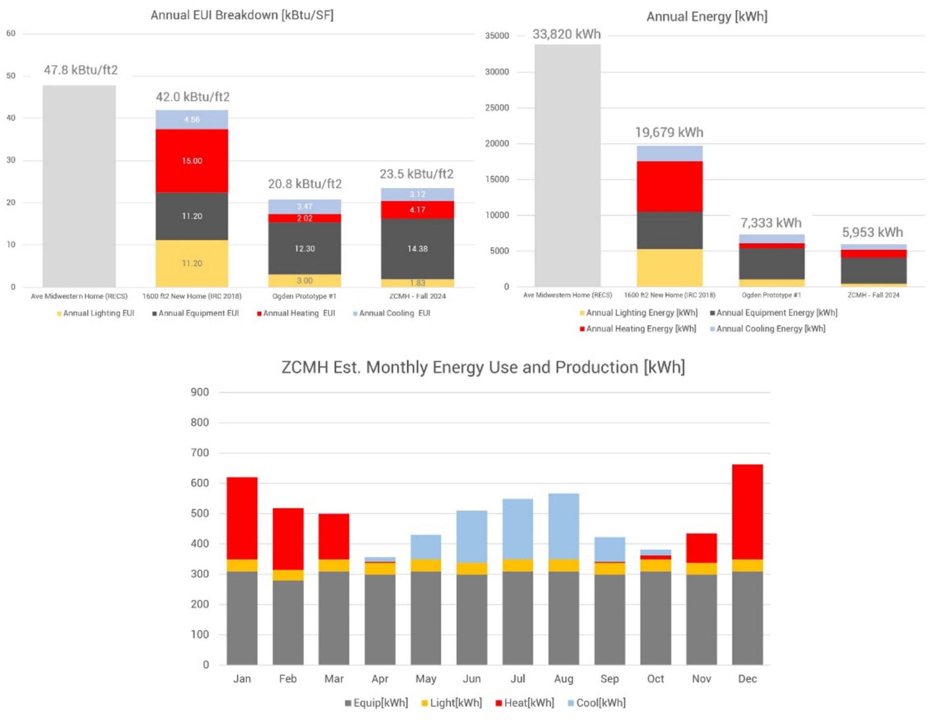
Figure 12. Energy analysis results comparing the ZCMH to the Ogden # Prototype (shown in Figure 2), a 1,600 ft2 new home built to IRC 2018 prescriptive requirements, and the average midwestern home (Source: Author).
3.3 Embodied carbon of the ZCMH’s hempcrete
Following the process described in 2.6.3 and using the values in Table 7, the embodied GHGHe of the ZCMH’s hempcrete is estimated to be -0.190 kgCO2e/kg. While carbon negative, this final result is lower than anticipated, based on the range of −0.3 to −1.0 kgCO2e/kg cited in Sáez-Pérez et al. (2020). As noted by previous studies, the carbon contributed by the binder is a primary factor in embodied GHGe, and some studies may overestimate uptake from lime carbonation (Arehart et al., 2020; Sáez-Pérez et al., 2020). Using water from a municipal water source also adds significant embodied energy; non-U.S. readers may be surprised that potable water would be used this way, but using low-GHGe groundwater was not feasible for the project.
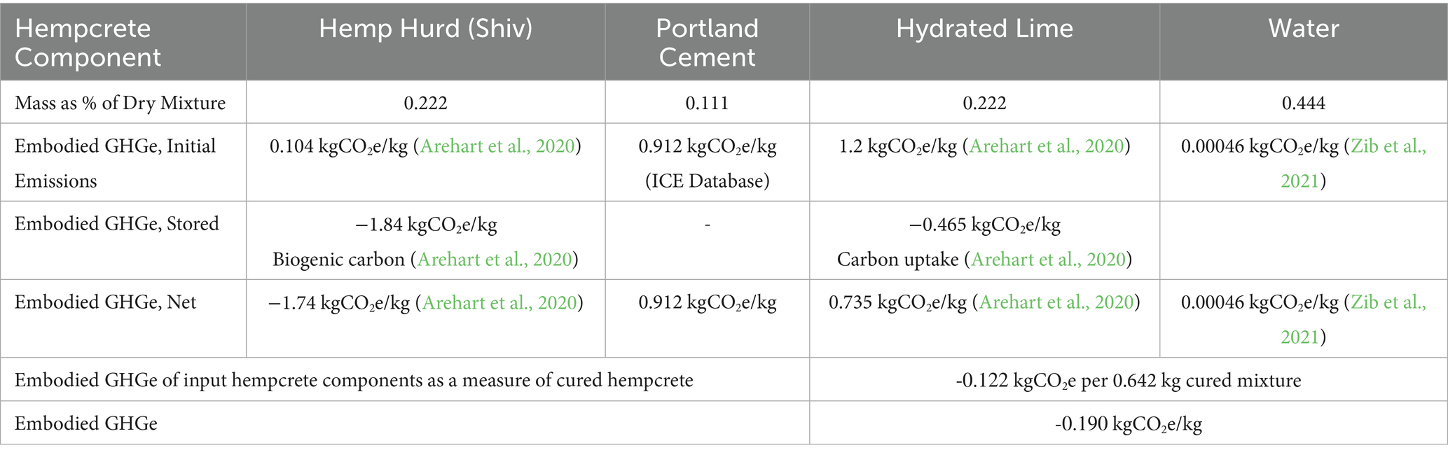
Table 7. Embodied GHGe of Hempcrete and Components.
3.4 Carbon assessment and carbon balance of the ZCMH
To present the carbon balance of the ZCMH, first it is important to understand how operations and embodied GHGe contribute to the carbon balance of a typical new home. For operations carbon, the average midwestern home’s 33,820 kWh (115,399 Btu) of annual energy would generate the annual GHGe of 9,131 kgCO2e, assuming a mix of 35% KS-based electricity and 65% KS-based natural gas (using the EPA’s TargetFinder website). For embodied carbon, the S&E GHGe of conventional construction methods are expectedly high while varying greatly; for the sake of discussion, a small 1,600 ft2 home could easily have a 65,000 kgCO2e embodied GHGe at its outset, plus additional GHGe for non S&E GHGe and future renovations. Embodied and annual operations GHGe can be graphed in a cumulative carbon balance, as shown in Figure 15. By year 40, this home would be responsible for over 500,000 kg of GHGe.
The net embodied S&E GHGe for the ZCMH are shown in Figure 14, at 4,484 kgCO2e. It may seem like 4,484 kgCO2e is still a large number, but consider it is just 7% of the 65,000 kgCO2e for the hypothetical new home mentioned previously. An additional 2,242 kgCO2e of GHGe for non-S&E emissions (50% of net S&E GHGe) and 1,121 kgCO2e of GHGe (25% of net S&E GHGe) for future renovations at 15-year increments were added to the ZCMH’s and typical new home’s carbon balance to complete the projections shown in Figure 15. Regarding operations GHGe for the ZCMH, net metering will allow the home to use electricity from the grid (positive GHGe emissions), use emissions-free electricity directly from the PV system (self consumption), and send surplus emissions-free electricity back to the grid for credits that accumulate on a 12-month basis. With some additional capacity from the home’s PV array (see energy analysis results in 3.2), it is estimated that the home will have a small annual surplus of 1,222 kWh of energy; in LEED v5 and other proposed zero carbon systems, this surplus energy (metered at the site) is considered a carbon offset (negative GHGe) in the building’s carbon balance. Thus the 1,222 kWh of surplus amounts to an offset of −416 kgGHGe, based on 763 lbsCO2e/MW for current Kansas power (U.S. Department of Energy, Energy Information Administration, 2024a,b). The projected carbon balance, shown in Figure 15, shows the ZCMH attaining net zero carbon by year 19.
3.5 Evaluating the hempcrete curing process
The students and the author placed hempcrete for 12 days (10/2/2025 to 10/16/2025), after which the platform was left for 36 days to reach adequate curing: a process where water would need to evaporate from the hemp and cement binder components, while the lime binder components required ambient CO2. The team covered the platform with a tarp only during periods of rain, after which it was uncovered to resume curing. During curing, moisture measurements were taken with a two-pin resistance moisture meter, collecting data at three conditions: the exposed surface of the hempcrete, at adjacent wood framing, and on the underside of the platform roughly centered on a framing cavity. Three different locations (A, B, and C) on the platform were measured in this manner, with the results shown in Figure 13; location A’s sheathing was not measured because it was too close to the ground to access for proper measurement.
4 Discussion
The Zero Carbon Microhome offers several points of discussion regarding the use and performance of hemp and hempcrete, as well as the general approach an affordable home might take to go beyond net zero energy to achieve net zero carbon.
4.1 Successes of the ZCMH’s hempcrete and further research
Looking specifically at the HL + PC hempcrete used in the ZCMH, the mix remained lighter-weight than hempcrete using HL-only binders, making it conducive for an application in a raised floor. Secondly, the larger hemp hurd fibers improved the hempcrete’s porosity, contributing to the improved thermal resistance and possibly improved curing. The carbon analysis results in Table 7 show a modest increase in embodied GHGe by introducing some PC in place of HL in the binder, but since the PC is only 11% of the hempcrete, it’s impact is relatively small: only increasing embodied GHGe by 2.6% while the PC improves thermal resistance and curing.
The 36 days of moisture readings (Figure 13) showed a strong drying trend for the hempcrete in the project’s floors, evidenced by the three locations becoming progressively drier, all reaching a similar moisture content below 10%. Readings from wood framing and sheathing showed these materials taking up some moisture from the hempcrete and from the environment but returning to their original moisture level.
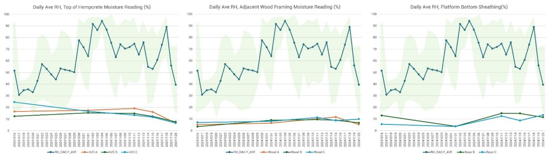
Figure 13. Plots of the hempcrete’s drying progress over 36 days, measured with a two-pin moisture meter and compared with daily average relative humidity from the NOAA U.S. Climate Reference Network. Three points on the floor platform had readings taken at the top of the hempcrete surface, at an adjacent floor joist, and on the sheathing below the platform (Source: Author).
The mechanical properties of HL + PC hempcrete were beyond the scope of this article, but analysis and comparison versus a range of accessible binders (including proprietary binders) should be studied in the future. Further study may also be done on understanding the variability of water in the mixes, and how it affects the characteristics of the finished hempcrete.
4.2 Comparing energy performance of the ZCMH versus other homes
Comparing the Ogden #1 home and the ZCMH’s energy results, the overall EUI moves upward from 20.8 to 23.5 kBtu/ft2 per year, an increase of 13%. Examining the breakdown of energy in Figure 12, the contribution of heating and cooling energy to EUI increases by about 30% for the ZCMH. Replacing the high R-value, continuous, closed-cell insulation in Ogden #1 with modest performing insulation in the ZCMH explains part of this change in performance. In the case of the 2018 IRC home, ground contact by way of the uninsulated slab moderates cooling loads while leaving heating costs elevated, which also run higher due to conventional gas heating. Fully insulating the slab, as in the Ogden #1 project, allows the slab to more effectively perform as thermal mass year-round, while increased thermal resistance in the overall envelope and the high-efficiency heat pump HVAC lead to additional reductions in energy use. The elevated floor in the ZCMH leads to an increase in heat losses in the winter, due to its exposure, although the hempcrete provides some moderate thermal mass.
Overall, the 30% increase in heating and cooling EUI energy between the Ogden #1 prototype and the ZCMH is marginal, compared to energy reductions made versus the IRC 2018 home and the average midwestern home (Figure 12). With a single 380 W PV module producing an estimated 519 kWh annually, such a slight dip in performance can be offset with additional PV capacity to maintain net zero energy performance. It should also be noted that part of the EUI increase comes from the energy “penalty” impacting small homes with respect to equipment energy, which is unrelated to hemp or hempcrete; small homes need to have the same electricity-consuming appliances and equipment as a larger home in a smaller footprint, which can push EUI upwards.
4.3 Comparing the carbon balance of the ZCMH versus a typical new home
The usual contributors to embodied GHGe, particularly in the concrete-intensive foundations and foam-intensive envelope, are moderated due to the approaches employed by the ZCMH. The carbon-negative contributions of hempcrete in the floors, hemp fiber insulation in the walls and roof, and solid bamboo in the finish floor come together to offset a significant amount of embodied GHGe in the remainder of the S&E components (Figure 14).
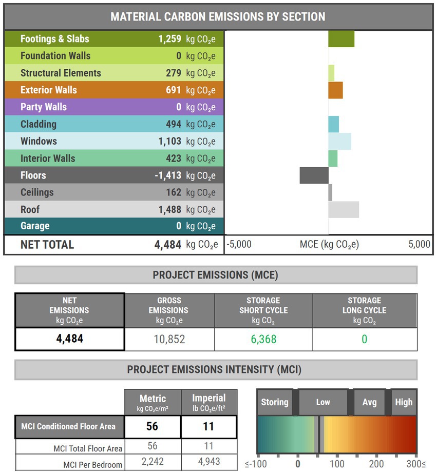
Figure 14. BEAM embodied carbon analysis results, showing different categories in the structure, envelope, and finishes of the house contributing to net embodied GHGe of 4,484 kgCO2e (Source: Author).
The ZCMH serves as an example of the value of reducing both embodied carbon and operations carbon, rather than sacrificing one of these imperatives to achieve the other. Operations carbon cannot be understated for its role in contributing to GHGe; as shown in the carbon balance in Figure 15, operations carbon will dominate the carbon balance of an inefficient house over time, regardless of whether the home has a low or high embodied carbon footprint.
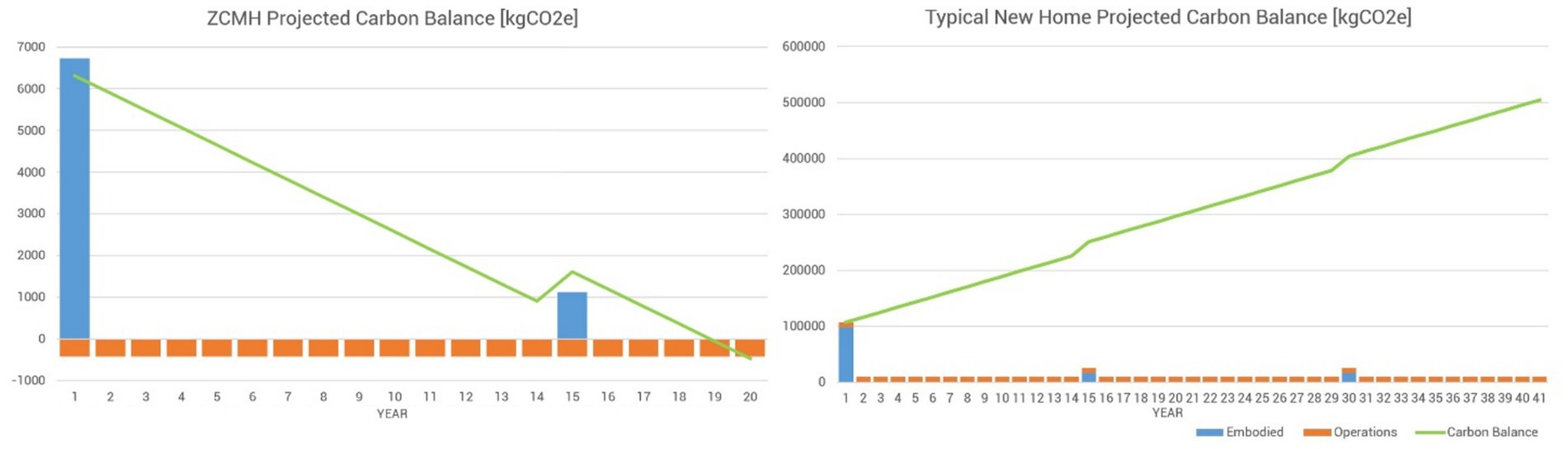
Figure 15. Carbon balance for the ZCMH (left) with initial embodied GHGe, additional embodied GHGe from renovation at year 15, and annual offsets from surplus renewable energy produced; cumulatively, it will achieve net zero carbon by year 19. The carbon balance for a typical new home (right) surpasses 500,000 kgCO2e by year 40 (Source: Author).
Improvements and revisions to LCA information can have significant impacts on carbon analysis. During the ZCMH project, the real LCA data for the specified hemp fiber was twice as high in embodied GHGe than the non-U.S. market placeholder product used in early carbon analysis, shifting the embodied GHGe of the whole project drastically upward. Meanwhile, new LCAs for ordinary construction materials like drywall went downwards, with improvements to these materials’ carbon footprints recognized in an update of the analysis software’s library. In the future, further reductions in GHGe within the materials industry (including in hemp-based products) will make their way into updated LCAs, while the accuracy and decision-making potential for carbon analysis tools continues to improve.
In discussing the carbon analysis, finally, it may be observed that operational water has been left out. At this time, many U.S.-focused zero carbon certification systems and resources do not include operational water (among them LEED Zero Carbon, programs from the International Living Future Institute, and the Whole Building Design Guide). Potable water does indeed carry a carbon footprint (see Section 3.3); in the ZCMH, one solution to netting out the carbon from potable water would be to increase the size of the PV array to produce more renewable energy offsets. However, under the local utilitie’s, net metering policies, the imposed size limits to the PV array would make this option impossible. Future recognition of the role of potable water in the carbon balance is critical; investment to make potable water net zero carbon with renewable energy at the utility level seems to be most logical.
4.4 Applications for hempcrete in floor assemblies
The ZCMH shows hempcrete has a strong integration and performance potential for elevated wood-framed floors, which are usually a challenge to insulate in projects such as manufactured housing. The floor of the ZCMH is somewhat like an earth-integrated floor slab, offering functional thermal mass that can perform as a thermal buffer in a mixed climate like Kansas, as indicated by energy analysis. The elevated hempcrete floor was also relatively easy to construct, where hempcrete placement did not involve shuttering boards or the anxiety of a vertical wall failure. The hempcrete seemed to dry quite well when incorporated in a floor, as long as it could be protected from the rain; subsequent rain and snow that fell on the weather-resistant OSB subfloor during assembly of the enclosure did not seem to penetrate the hempcrete either. With regards to its use in prefabricated construction, the performance benefits and mass of hempcrete make it promising in panelized floors or in the floors of prefab modules.
4.5 Applications for hemp fiber insulation
Hemp fiber insulation has great potential as a direct substitute for other fiber insulations, and it should be used expansively in the U.S. construction market where builders are used to insulating with batts. The wall and ceiling insulation in the ZCMH show one way this can be done to achieve net zero energy and net zero carbon, while keeping insulation and assembly detailing simple, and working within the building code. The ZCMH project demonstrates that if some performance compromise is acceptable, homes can achieve net zero energy with hemp fiber rather than foam. However, in comparing hemp fiber to other fiber insulations, it should be recognized that fiberglass batts are cheap, incorporate post-consumer recycled content, and are relatively low carbon versus foam. Other fiber products, such as cellulose, are even more carbon-negative than hemp fiber in the current U.S. market. In summary, hemp fiber batts and future hemp fiber boards have great potential in replacing foam in the next generation of net zero buildings.
4.6 Real-world lessons and next steps
A few additional lessons related to construction methods, durability, and execution were learned from the ZCMH that warrant discussion.
Since originally working with hempcrete, the author has observed the tendency of the material to undergo shrinkage, contracting as it dries and cures. The hemp hurd, lime, and Portland Cement all shrink during drying, and shrinkage is worsened by excessive water as well as excessive binder. When wet hempcrete is placed within a wood structure, especially that using kiln-dried wood, the wool swells as a result of contact with damp hempcrete; shrinkage of the drying wood adds to the shrinkage occurring in the hempcrete. In the ZCMH, shrinkage can be seen in Figure 16, and measured at around 1/16 in (1.5 cm) at the edges of the floor cavities. Proactive detailing (like the cleat in the floor detail, shown in Figure 6) and integrating permanent cladding or sheathing layers can avoid problems from this anticipated shrinkage, in addition to moderating the use of water and binder in the mix.
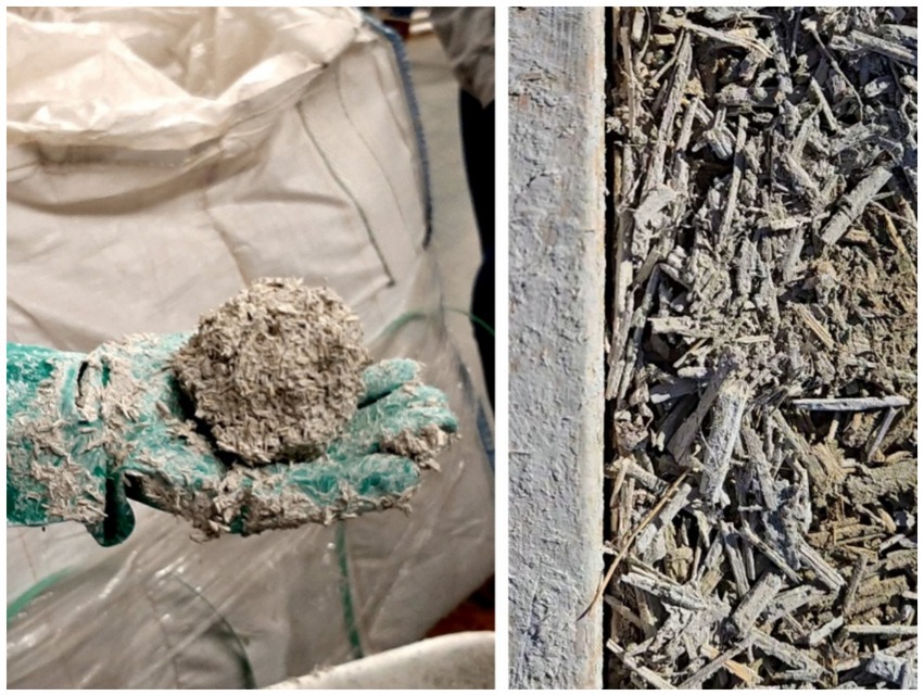
Figure 16. Left, the snowball test evaluates the hempcrete mixture’s ability to consolidate. Right, the dried hempcrete adjacent to wood structure; the shrinkage gap visible between the wood structure and the hempcrete is discussed later.
Durability and moisture resistance of the ZCMH’s assemblies is another topic for further observation and longer-term research. Like many “new” materials, the integration of hemp fiber and hempcrete in the ZCMH’s assemblies was informed by building science research and provisional experimentation. Tracking how these assemblies perform and hold up over time is an important commitment for the author, and further publication of these results is planned (Figure 17).
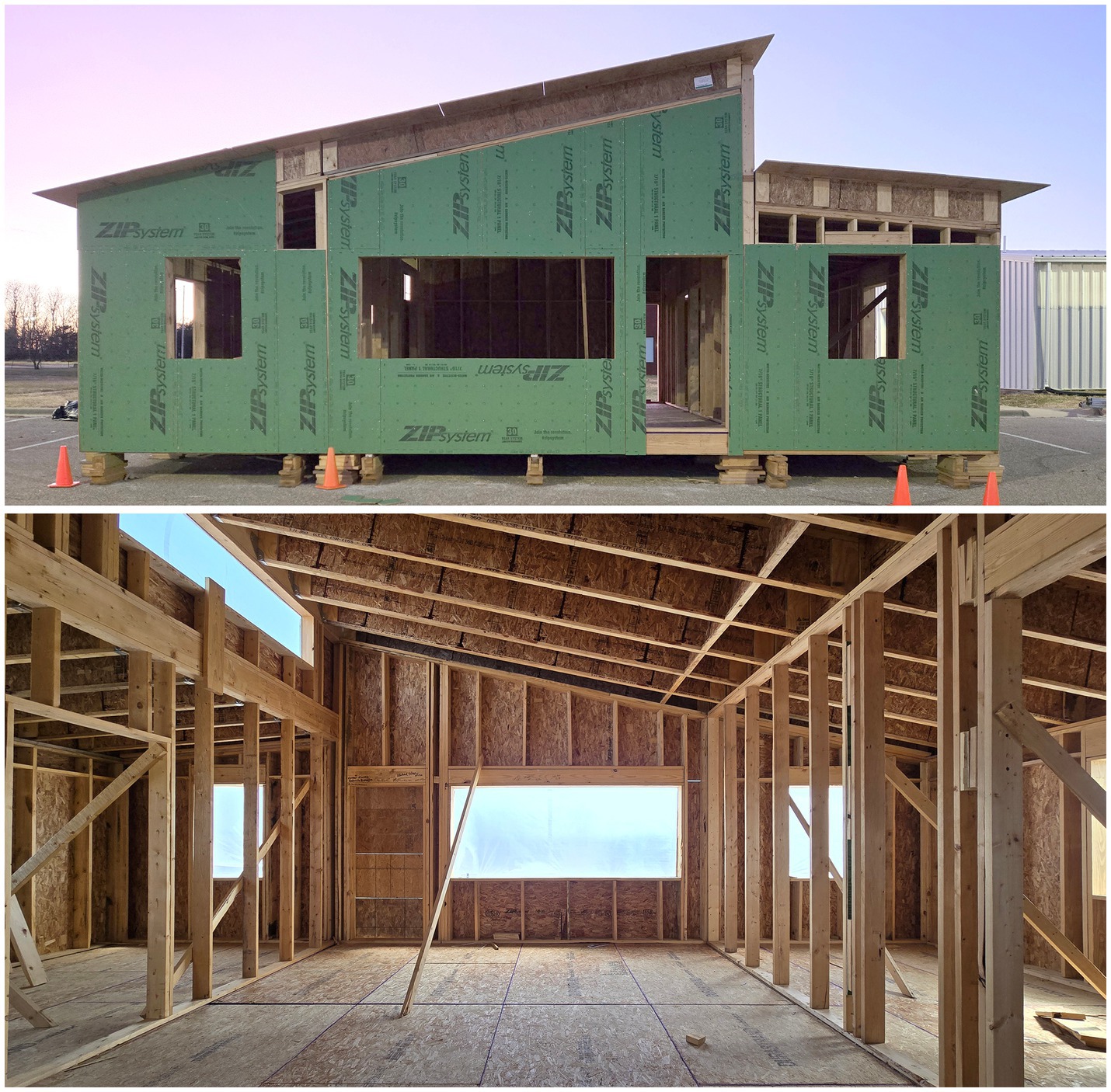
Figure 17. The assembled prefab components of the ZCMH awaiting transport to the site in February 2025, while preparation of the site and foundations in nearby Ogden, Kansas is completed (Source: Author).
Lastly, the ZCMH also promised to be affordable and replicable, in addition to net zero carbon. In terms of affordability, construction costs (labor and material) continued to climb throughout the project, on items that were unrelated to hemp materials and other zero-carbon strategies. Using the most recent actual and projected costs from HHNFH (with applied values for volunteering, trades-based education, donations, and subcontracted items) the ZCMH is tracking to be completed for $255,000, or $295/ft2. Using the same accounting framework, a larger 3-bed, 2-bath net zero home built by the same HHNFH partnership and designed by the studio in 2023 was completed for $221,000 ($168/sq. ft). Supplemented by volunteers, trades-based education, grants, and other tools, the ZCMH is still expected to be sold close to its affordability target of $150,000. In order to achieve zero carbon, the ZCMH increased labor time (for the hempcrete) and increased some specific material costs (hemp fiber insulation, 2×8 wall construction, engineered lumber in the roof) which naturally increased the per-square-foot cost of construction; making the home as compact as possible allowed the total construction cost of the house to increase less dramatically, a 15% increase, versus the 2023 build. Moreover, both builds are still well below the average listed existing and new home price in the surrounding market. Combining small-footprint design with improvements in labor efficiency and future cost moderation of hemp materials will further close the gap between conventional and zero carbon construction.
The ZCMH used progressive technology for design, analysis, and information management, but in terms of replicability, the ZCMH demonstrated that low and zero carbon construction techniques could leverage the methods and skill sets associated with conventional construction in the U.S. This allowed the ZCMH to serve as an educational experience for participating partners, including professional college students, technical college students, and workforce trainees who took part in construction. While the hempcrete aspect of the project required some specific knowledge and expertise, it was a process that students and trainees could confidently master among other construction skills.
5 Conclusion
While net zero carbon buildings are becoming more common today, the Zero Carbon Microhome puts forward a model of integrating hempcrete and hemp building materials in a replicable model that promises affordability and performance. Net zero energy homes achieve affordability by setting realistic goals, tracking project performance with analysis tools, and incorporating a robust design process that integrates materials, assemblies, details, and systems. A net zero carbon home, like the ZCMH, can use the same approach to balance sustainability, performance, and affordability. While some aspects of the ZCMH are innovative, the means and methods to build a net zero carbon, net zero energy home like the ZCMH are available and ready for willing owners, designers, and builders to deploy.
Data availability statement
The raw data supporting the conclusions of this article will be made available by the authors, without undue reservation.
Author contributions
MG: Supervision, Project administration, Validation, Writing – review & editing, Methodology, Data curation, Conceptualization, Writing – original draft, Investigation, Software, Formal analysis, Resources, Funding acquisition, Visualization.
Funding
The author(s) declare that financial support was received for the research and/or publication of this article. The project received a $50,000 K-State 105 Engagement Incentive Grant from Kansas State University.
Acknowledgments
The author would like to thank the following graduate architecture students in the Fall 2024 Net Positive Studio for their work designing, developing, and helping to build the project: Kaden Beck, Natalie Bell, Rylee Boyd, Mario Castro-Cortes, Delaney Ferguson, Gabriela Hernandez Morales, Seongyun (Jason) Jeong, Rebecca Kwasnica, Seth Larson, Connor Martin, Seth McQuery, Naia Tunks, and Joseph Winter. The author also thanks students Mahlee Wohlford and Carter Wiens for developing the original concept for the microhome. Lastly, the author recognizes the collaborative effort and support of the project’s sponsor, Habitat for Humanity of the Northern Flint Hills, and the partners of the Workforce Solar Housing Partnership that made this project possible: Manhattan Area Technical College, Ft. Riley Homebuilders Institute, Flint Hills Job Corp, Manhattan Housing Association, and Flint Hills Renewable Energy and Efficiency Cooperative.
Conflict of interest
The author declares that the research was conducted in the absence of any commercial or financial relationships that could be construed as a potential conflict of interest.
Generative AI statement
The author(s) declare that no Gen AI was used in the creation of this manuscript.
Any alternative text (alt text) provided alongside figures in this article has been generated by Frontiers with the support of artificial intelligence and reasonable efforts have been made to ensure accuracy, including review by the authors wherever possible. If you identify any issues, please contact us.
Publisher’s note
All claims expressed in this article are solely those of the authors and do not necessarily represent those of their affiliated organizations, or those of the publisher, the editors and the reviewers. Any product that may be evaluated in this article, or claim that may be made by its manufacturer, is not guaranteed or endorsed by the publisher.
References
American Society for Testing and Materials (2013). “ASTM C1155-95: standard practice for determining thermal resistance of building envelope components from the in-situ data” in West Conshohocken (PA: ASTM International).
Arehart, J., Nelson, W., and Srubar, W. (2020). On the theoretical carbon storage and carbon sequestration potential of hempcrete. J. Clean. Prod. 266:121846. doi: 10.1016/j.jclepro.2020.121846
Arnaud, L., and Gourlay, E. (2012). ‘Experimental study of parameters influencing mechanical properties of hemp concretes,’ Construction and Building Materials, 28:50–56.
Builders for Climate Action. (2025) BEAM–Building Emissions Accounting for Materials v1.1. Available online at: https://www.buildersforclimateaction.org/beam-estimator.html (accessed March 27, 2025).
Chuosavasdi, T., Stitmannaithum, B., Sumranwanich, T., Saengsoy, W., and Tangtermsirikul, S. (2016). Degree of hydration and mass balance equations for determination of mix proportion of hardened OPC concrete. Eng. J. 20, 211–219. doi: 10.4186/ej.2016.20.2.211
Florentin, Y., Pearlmutter, D., Givoni, B., and Gal, E. (2017). A life-cycle energy and carbon analysis of hemp-lime bio-composite building materials. Energ. Build. 156, 293–305. doi: 10.1016/j.enbuild.2017.09.097
Gibson, M. (2024a). “Getting real with hemp in residential construction.” in Residential Building Design and Construction Conference, Pennsylvania State University, March 27-28, 2024.
Gibson, M. (2024b). “Lean tech, high performance: balancing affordability and Technology in net Zero Housing” in Transforming issued in housing design. ed. K. Gular (Hoboken, New Jersey: Wiley), 43–57.
Gill, Z. (2025). “Cultivation methods of prairie band ag LLC grown and processed hemp Hurd.” in Interview by Michael Gibson, March 26, 2025.
Hempitecture. (2025a) HempWool Life Cycle Assessment. Available online at: https://www.hempitecture.com/post/hempwool-life-cycle-assessment/?srsltid=AfmBOorG6NCRKIyD5aL2aC3OIjv3YaDmgLTRx66U70SsUAN-8dM7jiPL (accessed March 31, 2025).
Hempitecture. (2025b) HempWool Technical Data Sheet. Available online at: https://www.hempitecture.com/wp-content/uploads/2024/11/HempWool_Technical-Data-Sheet.pdf (accessed April 1, 2025).
International Code Council. (2024). International Residential Code. International Code Council. Falls Church, Va.: International Code Council, 2024.
Jami, T., Karade, S., and Singh, L. (2018). “Hemp concrete – a traditional and novel green building material.” International Conference on Advances in Construction Materials and Structures (ACMS-2018), IIT Roorkee, Roorkee, Uttarakhand, India.
Kansas Housing Resources Corporation (KHRC). (2021) Kansas Statewide Housing Needs Assessment. Available online at: https://kshousingcorp.org/wp-content/uploads/2022/02/2021_01-14-Kansas-Housing-Assessment-Section-1-Low-Res.pdf (accessed June 22, 2022).
Nováková, Petra. (2018). “Use of technical hemp in the construction industry.” in MATEC Web Conf. Volume 146. 9th International Scientific Conference on Building Defects (Building Defects 2017).
Pretot, S., Collet, F., and Garnier, C. (2014). Life cycle assessment of a hemp concrete wall: impact of thickness and coating. Build. Environ. 72, 223–231. doi: 10.1016/j.buildenv.2013.11.010
Realtor.com (2025) Available online at: https://www.realtor.com/realestateandhomes-search/Manhattan_KS/shw-nc (Accessed August 16, 2025).
Sáez-Pérez, M., Brümmer, M., and Durán-Suárez, J. (2020). A review of the factors affecting the properties and performance of hemp aggregate concretes. J. Build. Eng. 31:101323. doi: 10.1016/j.jobe.2020.101323
Stanwix, W., and Sparrow, A. (2014). The Hempcrete book: Designing and building with hemp-lime. Cambridge UK: Green Books.
U.S. Census. (2023a). American Community Survey. Available online at: https://www.census.gov/programs-surveys/acs/data.html (accessed Aug 20, 2024).
U.S. Census. (2023b). Characteristics of New Housing Reports. Available online at: https://www.census.gov/construction/chars/index.html (accessed Aug 20, 2024).
U.S. Department of Energy, Energy Information Administration. (2022). 2020 Residential Energy Consumption Survey. Available online at: https://www.eia.gov/consumption/residential/data/2020/ (accessed May 13, 2024).
U.S. Department of Energy, Energy Information Administration. (2024a) U.S. energy consumption by source and sector, 2023 [graphic]. Available online at: https://www.eia.gov/energyexplained/us-energy-facts/images/consumption-by-source-and-sector.pdf (accessed March 25, 2025).
U.S. Department of Energy, Energy Information Administration. (2024b) State Electricity Profiles. Available online at: https://www.eia.gov/electricity/state/kansas/ (accessed March 25, 2025).
United States Green Building Council (USGBC). (2025) LEED v5 BD+C Carbon Assessment. Available online at: https://www.usgbc.org/credits/new-construction/v5-public-comment-1-1?return=/credits/New%20Construction/v5%20-%20Public%20Comment%201 (accessed April 1, 2025).
Wilson, N., Aloumon, C., Tauheed, L., and Kennedy, K. (2023) The Impact of a Weatherization Program on the Health Outcomes for Children with Asthma. Available online at: https://metroenergy.org/wp-content/uploads/2023/07/Health-Impacts-of-EWKC-Program-Activities.pdf (accessed March 27, 2025).
Keywords: hempcrete, hemp, net zero carbon, net zero energy, affordable housing
Citation: Gibson MD (2025) Integrating hemp in a replicable model for affordable, low carbon housing: a zero carbon microhome prototype for the Kansas Flint Hills. Front. Sustain. 6:1606205. doi: 10.3389/frsus.2025.1606205
Edited by:
Ali M. Memari, The Pennsylvania State University (PSU), United StatesReviewed by:
Jose De Jesus Perez Bueno, Center of Research and Technologic Development in Electrochemistry, MexicoWei Tong, The Pennsylvania State University (PSU), United States
Copyright © 2025 Gibson. This is an open-access article distributed under the terms of the Creative Commons Attribution License (CC BY). The use, distribution or reproduction in other forums is permitted, provided the original author(s) and the copyright owner(s) are credited and that the original publication in this journal is cited, in accordance with accepted academic practice. No use, distribution or reproduction is permitted which does not comply with these terms.
*Correspondence: Michael D. Gibson, bWRnaWJzb25Aa3N1LmVkdQ==