 Jiseon You
 Gimi A. Rimbu
 Lauren Wallis1
 John Greenman
 Ioannis Ieropoulos
- 1Bristol BioEnergy Centre, University of the West of England, Bristol, United Kingdom
- 2National Institute for R&D in Electrical Engineering ICPE-CA, Bucharest, Romania
In this study, possibilities of integrating microbial fuel cell (MFC) technology and buildings were investigated. Three kinds of conventional house bricks from two different locations were tested as MFC reactors and their electrochemical characteristics were analysed. European standard off-the-shelf house bricks generated a maximum power of 1.2 mW (13.5 mW m−2) when fed with human urine. Ugandan house air bricks produced a maximum power of 2.7 mW (32.8 mW m−2), again with human urine. Different cathode types made by surface modifications using two kinds of carbon compounds and two PTFE based binders were tested in both wet and dry cathode conditions. The effects of both anode and cathode sizes, electrode connection, electrode configuration, and feedstock on brick MFC power generation were also studied. Water absorption test results showed higher porosity for the Ugandan air bricks than European engineering bricks, which contributed to its higher performance. This study suggests that the idea of converting existing and future buildings to micro-power stations and micro-treatment plants with the help of integrated MFCs and other renewable technologies is achievable, which will be a step closer to a truly sustainable life.
Introduction
Increasing global greenhouse gas emission through burning fossil fuels causes climate change. In spite of rapidly growing global energy demands, on the other hand, nearly 1.1 billion people still have no access to electricity (WEO-2017 Special Report: Energy Access Outlook, 2017). Therefore, there is no doubt that implementing a shift in where we obtain our energy from must be made in order to face global energy challenges (World Energy Scenarios 2016 - the Grand Transition, 2016). Sustainable energy portfolios with reliable energy supplies should consist of various renewable energy sources, since there is no clear winner among the renewable energy technologies in terms of power density and geological availability.
Although global urbanisation is a major trend, there is an increasing interest in distributed generation also known as on-site generation. Unlike conventional power stations which are usually large-scale and centralised, and are often required to cover large supply areas, resulting in long distance of energy transmission, distributed, or decentralised generation systems are more flexible in terms of available energy generating/storage technologies and locations. A shift to microgrid systems accompanying distributed energy resources (DERs) has already begun and is reaching commercial markets. This is driven by technological developments and growing recognition of their benefits such as energy security improvement, economic benefits, and lowering environmental impact (Hirsch et al., 2018).
In DER systems, various technologies can be used and should preferably be used to generate energy. In this context, existing and future buildings are expected to play a crucial role. According to the recast of the Energy Performance of Buildings Directive (Directive 2010/31/EU), all new buildings in the EU should consume nearly zero-energy by the end of 2020. Not only are buildings the largest energy end-use sector (about 40% of total final energy use in the EU-28 and USA) (Bosseboeuf et al., 2015; EIA, 2019), buildings can also be sources of energy generation with the help of renewable energy technologies.
Microbial fuel cells (MFCs) are one of the emerging renewable energy technologies, producing electricity from organic matter including waste, using microorganisms. The dual-utility aspect of the technology, i.e., energy recovery from waste whilst cleaning the waste, makes it stand out among other renewable energy technologies. Energy density of an individual MFC unit is relatively low however, thus it is necessary to scale-up to gain a meaningful power output for practical applications. To scale-up, physical stacking and electrical connections of multiple MFC units have been suggested (Ieropoulos et al., 2008; Asensio et al., 2017). Recent studies have proven that various porous materials can be used as an MFC separator with comparable performance at a much lower cost compared to ion selective membranes (Zhang et al., 2010; Moon et al., 2015; Kim et al., 2016; Winfield et al., 2016). In this way, a building brick might be able to serve as an MFC separator as well as a chassis.
The idea of integrating MFC technology and buildings is very fascinating as buildings will be able to generate the power they need on site. This integrated approach can be widely implemented in both developing countries as well as developed countries, since bricks are ubiquitous. This is a paradigm shift for conventional building concepts, from energy consumer to energy provider. Moreover, this on-site energy generation can lessen the load of central waste treatment systems.
However, as recently shown, achieving a decent level of power output as well as waste treatment efficiency from an individual module can be challenging, as this requires rigorous design and optimisation (Walter et al., 2016). Therefore, this study is focused on how the integration of various MFC elements can be achieved in the context of a “living wall” and optimised based on the understanding of processes and current available materials. For this work, three types of conventional house bricks from two different locations were tested as MFC reactors and their electrochemical characteristics analysed. More specifically, different cathode types, the size of both anode and cathode, electrode connection, electrode configuration, and potential feedstock were tested. A material characteristic analysis of a test brick was also performed and the prospects of the integration have been presented.
Materials and Methods
Test Bricks
Three types of real building bricks from two locations were obtained for this study. The first two bricks (Type 1) are essentially standard off-the-shelf house bricks purchased from the same manufacturer (Wienerberger, Cheshire, UK). These are commonly used house bricks in the UK. Both have the same dimension of 215 × 102 × 65 mm (W × D × H). Brick B (product name: Avenue smooth black), has six holes, each being 28.6 mL (10 × 44 × 65 mm), whereas brick R (product name: Staffordshire smooth crimson) has five holes which are bigger than brick B's (66.3 mL each, 17 × 60 × 65 mm). The distance between each compartment is 21 and 18.5 mm for brick B and brick R, respectively. Technical specification of brick B and brick R is presented in the Supplementary Material.
As an additional test with real house bricks, air bricks handmade by a local potter in Uganda was selected as the final test brick (named as brick O, Type 2). It was sourced during one of the Bristol Bioenergy Center field trials of the Pee Power® urinal (funded by the Bill & Melinda Gates Foundation grant no. OPP1149065), as an example of a local airbrick. The original size of the brick was 220 × 35 × 80 mm (W × D × H) with grooves of 2–3 mm depth on each side. Two different electrode configurations were tested with this brick, and for one configuration (external cathodes and internal anodes) these grooves were removed by cutting the sides off by 3 mm. It has six holes, with a volume of about 13 ml (13 × 13 × 80 mm) each.
Brick MFC Assembly and Operation
Type 1 Brick MFCs
Without any structural modifications to the brick, brick “B” and brick “R” were used to build a Type 1 MFC. These type of brick MFCs used perforations as anode or cathode chambers, which were arranged alternately. Since the two bricks had a different number of holes (six for brick B and five for brick R) each with a different volume, brick B MFCs had three anodes and three cathodes (Figure 1A), whereas brick R MFCs had three anodes and two cathodes (Figure 1B). For the anode, plain carbon fibre veil (20 g m−2 carbon loading; PRF Composite Materials Poole, Dorset, UK) was cut into different sizes and then folded in order to fit into the chambers. Using these type of brick MFCs, several tests were carried out, to investigate the effect of cathode type, electrode size, feedstock, and cathode surface modification on the MFC power performance. For cathode tests, cathodes were operated in two conditions; either dry or wet. Air was circulated at 189 ml hr−1 using a peristaltic pump (205U, Watson Marlow, Falmouth, UK) for dry cathodes, whereas wet cathodes were flooded with recirculated synthetic saline water (3.5% NaCl in deionized water) at a flow rate of 189 ml hr−1. Two types of feedstock were tested; municipal wastewater collected from a local wastewater treatment plant (Wessex Water, Saltford, UK) and human urine donated from consenting adults. Feedstock was supplied continuously at a flow rate of 95 ml hr−1 for both brick B and brick R. The tested cathode surface modification is described in the section below.
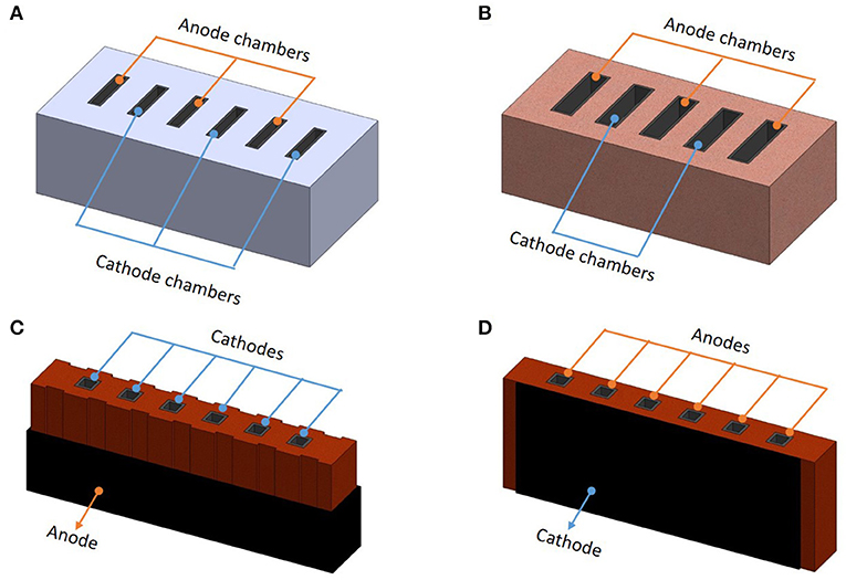
Figure 1. Schematic diagrams of the tested brick MFCs: (A) Type 1 brick B MFC with three anode chambers and three cathode chambers. (B) Type 1 brick R MFC with three anode chambers and two cathode chambers. (C) Type 2 brick O MFC with one external anode and six internal cathodes. (D) Type 2 brick O MFC with two external cathodes and six internal anodes.
Type 2 Brick MFCs
For the anode/cathode configuration test, brick “O” was used to build the Type 2 brick MFCs. All six perforations of brick O, each with a volume of about 13 ml, were used as either anode or cathode chambers. For the original shaped brick O (internal cathode and external anode version), six 21 cm2 (3 ×7 cm) size cathodes were placed inside the perforations. The bottom of the cathode chambers were sealed with an acrylic sheet and the top was left open to air. Cathodes were hot-pressed with activated carbon onto stainless steel mesh (Walter et al., 2018) and all six cathodes were electrically connected through a 0.3 mm Ni-Cr wire. A plain carbon veil anode of 810 cm2 was wrapped outside of the brick (Figure 1C). This MFC was then placed in a plastic container containing 2.4 L human urine as the anode feedstock. MFCs were fed in batches; 500 ml of feedstock was replaced twice a week. For the other electrode configuration, structural modification was done to smoothen both sides of brick O (internal anode and external cathode version) in order to improve the physical contact between the cathodes and the body of the brick. Six internal anodes made of plain carbon veils with a total surface area of 810 cm2 (135 cm2 each), were put inside perforations and electrically connected. The internal anode brick MFC holds a 78 ml anolyte volume in total. Two cathodes (total surface area of 160 cm2 each), made of the same hot-pressed activated carbon, were placed outside of the brick (Figure 1D) and also electrically connected. These internal anode-version brick MFCs were fed human urine continuously at a flow rate of 15 ml hr−1.
Both Type 1 and 2 MFCs were inoculated with activated sludge (pH 7.8) (Wessex Water Scientific Laboratory, Saltford, UK) enriched with 1% tryptone and 0.5% yeast extract. Various external loads were used throughout the work, based on polarisation runs.
Figure 1 shows a schematic diagrams of the tested brick MFCs. Photos of experimental set-up for each brick MFC are presented in the Supplementary Material.
Cathode Surface Modification of Type 1 MFCs
A total of four types of cathodes were tested in Type 1 MFCs, three of which were modified. As a control, a plain carbon veil sheet (same as the anode material) without any modification was used only on brick R MFCs (named as R_plain). Another control was prepared as previously described (You et al., 2015); hot pressing activated carbon onto the plain carbon veil sheet using 20% PTFE (polytetrafluoroethylene) as a binder (carbon loading: 60 mg cm−2). This PTFE also provides hydrophobicity to the cathode. The other two types of cathode modifications were made by mixing activated carbon (G. Baldwin & Co., London, UK) or carbon black (Vulcan XC 72R, Cabot Corporation, Georgia, USA) with 5% Nafion (Nafion 117, Sigma-Aldrich, Dorset, UK), then painting this mixture onto the plain carbon veil sheet. Both modifications resulted in additional carbon loading of 2 mg cm−2. All these modifications were prepared in ambient conditions without a heating process.
Details of each test MFC are presented in Table 1.
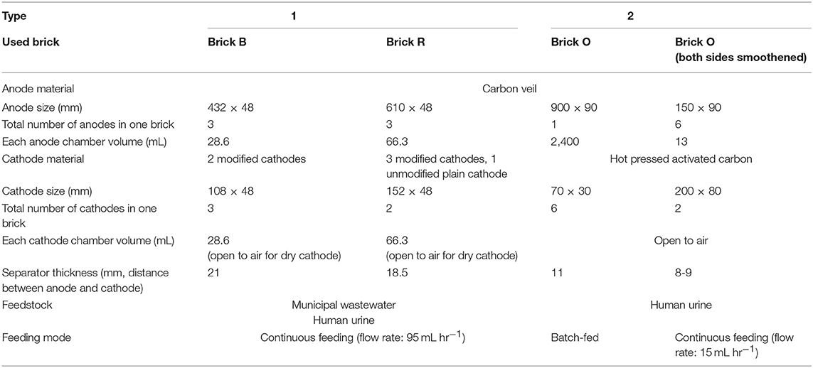
Table 1. Details of test brick MFCs.
Data Logging and Performance Analysis
Power output of the MFCs was monitored in real time in volts (V) against time using a multi-channel Agilent 34972A DAQ unit (Agilent Technologies, California, USA) every 5 min. For polarisation sweeps, various external resistances ranging from 38 kΩ to 1 Ω were loaded every 5 min and the potential between the anode and cathode was recorded every 30 s. All experiments were carried out in a temperature-controlled environment, at 22 ± 2°C.
Water Absorption Measurement
To measure the water absorption of test bricks, brick samples were dried in a ventilated oven at a temperature of 110°C until they attained a substantially constant mass. Samples were then cooled to room temperature to be weighed (M1). Dry samples were immersed completely in deionized water at room temperature for 24 h. After taking out the samples, any trace of water was wiped out with damp cloth and samples were weighed within 3 min after they had been removed from water (M2). Water absorption is calculated as follows;
Results and Discussion
Cathode Comparison
Two types of carbon (activated carbon and carbon black) and binder (Nafion and PTFE) were used to modify the plain carbon veil cathode surface. The additional carbon increased the electrode surface area and both Nafion and PTFE served as a binder, as well as rendering the carbon veil based cathode more hydrophobic, which can be more suitable for an efficient cathode reaction (Li et al., 2010; Chi et al., 2018). A total of four types of cathodes including one control (unmodified plain carbon veil cathode) were tested in two running conditions, dry and wet. Figure 2 shows the maximum power outputs from polarisation sweeps running on brick MFCs with these cathodes.
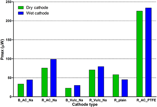
Figure 2. Maximum power output from polarisation measurements of the test cathode types of Type 1 test bricks. Polarisation was performed between single anode and cathode of each brick.
When electrons, protons and oxygen from free air react in the cathode to ‘close the circuit' (when electricity is generated), water is formed on the cathode (Equation 2). Unlike some very conductive metals, such as silver, gold, and copper, conductivity of carbon-based electrode materials are comparatively low. For example, measured resistivity of plain carbon veil used in this study was 4.6 ×10⁻⁴ Ω · m (at 20°C) (You et al., 2014). For this kind of air breathing cathodes (dry cathodes), water formation on the cathode is beneficial as it maintains the electrode wet thereby facilitating the continuous flow of cations from the anode. However, too much water formation hinders the electricity generation by covering reactive sites and lowering conductivity. This is known as “cathode flooding” (Yu et al., 2009; You et al., 2015). Therefore, it was thought that maintaining a dry condition and subsequently preventing cathode flooding by the constant supply of air could enhance the cathode performance.
In general, dry cathodes produced 4–25% less power outputs than wet cathodes of the same kind, except for the plain cathode used in brick R (R_plain). This is thought to be due to excessive amounts of air blown into the cathodes, which evaporated moisture from the cathodes, thus lowering their conductivity. Whereas, for plain carbon veil material, supplying air to keep it less “wet” helped its current generation. Unlike modified cathodes which are more hydrophobic, once plain carbon veil becomes wet, it holds water well. Thus, cathode running in a dry condition by a continuous supply of air seems like a better option for this material. On the other hand, all of the modified cathodes, which are more hydrophobic, benefited from 3.5% saline water, since it provided sufficient moisture as well as higher conductivity.
In terms of modification components, a mixture of activated carbon and PTFE outperformed all other combinations. The best combination, activated carbon and PTFE modified cathode, produced 233.9 μW (wet R_AC_PTFE cathode), which is 2.4 times higher than the second-best cathode modified with activated carbon and Nafion (98.8 μW; wet R_AC_Na cathode). The lowest output was produced from a carbon black and Nafion combination (79.5 μW; wet R_Vulc_Na cathode) and the same order of cathode performance regarding the modification combination was also observed in brick B.
When comparing the two test bricks, brick R showed better performance than brick B. Although the total surface area of all cathodes placed in brick B was larger (155.5 cm2) than brick R (145.9 cm2), the distance between the anode and cathode chambers was longer for brick B (21.0 mm) than for brick R (18.5 mm). According to previous studies (Winfield et al., 2013; Pasternak et al., 2016), thickness of the ceramic separator plays a crucial role in the MFC power generation. In this case, brick R benefits from its thinner internal brick walls.
Electrode Configuration
Holes in bricks allow the bricks to dry faster, require less material to build, make them weigh less and provide space for mortar to lock the bricks together. In this study, these holes were used as either anode or cathode chambers without major alterations to the original brick structure. For Type 1 bricks, anodes and cathodes were placed in the holes alternately, resulting in brick MFCs with multiple electrodes. Since these electrodes were separate, different ways of connecting them electronically and corresponding power performance were investigated.
Figure 3 illustrates power curves of brick B and brick R with their best performing cathodes, AC_Na and AC_PTFE, respectively. For both brick MFCs, parallel connection of all available electrodes was the best option, in terms of power output. When connecting all three anodes and cathodes of brick B in parallel, the maximum power output (PMAX) was 143.8 μW which was 2.3 times higher than PMAX of the same electrodes connected in series (62.8 μW). This was possible due to fluid cross over between chambers, either because of material porosity or sealing between the perforations, which provided an alternative electron path that was opposing the electron flow through the connecting wires. For both parallel and series connections, maximum power output levels increased when additional electrodes were connected. This is easily predictable since a higher number of electrodes provide a more reactive surface, resulting in powers adding up. However, the degree of increment was more significant for parallel connection than serial connection (Figure 3C), perhaps for the same reasons mentioned above.
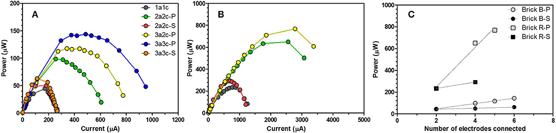
Figure 3. Power curves of the best cathode of each tested Type 1 brick and maximum power output of each polarisation sweep. (A) B_AC_Na wet cathode (B) R_AC_PTFE wet cathode (C) maximum power output of each configuration in relation to the total number of electrodes (both anode and cathode) connected. In the legend, figures indicate the number of anodes or cathodes connected, letters “a,” “c,” “P,” and “S” represent anode electrode, cathode electrode, parallel connection and serial connection, respectively.
Feedstock Comparison
Following the electrode connection investigation, two kinds of feedstock were tested in the brick MFCs with all anodes and cathodes connected in parallel. Neat human urine and municipal wastewater enriched with extra nutrients (1% tryptone, 0.5 % yeast extract and 5 mm sodium acetate) were chosen for this set of tests, since these can be easily supplied from residential building environments. Both types of feedstock were supplied continuously at a flow rate of 95 ml hr−1, which resulted in hydraulic retention time (HRT) of 0.3 and 0.7 h for brick B and brick R, respectively. Once power outputs from brick MFCs running on each feedstock stabilised, polarisation tests were performed. The PMAX of each test brick MFC is shown in Figure 4.
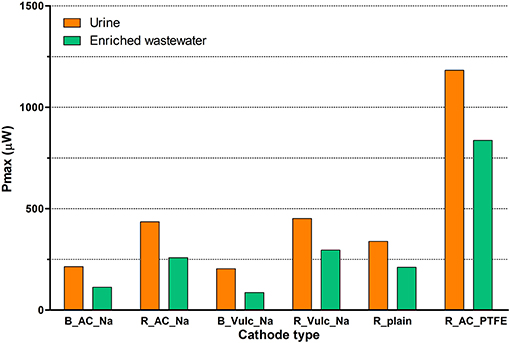
Figure 4. Maximum power outputs of different feedstock tested in Type 1 brick MFCs. PMAX was calculated from power curves. All anodes and cathodes in a single brick connected in parallel.
Despite varying degrees of difference (41–136%), urine outperformed wastewater, as a feedstock, in terms of power output in all cases. The best performing cathode type, R_AC_PTFE, generated 1182.4 μW when fed with urine. This was 41% higher than wastewater which produced 837.0 μW. Despite the relatively small portion of readily available carbon compounds presented in urine, it has proven to be a better fuel for MFC power generation (Ieropoulos et al., 2012, 2013). Its high conductivity, neutral-to-alkali pH, and a good combination of nitrogen, phosphorous, and potassium (all essential building blocks for new biomass, for which microbes have high affinity) are thought to contribute to its high conversion rate to electrical current output; more studies are required to further elucidate how urine works in MFCs.
In the scenario of integrating MFC technology into buildings, such as domestic dwellings or offices, wastewater produced onsite can be used as a feedstock for the MFCs. In a domestic setting, greywater include streams from different sources such as the bathroom, kitchen, dishwasher or laundry, in addition to blackwater. Given that urine is an excellent fuel for MFCs, such systems in buildings can be fed with urine only or toilet flush water from source separating toilets, resulting in diluted urine. Greywater can be used for flushing toilets to save water consumption in buildings and provide an extra carbon source to MFCs.
Electrode Position and Analysis of Brick Characteristics for Type 2 MFCs
Following the tests with European off-the-shelf bricks, as part of a wider campaign, bricks and brick materials from our trial site in Uganda were sourced and tested with the better performing urine feedstock. This section describes the test results and material characteristic analysis carried out with the additional test bricks (brick O-Type 2 bricks).
First, instead of using brick holes as cathode and anode chambers alternately, different electrode configurations were investigated by changing the position of electrodes either internally or externally (Figures 1C,D). This is another way of using the brick holes as chambers, and in this configuration, the wall between a hole and the outer brick acts as a separator between the anode and cathode. The thickness of this wall is 11–13 mm.
Figure 5 depicts polarisation and power curves of both internal cathode and internal anode version MFCs. Internal cathode version MFCs showed maximum power output of 2.7 ± 0.5 mW and maximum current over 20 mA. Open circuit voltage was 639.7 ± 33.0 mV. Internal anode version MFCs presented lower performance with a maximum power output of 1.5 ± 0.2 mW. It should be noted that since these two kinds of MFCs (internal cathode or internal anode version) had different sizes of both electrodes and volume of anolytes, direct comparison between the two kinds was not intended. These tests were performed to explore possibilities of using real house bricks as MFC reactors with minimum structural alterations.
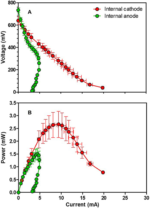
Figure 5. Polarisation (A) and power curves (B) of Type 2 brick MFCs. Data points are average values of triplicates.
Despite the relatively thick brick wall still acting as a separator, these levels of power outputs are quite encouraging, especially those from the internal cathode version MFCs, in comparison to Type 1 MFCs. This is thought to be mainly due to the thinner wall separator and higher specific porosity of the Type 2 bricks. Water absorption measurement results indicate that Type 2 bricks can absorb at least 2.7 and 1.6 times more water than brick B (<6%) and brick R (<10%) of Type 1 can, respectively, implying that Type 2 bricks are more porous compared to off-the-shelf standard European engineering bricks.
Power output levels of all test brick MFCs in their best conditions, based on absolute power, are presented in Table 2.
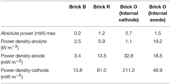
Table 2. Power outputs of test brick MFCs.
Conclusions
Commercially available standard house bricks demonstrated feasibility as MFC reactors without significant structural alterations, generating PMAX of 1.2 mW (13.5 mW m−2 normalised by total anode surface area, value from R_AC_PTFE). More porous air bricks (Type 2 brick MFCs) sourced from Uganda performed even better, with a PMAX of 2.7 mW (32.8 mW m−2). Although the power output levels produced from these brick MFCs were relatively low in comparison to recently reported work (Wang et al., 2017; Palanisamy et al., 2019), considering that no high-cost catalysts were used and that these bricks were not optimised as MFC systems, this work shows a high potential for self-sustainable systems. Type 2 brick MFC results are particularly encouraging, since they demonstrate the direct accessibility of MFC technology. It is possible to build MFC systems with locally available building materials, which could help the local economy of economically developing countries.
This study presents exemplar ways of utilising existing off-the-shelf bricks as MFCs. More bricks with different compositions, manufacturing processes, and designs can be further explored. Moreover, new designs and architectural concepts that can increase the functionality of bricks beyond simply load-bearing structures of buildings, and integrating MFC technology, should be investigated. The work presented herein is part of the Living Architecture project, which investigates the integration of MFCs, as well as other technologies in the “fabric” of buildings, to render these into self-sustainable habitats; further information can be found on the project website (https://livingarchitecture-h2020.eu).
The idea of converting existing and future buildings to micro-power stations as well as micro-treatment plants, with the help of MFCs and other potential renewable technologies, is definitely worth pursuing. In this way, zero-energy buildings are conceivable, which will be a step closer to a truly sustainable life.
Data Availability
The datasets generated for this study are available on request to the corresponding authors.
Author Contributions
II and JG conceived the original idea and along with JY, GR, and LW designed the experiments of this study. JY and GR carried out the laboratory work. JY and GR organised the database and performed the statistical analysis. JY wrote the first draft of the manuscript. All authors contributed to manuscript revision, read, and approved the submitted version.
Funding
The work has been supported by the European Commission Horizon 2020 FET-OPEN Living Architecture Project, grant number 686585 and the open access publication has been supported by the European Commission 2020 FET-OPEN “Active Living Infrastructure: Controlled Environment” project, grant number 851246.
Conflict of Interest Statement
The authors declare that the research was conducted in the absence of any commercial or financial relationships that could be construed as a potential conflict of interest.
Supplementary Material
The Supplementary Material for this article can be found online at: https://www.frontiersin.org/articles/10.3389/fenrg.2019.00094/full#supplementary-material
References
Asensio, Y., Mansilla, E., Fernandez-Marchante, C. M., Lobato, J., Cañizares, P., and Rodrigo, M. A. (2017). Towards the scale-up of bioelectrogenic technology: stacking microbial fuel cells to produce larger amounts of electricity. J. Appl. Electrochem. 47, 1115–1125. doi: 10.1007/s10800-017-1101-2
Bosseboeuf, D., Gynther, L., Lapillonne, B., and Pollier, K. (2015). Energy Efficiency Trends and Policies in the Household and Tertiary Sectors. Available online at: http://www.odyssee-mure.eu/publications/br/energy-efficiency-trends-policies-buildings.pdf (accessed June 20, 2019).
Chi, B., Hou, S., Liu, G., Deng, Y., Zeng, J., Song, H., et al. (2018). Tuning hydrophobic-hydrophilic balance of cathode catalyst layer to improve cell performance of proton exchange membrane fuel cell (PEMFC) by mixing polytetrafluoroethylene (PTFE). Electrochim. Acta 277, 110–115. doi: 10.1016/j.electacta.2018.04.213
EIA (2019). How Much Energy Is Consumed in U.S. Residential and Commercial Buildings? US Energy Inf. Assoc. Available online at: https://www.eia.gov/tools/faqs/faq.php?id=86&t=1.
Hirsch, A., Parag, Y., and Guerrero, J. (2018). Microgrids: a review of technologies, key drivers, and outstanding issues. Renew. Sustain. Energy Rev. 90, 402–411. doi: 10.1016/j.rser.2018.03.040
Ieropoulos, I., Gajda, I., You, J., and Greenman, J. (2013). Urine—waste or resource? The economic and social aspects. Rev. Adv. Sci. Eng. 2, 192–199. doi: 10.1166/rase.2013.1033
Ieropoulos, I., Greenman, J., and Melhuish, C. (2008). Microbial fuel cells based on carbon veil electrodes: stack configuration and scalability. Int. J. Energy Res. 32, 1228–1240. doi: 10.1002/er.1419
Ieropoulos, I., Greenman, J., and Melhuish, C. (2012). Urine utilization by microbial fuel cells; energy fuel for the future. Phys. Chem. Chem. Phys. 14, 94–8. doi: 10.1039/C1CP23213D
Kim, T., Kang, S., Sung, H., Kang, K., Kim, Y. H., and Jang, J. K. (2016). Characterization of polyester cloth as an alternative separator to Nafion membrane in microbial fuel cells for bioelectricity generation using swine wastewater. J. Microbiol. Biotechnol. 26, 2171–2178. doi: 10.4014/jmb.1608.08040
Li, A., Han, M., Chan, S. H., and Nguyen, N. (2010). Effects of hydrophobicity of the cathode catalyst layer on the performance of a PEM fuel cell. Electrochim. Acta 55, 2706–2711. doi: 10.1016/j.electacta.2009.12.048
Moon, J. M., Kondaveeti, S., and Min, B. (2015). Evaluation of low-cost separators for increased power generation in single chamber microbial fuel cells with membrane electrode assembly. Fuel Cells 15, 230–238. doi: 10.1002/fuce.201400036
Palanisamy, G., Jung, H.-Y., Sadhasivam, T., Kurkuri, M. D., Kim, S. C., and Roh, S.-H. (2019). A comprehensive review on microbial fuel cell technologies: Processes, utilization, and advanced developments in electrodes and membranes. J. Clean. Prod. 221, 598–621. doi: 10.1016/j.jclepro.2019.02.172
Pasternak, G., Greenman, J., and Ieropoulos, I. (2016). Comprehensive study on ceramic membranes for low-cost microbial fuel cells. ChemSusChem 9, 88–96. doi: 10.1002/cssc.201501320
Walter, X. A., Greenman, J., and Ieropoulos, I. (2018). Binder materials for the cathodes applied to self-stratifying membraneless microbial fuel cell. Bioelectrochemistry 123, 119–124. doi: 10.1016/j.bioelechem.2018.04.011
Walter, X. A., Stinchcombe, A., Greenman, J., and Ieropoulos, I. (2016). Urine transduction to usable energy: a modular MFC approach for smartphone and remote system charging. Appl. Energy 192, 575–581. doi: 10.1016/j.apenergy.2016.06.006
Wang, Z., Mahadevan, G. D., Wu, Y., and Zhao, F. (2017). Progress of air-breathing cathode in microbial fuel cells. J. Power Sources 356, 245–255. doi: 10.1016/j.jpowsour.2017.02.004
Winfield, J., Gajda, I., Greenman, J., and Ieropoulos, I. (2016). A review into the use of ceramics in microbial fuel cells. Bioresour. Technol. 215, 296–303. doi: 10.1016/j.biortech.2016.03.135
Winfield, J., Greenman, J., Huson, D., and Ieropoulos, I. (2013). Comparing terracotta and earthenware for multiple functionalities in microbial fuel cells. Bioprocess Biosyst. Eng. 36, 1913–1921. doi: 10.1007/s00449-013-0967-6
You, J., Santoro, C., Greenman, J., Melhuish, C., Cristiani, P., Li, B., et al. (2014). Micro-porous layer (MPL)-based anode for microbial fuel cells. Int. J. Hydrogen Energy 39, 21811–21818. doi: 10.1016/j.ijhydene.2014.07.136
You, J., Walter, X. A., Greenman, J., Melhuish, C., and Ieropoulos, I. (2015). Stability and reliability of anodic biofilms under different feedstock conditions: towards microbial fuel cell sensors. Sens. Bio-Sens. Res. 6, 43–50. doi: 10.1016/j.sbsr.2015.11.007
Yu, L., Chen, W., Qin, M., and Ren, G. (2009). Experimental research on water management in proton exchange membrane fuel cells. J. Power Sources 189, 882–887. doi: 10.1016/j.jpowsour.2009.01.037
Keywords: microbial fuel cell (MFC), living architecture, building brick, nearly zero-energy building, self-sustainable system
Citation: You J, Rimbu GA, Wallis L, Greenman J and Ieropoulos I (2019) Living Architecture: Toward Energy Generating Buildings Powered by Microbial Fuel Cells. Front. Energy Res. 7:94. doi: 10.3389/fenrg.2019.00094
Received: 25 June 2019; Accepted: 22 August 2019;
Published: 12 September 2019.
Edited by:
Uwe Schröder, Technische Universitat Braunschweig, GermanyCopyright © 2019 You, Rimbu, Wallis, Greenman and Ieropoulos. This is an open-access article distributed under the terms of the Creative Commons Attribution License (CC BY). The use, distribution or reproduction in other forums is permitted, provided the original author(s) and the copyright owner(s) are credited and that the original publication in this journal is cited, in accordance with accepted academic practice. No use, distribution or reproduction is permitted which does not comply with these terms.
*Correspondence: Jiseon You, amlzZW9uLnlvdUB1d2UuYWMudWs=; Ioannis Ieropoulos, aW9hbm5pcy5pZXJvcG91bG9zQGJybC5hYy51aw==