 Chunfeng Zheng1*
 Gang Wang
 Guangming Fan
- 1CNOOC Ener Tech-Drilling and Production Company, Tianjin, China
- 2Fundamental Science on Nuclear Safety and Simulation Technology Laboratory, Harbin Engineering University, Harbin, China
Gas-liquid separation technology is widely used in various fields of industrial production. In this research, a new kind of gas-liquid separator was proposed for the separation of gas-liquid mixture under different flow patterns. An inclined experimental system with an angle of 60 degrees from the vertical was established to test the new designed gas-liquid separator using of water and air as the working fluid. The experiment was conducted with the water flow rates covering 2.85–4.17 m3/h and the gas volume fraction covering 5–90%. Experiment results show that the separator can enable high efficient separation of gas-liquid mixtures under different patterns, especially under unstable flow patterns. The liquid level inside the separator is an important factor affecting the performance of the separator. On the basis of this, the critical liquid level of the separator was proposed for the practical application of the separator. This study fills the gap in the field of gas-liquid separation and provides a method for the separation of gas-liquid mixtures under different flow patterns.
Introduction
During the development of nuclear energy, gas, and liquid separation is important to ensure the safety of nuclear power plants (Matsubayashi et al., 2012). The centrifugal gas-liquid separator, which is characterized by small size and high reliability has been widely used in nuclear energy plants (Kataoka et al., 2009; Mao et al., 2018). With the further development of nuclear energy, the existing two-phase separation methods have encountered new challenges.
At present, the centrifugal gas-liquid separators used in the nuclear power plant are mainly divided into two categories: single-stage swirl-vane separator and multi-stages swirl-vane separator. The former is mainly used for the initial separation of water in steam, and the flow pattern of gas-liquid mixture to be separated is mainly annular flow or mist flow (Xiong et al., 2013, 2014; Mao et al., 2018). The latter is mainly designed for the separation of fission gas in Molt Salt Reactor (MSR). The gas volume fraction in the gas-liquid mixture to be separated is <0.5%, and the flow pattern of which is dispersed bubble flow (Nana et al., 2013; Cai et al., 2014). Whether the flow pattern is annular flow or bubble flow, the flow of the gas-liquid two-phase fluid is stable relatively that is beneficial to the separation of gas-liquid mixture. However, when the gas-liquid mixture is in unstable flow pattern, such as churn flow, the two-phase flow is characterized by violent oscillation (Taitel et al., 1980), which brings new problems to the efficient separation of gas-liquid mixture.
According to the way that the fluid enters into the separator, the centrifugal gas-liquid separator currently used in the industrial field can be distinguished into two categories. The first is called tangential or reversed flow cyclone and the other is axial cyclone (Nieuwstadt and Dirkzwager, 1995). In tangential flow cyclones, the flow is put into to the separator tangentially, which was first proposed in 1891 for the gas-liquid separation (Bai et al., 2011). The hydrocyclone and gas-liquid cylindrical cyclone (GLCC) are common tangential flow cyclones. A significant advantage of the tangential injection separator is its high swirl intensity and stable separation performance. As a disadvantage of such separator, it should be noted that the flow inside this kind of separator is highly turbulent and nonstationary, which limits the further application in two-phase flow separation (Hreiz et al., 2014a,b). On the other hand, limited by the space, most of the hydrocyclones and gas-liquid cylindrical cyclones are asymmetrical “single-entry” structures in practical applications, which leads to the asymmetrical internal flow field, and then affects the separation efficiency of the separator (Shi et al., 2012). Compared with the tangential flow cyclone, the flow is put into swirl motion by swirl generators in most of axial cyclones, which results in a relatively low swirl intensity of the fluid (Nieuwstadt and Dirkzwager, 1995). The pressure drop across the axial cyclone is less than that in the tangential flow cyclone. Experimental results show that the axial cyclone can maintain high separation efficiency only in high gas volume fraction, in which the flow of the gas-liquid two-phase mixture is relatively stable (Matsubayashi et al., 2012; Dixit et al., 2015). However, when the gas-liquid mixture before entering the separator is in unstable flow pattern, the separation efficiency drops sharply (Xiong et al., 2013, 2014; Funahashi et al., 2016).
From the above description, it can be found that the current gas-liquid separators are mainly designed for the separation of gas-liquid mixtures under the single and stable flow pattern. As a result, it is meaningful to design the separator can enable high efficient separation of gas-liquid mixtures under different flow patterns, especially under unstable flow patterns. In this paper, a new kind of gas-liquid separator was proposed for the high efficient separation of gas-liquid mixtures under different flow patterns, which fills the gap in the field of gas-liquid separation.
The Configuration and Operating Principle of the Gas-Liquid Separator
The separator, shown in Figure 1, is mainly consist of inner cylinder and outer cylinder. A swirl element is placed on the top of the inner cylinder whose main function is to put the fluid from linear motion to swirl motion and then centrifugal force is generated. There is an opening section on the upper part of the swirl element for discharging a part of the liquid from the liquid film formed under the action of centrifugal force. The liquid outlet and the gas outlet are arranged at the top and bottom of the outer cylinder, respectively. A baffle plate is placed below the gas outlet of the separator. On the other hand, there support bars are placed between the inner cylinder and outer cylinder to prevent the damage to separator caused by oscillation of gas-liquid fluid under unstable flow patterns.
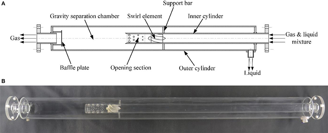
Figure 1. The configuration of the gas-liquid separator. (A) Section view of the separator. (B) Physical map of the separator.
The swirl element, displayed in Figure 2, is an important part of the separator. In order to ensure the accuracy of geometric parameters, the swirl element was processed by 3D printing. The function of swirl element is to form a swirling flow inside the inner cylinder and then the centrifugal force is generated. The swirl element has five identical vanes fixed to the hub, each of which is twisted and has a fixed inlet and outlet angle. α and β represent inlet angle and outlet angle of the swirl element, respectively, which are all angles to the central axis of the separator. Outlet angle (α) of the swirl elements is 55°, and inlet angle (β) is 0°. And the diameter of swirl element hub(Dh) is 18 mm.
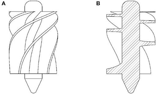
Figure 2. The swirl element used in the gas-liquid separator. (A) Main view. (B) Section view.
After the gas-liquid mixture enters the separator, the fluid is changed from the linear motion to the swirl motion and then the centrifugal force is generated with the guidance of vans in the swirl element. With the action of centrifugal force, the gas with a smaller density is concentrated in the center of inner cylinder and then an air core is formed. At the same time, the liquid with the larger density moves toward the inner wall of the inner cylinder and forms a liquid film around the air core. When the liquid film flows through the opening section, a part of the liquid in the liquid film is directly discharged into the annular chamber between the inner cylinder and the outer cylinder, and leaves the separator through the liquid outlet, thereby realizing the preliminary separation of the gas-liquid mixture. The design of opening section reduces the amount of liquid entering the gravity separation chamber by pre-separating a part of the liquid, which contributes to the improvement of separation efficiency, especially under unstable flow patterns. After leaving the inner cylinder, the gas-liquid mixture enters gravity separation chamber. With the action of gravity, the gas-liquid two-phase fluid is further separated in gravity separation chamber, which is the key to achieve efficient separation of gas-liquid mixture under unstable flow patterns. The baffle plate is used to prevent the liquid directly entering the gas outlet due to oscillation of gas-liquid two phase fluid under the unstable flow patterns. There is one detail needs to be mentioned is that the nozzle of the gas outlet extends a part to the inside of the outer cylinder. This design can effectively prevent some liquid droplets entering the gas outlet directly along the inner wall of the outer cylinder due to the entrainment of gas under the condition of high gas volume fraction.
Experimental System
An inclined experimental system with an angle of 60 degrees from the vertical was established, as shown in Figure 3, to test the performance of the separator. The experimental system is mainly composed of three parts: the water supply system, the air supply system, and the separator. In the air supply system, air was compressed by an air compressor and stored in a gas tank, which can maintain a stable air supply pressure. The air was supplied to the separator through the gas tank and air flow rate was varied by adjusting the control valve (V4). The water in the water tank enters the air-water mixer through a multi-stage centrifugal pump (Pump 2) and was mixed with air before entering the separator. During the operation of the separator, the separated water is discharged into the circulating water tank. With the action of a multi-stage centrifugal pump (Pump 1), the water in the circulating water tank is returned to the water storage tank. Water is recycled through two centrifugal pumps and two water tanks in the water supply system. The flow rates of gas and water into the separator can be measured by flow meters and denoted as Vg(m3/h) and Vl(m3/h), respectively. The experimental phenomenon inside the separator was recorded by a camera. The length of the straight pipe segment before gas-liquid two phase fluid entering the separator is 3.5 m and the inner diameter is 0.05 m (L/D >50), which could allow the flow pattern of gas-liquid mixture fully developed. A transparent organic glass tube with a length of 0.3 m is placed upstream of the separator, which is used to observe the flow pattern of gas-liquid mixture before entering the separator. The air and water at room temperature (18°C) were used for a series of experiments on the separator. All experiments were carried out under the atmospheric pressure.
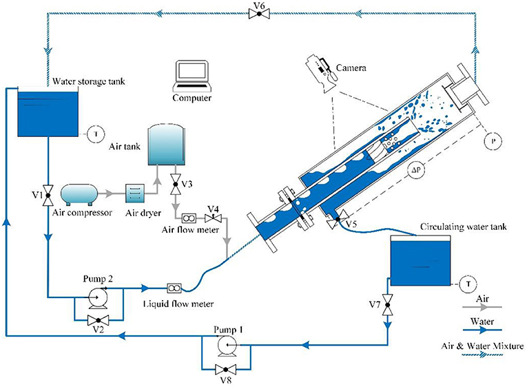
Figure 3. Experimental system.
According to the operation process of the separator, it can be known that the separator combines two separation principles: gravity separation and centrifugal separation. Considering the limitation of actual use environment, the separation performance of the separator was tested under the inclined condition.
The liquid level between the inner and outer cylinders of the separator can be adjusted by changing the opening of the valve (V5). In this experimental system, the liquid level was measured in two ways: a ruler attached to the surface of the separator and a differential pressure transmitter. In practice, the liquid level inside the separator is difficult to obtain directly. It is an ideal choice to measure liquid level by the differential pressure transmitter. At the same time, the accuracy of the liquid level measured by the differential pressure transmitter can be checked by comparing the liquid level measured by the ruler. The measurement principle of the differential pressure transmitter is as follows.
Ignoring the bubbles contained in the water inside the annular chamber between the inner and outer cylinders, the density of the fluid is considered to be the density of water. As shown in Figure 4, according to the Pascal principle, the following equation can be obtained.
In Equation (1), ρ is the water density and L denotes the liquid level between the inner and outer cylinders of the separator. And then the liquid level L can be expressed as:
The experimental data during the experiment were recorded using an NI (National Instruments) acquisition system. The relative deviation of instruments used in this experimental system are list in Table 1.
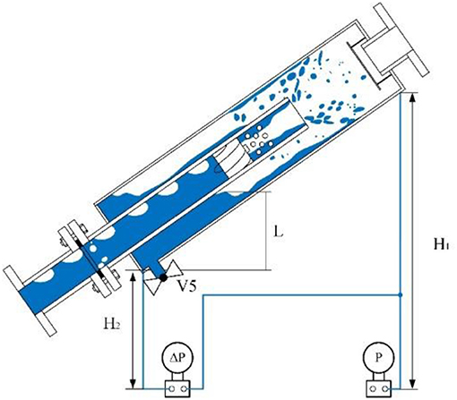
Figure 4. The liquid level measurement principle of the differential pressure transmitter.
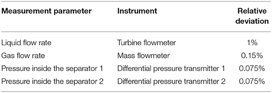
Table 1. Measurement parameters and relative deviation of instruments.
During the experiment, the camera was used to record experimental phenomena of each working condition. By comparing the liquid level with the scale of the scale in the photograph, the accurate liquid level value can be obtained.
In each working condition, in order to ensure the accuracy of the liquid level measurement results, these two liquid level measurement methods were averaged by multiple measurements.
Experimental Results
The Separation Performance of the Separator Under Different Flow Patterns
In previous research, there are many methods for dividing the flow patterns of gas-liquid mixture under inclined conditions. According to the study of Barnea et al. (1980), in the upward inclined pipe, there are three flow patterns: dispersed bubble flow, intermittent flow, and annular flow under different gas and liquid flow rates couples. In this research, the gas volume fraction β was calculated as follows:
where Vg is the gas flow rate and Vl is the water flow rate (m3/h).
The separation performance of the separator under different flow patterns are shown in Figure 5. Under the condition of dispersed bubble flow, the gas is dispersed in the continuously liquid in the form of small babbles with different diameters and the flow state of two phases fluid is stable relatively. In Figure 5A, it can be seen that the gas and liquid mixture was separated directly with the influence of gravity after entering the gravity separation chamber.
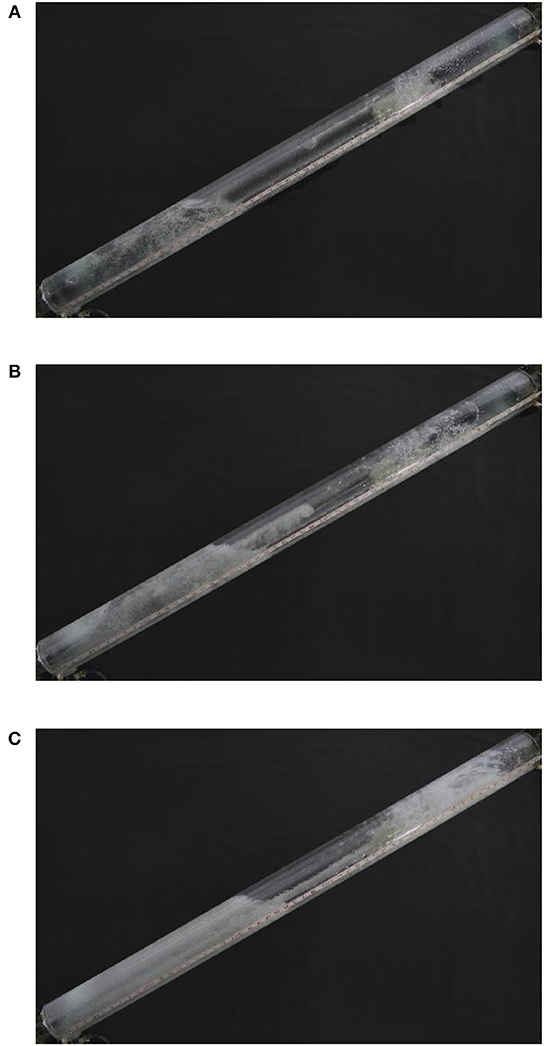
Figure 5. The performance of the separator under different flows. (A) Dispersed bubble flow (Vl = 3.33 m3/h, β = 5%). (B) Intermittent flow (Vl = 3.33 m3/h, β = 50%). (C) Intermittent flow (Vl = 3.33 m3/h, β = 90%).
With the increase of gas volume fraction, the flow pattern of gas liquid mixture is changed from the dispersed bubble flow to the intermittent flow and the flow instability of the gas-liquid mixture is increased gradually. Under the condition of intermittent flow, as shown in Figure 5B, the gas-liquid mixture enters the gravity separation chamber after a preliminary separation in the opening section. Due to the difference in inner diameter of inner cylinder and outer cylinder, the oscillation of the gas-water mixture in inner cylinder does not continue to be transmitted after entering the gravity separation chamber. After entering the gravity separation chamber, with the influence of centrifugal force, the liquid is thrown onto the inner wall of the outer cylinder, and then falls back under the action of gravity. At the same time, the gas leaves the separator through the gas outlet of the separator, and then completes the entire separation process. There are two main functions for throwing the liquid into the inner wall of the outer cylinder. First of all, under the unstable flow pattern, this can avoid the impact height of the liquid in the gravity separator chamber is too high after leaving the inner cylinder, which is beneficial to the improvement of separation performance. On the other hand, this is beneficial to reduce the amount of the liquid droplets entering the gas outlet entrained by gas under the condition of high gas volume fraction.
When the gas volume fraction is further increased, the oscillations inside the inner cylinder are intensified. In Figure 5C, it can be found that the state of the gas-liquid mixture in the separator is similar to that in Figure 5B. It should be noted that due to the influence of gas-liquid mixture oscillation and gas phase entrainment, the liquid can reach the top of the outer cylinder. According to experimental observations, the design of the baffle plate and the extension of the air outlet prevents the liquid drops entering the gas outlet effectively.
According to the above experimental results, it can be found that this new kind of gas-liquid separator can maintain high efficient separation of gas-liquid mixtures under different flow patterns, especially unstable flow patterns, by the combination of gravity separation and centrifugal separation.
Critical Liquid Levels of the Separator
In order to ensure the separation efficiency of the separator, the liquid level between the inner cylinder and the outer cylinder must be maintained at a certain height. Experimental phenomena of the separator when the liquid level is too low and too high are shown in Figure 6. In Figure 6A, it can be observed that due to the fall of the liquid, there is a large amount of bubbles below the liquid level between the inner cylinder and the outer cylinder, which will leave the separator with the liquid through the liquid outlet, resulting in a decrease in separation efficiency. On the other hand, as shown in Figure 6B, when the liquid level inside the separator is too high, a large number of liquid droplets will leave the separator through the gas outlet, which also lead to the reduction of separation efficiency.
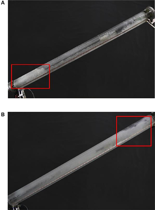
Figure 6. The performance of separator under unreasonable liquid levels. (A) Low liquid level. (B) High liquid level.
Therefore, the liquid level between the inner cylinder and the outer cylinder must be maintained at a certain height in order to ensure the separation efficiency of the separator. In this research, the upper critical liquid level (Lu) and the lower critical liquid level (Ll) were defined, and their definitions are as fellows.
The Lower Critical Liquid Level (Ll)
Under the premise of maintaining the separation efficiency at a high level, the lowest value of liquid level inside the separator.
The Upper Critical Liquid Level (Lu)
Under the premise of maintaining the separation efficiency at a high level, the highest value of liquid level inside the separator. This liquid level value is set near the opening section conservatively.
Through a series of experiments, the upper critical liquid level (Lu) and the lower critical liquid level (Ll) of the separator were determined under our experimental conditions. The experimental result is displayed in Figure 7. In the actual application, to ensure the separation efficiency of the separator, the liquid level inside the separator should be maintained between the upper critical and lower critical liquid levels (Lu > L > Ll). According to the experimental results, when the liquid level is maintained between the upper and lower critical levels, the separation of the separator can be considered as 100%.
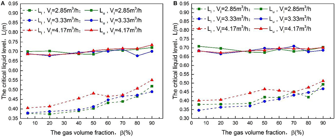
Figure 7. The critical liquid level of the separator. (A) Measured by ruler. (B) Measured by differential pressure transmitter.
As shown in Figure 7, with the increase of gas volume fraction, the upper critical liquid level is changed slightly, while the lower critical liquid level is increased significantly. On the other hand, under the same gas volume fraction, the lower critical liquid level is increased with the increase of liquid flow rate. The reason for basically unchanged in the upper critical liquid level is due to its own definition. The upper critical liquid level is set near the opening section. With the increase of gas volume fraction, the oscillation of the gas-liquid mixture is gradually increased. Affected by the oscillation of the gas-liquid mixture, more and more gas is dispersed in the liquid in the form of bubbles with small diameter. In addition, these small bubbles were carried by the liquid into the annular chamber between the inner and outer cylinders. The smaller the bubble diameter, the better its following ability (Manica et al., 2016). In order to avoid excessive bubbles leaving the separator with the liquid from the liquid outlet, the lower critical liquid level is increased with the increase of gas volume fraction. Under the same gas volume fraction, with the increase of liquid flow rate, when the liquid falls from the gravity separation chamber to the annular chamber between the inner and outer cylinders, the disturbance caused by it can be transmitted to a deeper position. As a result, the lower critical liquid level is increased to a certain extent to avoid excessive bubbles leaving the separator with the liquid from the liquid outlet.
As shown in Figure 8, it can be found that the liquid level value measured by ruler is larger than that of differential pressure transmitter slightly. In addition, with the increase of gas volume fraction, the difference between the critical liquid levels obtained by the two methods is increased gradually. This is mainly due to the liquid density was used as the density of the fluid inside the annular chamber between the inner and outer cylinders, when calculating the liquid level based on the measured data of the differential pressure transmitter. According to the above discussion, it can be known that the fluid inside the annular chamber between the inner and outer cylinders contains some bubbles, and the number of bubbles gradually increases with the increase of gas volume fraction. The true density of the fluid inside the annular chamber is less than the density of the liquid and this true density is decreased with the increase of gas volume fraction. As a result, with the increase of gas volume fraction, the difference between the critical liquid levels obtained by the two methods is increased gradually.
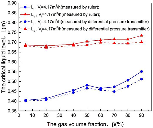
Figure 8. The comparison of critical liquid levels measured by ruler and differential pressure transmitter.
Conclusions
In this research, a new kind of gas-liquid separator was proposed for the separation of gas-liquid mixture under different flow patterns. To test the performance of the separator, an inclined experimental system with an angle of 60 degrees from the vertical was established. The experimental results show that the separator can meet the requirements of high efficiency gas-liquid separation under different patterns, especially under unstable flow patterns.
The liquid level inside the separator is an important factor affecting the performance of the separator. To ensure the separation performance of the separator, the liquid level between the inner cylinder and the outer cylinder must be maintained between the lower critical liquid level (Ll) and the upper critical liquid level (Lu).
Data Availability
All datasets generated for this study are included in the manuscript/supplementary files.
Author Contributions
CZ and WY analyzed the experimental results and wrote the paper. GW, XZ, and AL assisted in experimental work and dealt with the experimental data. CY and GF gave the guideline of this research and modified the language of the manuscript.
Conflict of Interest Statement
The authors declare that the research was conducted in the absence of any commercial or financial relationships that could be construed as a potential conflict of interest.
Acknowledgments
The authors greatly appreciate support from the National Natural Science Foundation of China (Grant No. 11875117) and support from the Fundamental Research Funds for Central University of Ministry of Education of China (HEUCF181505, 3072019CF1506).
References
Bai, Z., Wang, H., and Tu, S. (2011). Oil–water separation using hydrocyclones enhanced by air bubbles. Chem. Eng. Res. Des. 89, 55–59. doi: 10.1016/j.cherd.2010.04.012
Barnea, D., Shoham, O., and Taitel, Y. (1980). Flow pattern transition for gas-liquid flow in horizontaland inclined pipes. Int. J. Multiphase Flow 6, 217–225. doi: 10.1016/0301-9322(80)90012-9
Cai, B., Wang, J., Sun, L., Zhang, N., and Yan, C. (2014). Experimental study and numerical optimization on a vane-type separator for bubble separation in TMSR. Prog. Nucl. Energy 74, 1–13. doi: 10.1016/j.pnucene.2014.02.007
Dixit, P., Tiwari, R., Mukherjee, A. K., and Banerjee, P. K. (2015). Application of response surface methodology for modeling and optimization of spiral separator for processing of iron ore slime. Powder Technol. 275, 105–112. doi: 10.1016/j.powtec.2015.01.068
Funahashi, H., Hayashi, K., Hosokawa, S., and Tomiyama, A. (2016). Study on two-phase swirling flows in a gas–liquid separator with three pick-off rings. Nucl. Eng. Des. 308, 205–213. doi: 10.1016/j.nucengdes.2016.08.030
Hreiz, R., Gentric, C., Midoux, N., Lainé, R., and Fünfschilling, D. (2014a). Hydrodynamics and velocity measurements in gas–liquid swirling flows in cylindrical cyclones. Chem. Eng. Res. Des. 92, 2231–2246. doi: 10.1016/j.cherd.2014.02.029
Hreiz, R., Lainé, R., Wu, J., Lemaitre, C., Gentric, C., and Fünfschilling, D. (2014b). On the effect of the nozzle design on the performances of gas–liquid cylindrical cyclone separators. Int. J. Multiphase Flow 58, 15–26. doi: 10.1016/j.ijmultiphaseflow.2013.08.006
Kataoka, H., Shinkai, Y., and Tomiyama, A. (2009). Pressure drop in two-phase swirling flow in a steam separator. J. Power Energy Syst. 3, 382–392. doi: 10.1299/jpes.3.382
Manica, R., Klaseboer, E., and Chan, D. Y. C. (2016). The hydrodynamics of bubble rise and impact with solid surfaces. Adv. Colloid Interface Sci. 235, 214–232. doi: 10.1016/j.cis.2016.06.010
Mao, F., Tian, R., Chen, Y., Chen, B., Wang, B., and Sun, L. (2018). Re-entrainment in and optimization of a vane mist eliminator. Ann. Nucl. Energy 120, 656–665. doi: 10.1016/j.anucene.2018.06.011
Matsubayashi, T., Katono, K., Hayashi, K., and Tomiyama, A. (2012). Effects of swirler shape on swirling annular flow in a gas–liquid separator. Nucl. Eng. Des. 249, 63–70. doi: 10.1016/j.nucengdes.2011.05.036
Nana, Z., Changqi, Y., and Licheng, S. (2013). Experimental study of a gas separator for msr gas removal system. In: International Conference on Nuclear Engineering,ICONE21. Chengdu.
Nieuwstadt, F. T. M., and Dirkzwager, M. (1995). A fluid mechanics model for an axial cyclone separator. Ind. Eng. Chem. Res. 34, 3399–3404. doi: 10.1021/ie00037a027
Shi, S., Xu, J., Sun, H., Zhang, J., Li, D., and Wu, Y. (2012). Experimental study of a vane-type pipe separator for oil–water separation. Chem. Eng. Res. Des. 90, 1652–1659. doi: 10.1016/j.cherd.2012.02.007
Taitel, Y., Bornea, D., and Dukler, E. (1980). Modelling flow pattern transitions for steady upward gas-liquid flow in vertical tubes. Aiche J. 26, 345–354. doi: 10.1002/aic.690260304
Xiong, Z., Lu, M., Li, Y., Gu, H., and Cheng, X. (2013). Effects of the slots on the performance of swirl-vane separator. Nucl. Eng. Des. 265, 13–18. doi: 10.1016/j.nucengdes.2013.08.050
Keywords: gas-liquid separation, critical liquid level, different flow patterns, unstable flow patterns, experimental study
Citation: Zheng C, Yang W, Wang G, Fan G, Yan C, Zeng X and Liu A (2019) Experimental Study on a New Type of Separator for Gas Liquid Separation. Front. Energy Res. 7:102. doi: 10.3389/fenrg.2019.00102
Received: 22 June 2019; Accepted: 02 September 2019;
Published: 13 September 2019.
Edited by:
Wenxi Tian, Xi'an Jiaotong University, ChinaReviewed by:
Kui Zhang, Xi'an Jiaotong University, ChinaZhenqin Xiong, Shanghai Jiao Tong University, China
Junlian Yin, Shanghai Jiao Tong University, China
Copyright © 2019 Zheng, Yang, Wang, Fan, Yan, Zeng and Liu. This is an open-access article distributed under the terms of the Creative Commons Attribution License (CC BY). The use, distribution or reproduction in other forums is permitted, provided the original author(s) and the copyright owner(s) are credited and that the original publication in this journal is cited, in accordance with accepted academic practice. No use, distribution or reproduction is permitted which does not comply with these terms.
*Correspondence: Chunfeng Zheng, emhlbmdjaGZAY25vb2MuY29tLmNu; Changqi Yan, Y2hhbmdxaV95YW5AMTYzLmNvbQ==