 Guido Francesco Frate
 Lorenzo Ferrari
 Umberto Desideri
- Department of Energy, Systems, Territory, and Construction Engineering (DESTEC), University of Pisa, Largo Lucio Lazzarino, Pisa, Italy
The interest toward large-scale electric energy storage technologies is increasing with the large deployment of new renewable capacity. In case of several hours of storage duration, there is no consensus on which technology is the most suited. Several technologies have been recently proposed, among which is pumped thermal electricity storage (PTES), which is a technology based on the idea of storing electrical energy as heat. PTES is usually less efficient than electrochemical batteries, but it is characterized by a lower cost per kilowatt hour, which could make it a suitable alternative for applications with long storage duration. In this study, a recently proposed PTES system based on the use of heat pumps and organic Rankine cycles is investigated from a thermo-economic point of view. The system is powered by both electric and low-grade thermal energy, thus taking advantage of waste heat to increase the electric performance. As the system design both affects efficiency and cost, a trade-off must be found. In this study, this task was performed by means of a multi-objective optimization approach. The relation between electrical round-trip efficiency and system cost is analyzed, and the impact of several design specifications such as boundary conditions, nominal power rating, and storage duration is discussed. Finally, the results are generalized by defining some cost scaling correlations. Large-size configurations (5 MW of charging power for 8 h of storage) may achieve equipment purchasing costs as low as 140 €/kWh and 2,300 €/kW, with an electrical round-trip efficiency of 0.6. These results show that the investigated technology may be suitable in the context of large-scale and long-duration energy storage.
Introduction
Carnot batteries (CBs) is the term that is used to define several different technologies to store electrical energy as thermal energy, which is then used again to generate power. Among the main CB technologies, the following were defined: pumped thermal electricity storage (PTES) (Frate et al., 2017a), also known as compressed heat energy storage (Steinmann, 2014), and liquid air energy storage (LAES) (Morgan et al., 2015). In CBs, the charge phase may be performed by converting electric energy into heat either with different heat pump technologies or with electric heaters. In this way, electrical energy is stored as sensible or latent heat. The discharge phase may be performed with several different heat engine technologies, mainly based on Rankine or Brayton cycles (Benato and Stoppato, 2018b). The basic CB layout includes both hot and cold reservoirs, which are used to store the thermal energy. However, in several advanced configurations, the basic layout is modified, and one of the two reservoirs is eliminated, by using the environment or alternative heat sources and sinks as heat reservoirs (Dumont et al., 2019).
The interest in CBs is due to the fact that they could be an alternative to pumped hydro energy storage (PHES) and to compressed air energy storage (CAES), which are considered as the state-of-the-art technologies for large-scale and long-duration energy storage. CBs are based on well-established technologies such as heat exchangers, thermal tanks, pumps, compressors, expanders, and turbines. CBs are suited for large-size electrical storage applications (Georgiou et al., 2018) since all the major components of the systems are available in different sizes and can be scaled up easily, if necessary. Furthermore, CBs do not suffer from geographical limitations that strongly affect the locations suited for PHES and CAES. In turn, CBs may have lower round-trip efficiencies and higher specific costs if compared to PHES and CAES (Benato and Stoppato, 2018b). The most studied technology in the field of CBs is LAES, but PTES is quickly gaining popularity.
PTES technologies may be divided into two groups. The first group is based on Brayton cycles (direct and inverse) using either dynamic (Desrues et al., 2010) or volumetric machineries (Howes, 2012). In Brayton PTES, the most common working fluid is argon (Wang et al., 2019), and the systems are mostly based on sensible heat storage, either solid (Benato, 2017) or liquid (molten salts) (Laughlin, 2017). In the literature, alternative configurations may be found (Benato and Stoppato, 2018a), where the integration of resistive heaters in the Brayton system is analyzed.
The second group is based on Rankine cycles (direct and inverse). Rankine PTES may have some advantages over the Brayton counterpart, namely, higher energy density, due to the possibility of efficiently using latent heat storage, and lower operating temperatures. Brayton systems that operate up to 1,000°C have been proposed (Desrues et al., 2010), but more realistic estimates set the maximum operating temperature at around 500°C (Howes, 2012; McTigue et al., 2015). On the other hand, Rankine PTES is most often designed to operate under 200°C (Morandin et al., 2012a,b; Frate et al., 2017a), thus reducing safety and material compatibility issues. Despite the differences, Rankine and Brayton PTES may achieve similar efficiencies: 60–65% for Rankine PTES is claimed in Morandin et al. (2012a,b) and Kim et al. (2013), and similar figures are claimed for the Brayton PTES by Desrues et al. (2010) and Laughlin (2017).
Rankine PTES may use different cycle configurations. In Kim et al. (2013), nearly isothermal compression and expansion are introduced by means of liquid piston compressors and expanders. Several different thermal storage technologies can be found in the literature: one-tank thermocline sensible heat storage (Staub et al., 2018), two-tanks sensible heat storage (Frate et al., 2020), several-tanks in series sensible heat storage (Morandin et al., 2012a,b), hybrid sensible/latent heat storage (Jockenhöfer et al., 2018; Steinmann et al., 2019), purely latent heat storage (Frate et al., 2017a), and underground geothermal heat storage (Ayachi et al., 2016).
Many different working fluids were proposed in the literature: trans-critical CO2 Rankine cycles (Morandin et al., 2012a,b), cascaded NH3/water vapor compression heat pump (VCHP) and water steam Rankine cycle (Steinmann, 2014), and VCHPs and organic Rankine cycles (ORCs) (Frate et al., 2017a,b, 2020; Roskosch and Atakan, 2017; Jockenhöfer et al., 2018).
Due to the lower operating temperatures, Rankine PTES has the unique feature of being able to be powered also by waste or low-grade external heat sources. Due to the higher operating temperatures, this may be impossible in Brayton systems. This integration with additional thermal energy inputs, called thermal integration (TI), was proposed by Steinmann (2014, 2017) and was analyzed in depth by Frate et al. (2017a,b), and it may result in a higher energy production during discharge and thus in improved performance. A PTES with thermal integration is called TI-PTES.
A detailed mapping of TI-PTES performance was performed by Dumont et al. (2019), and several other authors investigated the TI potentiality (e.g., Jockenhöfer et al., 2018; Staub et al., 2018; Steinmann et al., 2019).
By using TI, the additional heat is not stored directly in the thermal reservoir. The idea followed here and in the cited studies is to decouple the charge and discharge cycle temperature levels. This is done with a low-grade heat source (Tsrc ≤ 80°C) which powers the HP evaporator during the electrical energy conversion into heat (charge phase). The thermal energy is upgraded by the HP and stored in the hot reservoir. Due to the operating temperature level, especially designed high temperature VCHPs (HT-VCHPs) must be used. HT-VCHPs are growing in popularity for waste heat recovery purposes, and some commercial applications may already be found (Arpagaus et al., 2018). This means that the TI-PTESs based on HT-VCHP and ORC could be a storage system with very high TRL as of today.
Due to TI use, the system may lose one of the two thermal reservoirs. In this and in previous studies by the authors (Frate et al., 2017a,b, 2020), the lost reservoir is the cold one. However, the opposite may be done, as discussed in Dumont et al. (2019) and in Peterson (2011), where an additional heat source is used to replace the hot reservoir while the cold one is maintained. As demonstrated by Dumont et al. (2019), this second option is always worse from a thermodynamic point of view, but it may be preferred for practical reasons (e.g., easier use of latent heat storage, in the case of ice use).
Besides the electrical round-trip efficiency (i.e., the ratio between discharged and charged energy), which is crucial, many other parameters can be used to characterize the performance of an electrical energy storage. One of the most important is the cost. Efficiency and cost must be considered at the same time for electric storage because they both deeply affect the storage economic performance. Recent studies demonstrated that less efficient, but cheaper, technologies may achieve better overall economic performance than the more expensive and more efficient technologies. This is especially true when large capacities are considered (Zakeri and Syri, 2015; Smallbone et al., 2017; Georgiou et al., 2018; Frate et al., 2019b). For grid-scale applications, long storage durations (higher or equal to 4 h) are often targeted, so the cost per kilowatt hour becomes the most influential parameter. This is the reason why CAES and CBs are often proposed as an alternative to PHES instead of electrochemical batteries, which may feature not only unmatched performance but also much higher costs per kilowatt hour (Zakeri and Syri, 2015; Aneke and Wang, 2016; Frate et al., 2019b).
For CBs, efficiency and cost both depend on the thermodynamic cycle arrangement, which can be designed to find the optimal trade-off between the two. Therefore, to search for an optimal configuration, the design must be formulated as a multi-objective problem. This has been done, to the best of the authors' knowledge, for Rankine PTES systems based on supercritical CO2 cycles (Morandin et al., 2013), and for Brayton PTES systems (Smallbone et al., 2017; Georgiou et al., 2018), but not for TI-PTES systems based on organic fluids. Therefore, there is a knowledge gap on this topic for what concerns TI-PTES applications.
As an original contribution to the research on the PTES topic, a thermo-economic analysis of a TI-PTES system based on HT-VCHP and ORC is proposed in this paper. The analysis is conducted in the multi-objective optimization framework, and the trade-off between efficiency and cost is investigated. The analysis is performed for different power ratings and storage durations, and the effect of the heat source temperature levels is discussed. Furthermore, the impact of each component on the total cost is investigated. As it resulted, the TI-PTES systems may achieve competitive economic performance. For an easier exploitation of paper results in economic scenario analyses, cost scaling rules were defined.
Methodology
System Layout
In the investigated system, the charge phase uses a HT-VCHP, whereas the discharge phase uses an ORC.
During the charge phase, the HT-VCHP absorbs electrical energy to move the heat from the heat source to the thermal energy storage (TES). Therefore, the electrical input is converted into thermal energy and stored together with the thermal input from the heat source. In the TES, the energy is conserved for the required time, waiting for discharge. In the meantime, the TES energy content is slightly reduced due to thermal losses. During the discharge phase, the ORC uses, as an input, the thermal energy stored in the TES. The stored thermal energy is thus converted by the ORC to produce the TI-PTES electrical output. The residual thermal energy at the ORC condenser is rejected into the environment. According to the above-mentioned operating principles, the TI-PTES is a hybrid thermal and electrical energy storage, which is powered by both thermal and electrical energy, and it gives back electrical energy. A detailed description of the energy flow rates between the TI-PTES subsystems (HT-VCHP,TES, and ORC) and the related calculations may be found in Frate et al. (2017a, 2020).
As for the TES, a two-reservoir sensible heat storage is used, even though different TES technologies may be used. A two-reservoir TES represents the simplest solution from the design and control points of view. Compared to latent heat storage, it does not impose any set temperature value in the design phase. Furthermore, it guarantees almost constant charge and discharge temperature profiles, differently from one-tank solutions where thermocline occurs due to mixing. Sensible heat TESs may feature energy density values lower than latent heat storage ones. However, it is unclear if reliable and durable latent heat storages are currently available in the investigated temperature range (100–180°C) (Zalba et al., 2003; Reddy et al., 2018).
In the investigated system, HT-VCHP and ORC are internally regenerated, which is a standard in stand-alone applications (Arpagaus et al., 2018; Braimakis and Karellas, 2018). The resulting layout has been already investigated from the thermodynamic point of view in previous studies (Frate et al., 2020), and it can be considered as a standard for TI-PTES systems based on organic fluids. More advanced architectures may be found in literature (as in Staub et al., 2018; Dumont et al., 2019), but here only the standard one is investigated for the sake of simplicity. The investigated TI-PTES layout is reported in Figure 1.
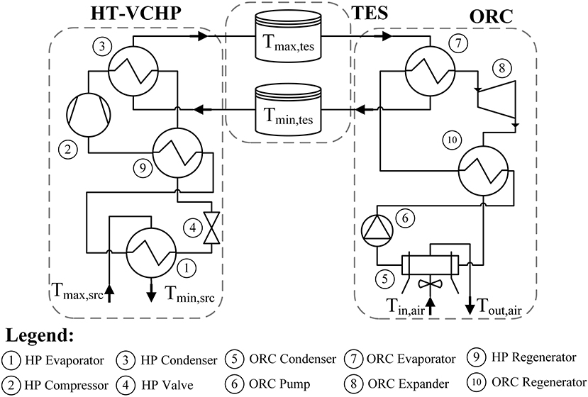
Figure 1. Investigated system layout.
Modeling Hypotheses
HT-VCHP, ORC, and TES performance is affected by some parameters which are assumed to be fixed in the design. This approach is common for techno-economic optimization studies (e.g., see Song et al., 2020) in order to reduce the problem complexity while also maintaining a realistic system description. The fixed parameters here include heat source temperatures, compressor and turbine isentropic efficiencies, minimum heat exchanger approach points, HT-VCHP or ORC minimum pressure level, etc. The related numerical values are reported in Tables 1–3 for the HT-VCHP, the ORC and the TES, respectively. Some of these parameters may have a direct impact on the performance (e.g., isentropic efficiencies), whereas others represent technical constraints, which must be considered to provide a realistic system representation. This is the case of Tmax,hp, pmin,hp, and pmin,orc, which set the boundary for system temperature and pressure design levels. For example, Tmax,hp sets the maximum compressor discharge temperature to 180°C because lubricant oil degradation may occur at higher temperatures (Jensen et al., 2015; Ommen et al., 2015), although oil-free compressors could be used. In this case, the maximum compressor discharge temperature could reach 200°C since several HT-VCHP working fluids start to decompose over such temperatures (Frate et al., 2019a).
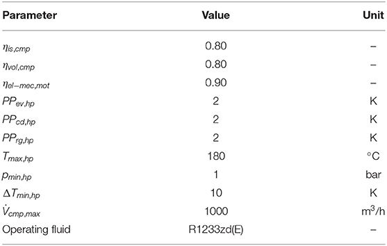
Table 1. HT-VCHP technical and operational parameters.
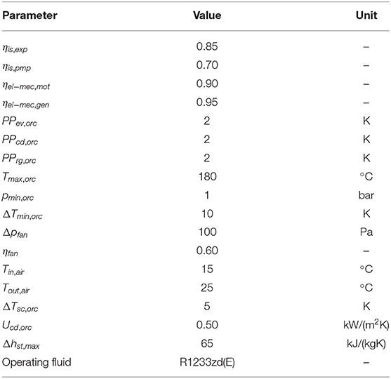
Table 2. ORC technical and operational parameters.
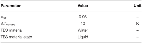
Table 3. TES technical and operational parameters.
Heat exchanger pinch points limit the minimum temperature differences in the heat exchanger that may be assumed in the design. However, higher temperature differences may be selected during design optimization to reduce the equipment cost.
As far as pmin,hp and pmin,orc are concerned, 1 bar is assumed as a minimum to avoid air infiltration (Quoilin et al., 2013).
In the ORC, an air condenser is assumed. In this case, the fan consumption must be cut out from the gross ORC power output. The fan consumption depends on the air side pressure drop (Δpfan) and on the fan “efficiency” ηfan, which accounts for the whole conversion between electric and mechanical power transmitted to the air.
Other relevant modeling assumptions are:
• pressure drop in all the heat exchangers are neglected;
• only the steady-state operation is analyzed;
• the environmental temperature Tin,air = 15°C;
• the air temperature glide across the ORC condenser is fixed and ΔTair = Tout,air – Tin,air = 10 K;
• the heat source maximum temperature, i. e., the temperature at which the heat is provided to the HT-VCHP evaporator, is assumed to vary between Tmax,src = 80°C and Tmax,src = 60°C;
• the heat source temperature glide across the HT-VCHP evaporator is fixed and ΔTsrc = Tout,src – Tin,src = 10 K;
• TES losses are considered through a fixed efficiency ηtes = 0.95, which accounts for both thermal losses and TES circulation pump parasitic consumption;
• thermal energy input from the heat source is considered as readily available. As detailed in Frate et al. (2017a, 2020), the low-temperature (i.e., low-grade) thermal energy used by the TI-PTES could be provided by several different heat sources: low concentration solar collectors, low enthalpy geothermal resources, and industrial waste heat. If solar and geothermal resources are considered, to disregard the economic cost associated with the source realization, it must be assumed that the TI-PTES is installed with an already existing solar or geothermal plant. Therefore, the TI-PTES cost resulting from this analysis must not be used for a stand-alone plant if solar or geothermal applications are considered. For a stand-alone configuration, the solar collectors and geothermal wells cost must be included. In this case, the analysis may provide useful economic insights for what concerns the electrical energy storage part of the system. As for the industrial waste heat exploitation, several industrial sectors may provide abundant heat at low temperatures. Forman et al. (2016) report that around 40% of industrial waste heat is at temperatures lower than 100°C. This share may be up to 80% in the electricity generation sector. Brückner et al. (2015) point out that 50% of process heat in food and tobacco industries and 25% of process heat in pulp and paper and in chemical industries are below 100°C. Hence, these processes reject heat at a temperature potentially suited for TI-PTES applications. Potential low-grade heat vectors are cooling water from furnaces, internal combustion engines, compressors or process steam condensate as well as exhaust gases (Brückner et al., 2015). Of course, not all these heat may be recovered, and in some cases the recovery may cause undesired side effects (e.g., exhaust gases acidic condensation). For these reasons, the actual waste heat availability in the desired temperature range is difficult to estimate. In all cases, additional costs due to the waste heat recovery system integration into the industrial plant may be borne. These “integration costs” are traditionally not included in the system purchased equipment cost (PEC) but are considered in the total investment cost (TIC) by means of a PEC multiplicative factor (Lemmens, 2016). According to this, the same approach is followed in the analysis.
HT-VCHP and ORC Working Fluid Choice
HT-VCHP and ORC performance and cost are deeply affected by the working fluid choice (Chen et al., 2010; Arpagaus et al., 2018; Frate et al., 2019a). This is reflected on the TI-PTES, whose performance is affected by the working fluid pair combination (Frate et al., 2017a,b, 2020). Several authors investigated the TI-PTES performance with different operating fluids, often using the same fluid for both HT-VCHP and ORC. TI-PTES performance with R365mfc is investigated in Staub et al. (2018), butene in Jockenhöfer et al. (2018) and Steinmann et al. (2019), and R1233zd(E) and R1234yf in Dumont et al. (2019). An extensive comparison between 17 fluids is performed in Frate et al. (2017a), and R1233zd(E) was found to be the one with the highest efficiency among those with low GWP. In Frate et al. (2020), eight fluids [cyclopentane, pentane, R1233zd(E), R1224yd(Z), R245fa, R1336mzz(Z), R365mfc, and R1234ze(Z)] and their pairwise combinations were investigated. The pair with the highest electrical round-trip efficiency was the one using cyclopentane in both HT-VCHP and ORC. Nonetheless, it was also found that several other different pairs may achieve comparable performance especially if the design is not fixed and can be optimized case by case.
Here, R1233zd(E) is selected as the TI-PTES working fluid. The choice is based on the results reported in Frate et al. (2017a,b) and Dumont et al. (2019) which identify R1233zd(E) as a promising fluid for TI-PTES applications. As far as the other above-mentioned fluids are concerned, R1233zd(E) is safer than butene and cyclopentane as it is not flammable, and it has lower environmental impact than R365mfc (GWP = 804). In addition to this, R1233zd(E) is one of the best fluids for HT-VCHP, from both the efficiency and the cost points of view. As a matter of fact, HT-VCHP cost is strongly affected by the compressor cost, which mostly depends on the refrigerant volumetric flow rates. According to Arpagaus et al. (2018) and Frate et al. (2019a), R1233zd(E) is characterized by a good compromise between the HP coefficient of performance (COP) and low volumetric flow rates. Therefore, R1233zd(E) is not only a good fluid from a thermodynamic standpoint but may also limit the equipment cost if compared to other fluids. The R1233zd(E) thermophysical properties are reported in Table 4. The fluid properties are evaluated by means of REFPROP v. 10.0 (Lemmon et al., 2018). REFPROP is invoked by means of CoolProp v. 6.3.0 (Bell et al., 2014).
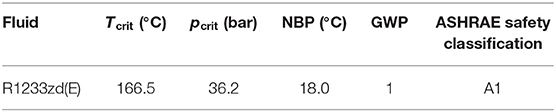
Table 4. R1233zd(E) thermophysical properties.
Performance Parameters
In this analysis, the trade-off between round-trip efficiency and cost is investigated. Therefore, these two parameters must be defined. Based on the TI-PTES subsystem energy balances and by following the same approach outlined in Frate et al. (2017a,b, 2020), the electrical round-trip efficiency ηrt may defined as in Equation (1):
It is worth mentioning that under some circumstances ηrt may be higher than 1 (as demonstrated in Frate et al., 2017a; Dumont et al., 2019). This is because ηrt considers only electrical inputs and outputs, while it disregards the thermal energy input absorbed in the charge phase. Therefore, ηrt is not a global efficiency but only an electrical efficiency. Since the TI-PTES is an electrical energy storage technology, this is the most important performance parameter to consider. This is especially true from the economic point of view as ηrt has a direct impact on the storage economic revenue. However, since a thermal energy input is used, different performance parameters may also be considered, such as energy efficiency, as done in Dumont et al. (2019) and Frate et al. (2020). The trade-off between energy efficiency and ηrt is analyzed in detail elsewhere (Frate et al., 2020); thus, it is not discussed here.
By considering the common definitions of COP and ηorc, the former can be written as in Equation (2):
where Δhcmp,hp and Δhcd,hp are the refrigerant enthalpy differences in HT-VCHP compressor and condenser, respectively. As for ηorc (Equation 3), the net power output is equal to the turbine power output minus the circulation pump and condenser fan consumptions:
where Δhexp,orc, Δhpmp,orc, Δhcd,orc, and Δhev,orc are the refrigerant enthalpy differences in the ORC expander, pump, condenser, and evaporator, respectively. cpair and ρair are the air-specific heat and density, which are averaged between Tout,air and Tin,air.
Besides ηrt, the other relevant parameter is the system cost. The TIC is calculated as the summation of the single component PECs, as in Equation (4):
There is no consensus over the value of the parameter Ktic, which accounts for all the additional costs due to contracting, building, land use, system integration, etc. Ktic depends on whether the system is built from scratch, it is placed in an already used site, it is a repowering of an already existing system, etc. Furthermore, different authors assume different Ktic values for representing the same cost items. Thus, 1.4 is assumed in Astolfi et al. (2014a,b), 4.16 is assumed in Jensen et al. (2015) and Ommen et al. (2015) according to Bejan et al. (1996), and 1.18 is assumed by van Kleef et al. (2019) and Song et al. (2020) based on the recommendations in Turton et al. (2009).
To avoid the uncertainty due to Ktic numerical value, in the design optimization problem the PEC is considered and not the TIC. In this case, even if the considered numerical values are different, the physical meaning of the efficiency and cost trade-off is the same. The components considered in Equation (4) are HT-VCHP evaporator, condenser, regenerator, and compressor; ORC evaporator, condenser, regenerator, pump, turbine, and electric generator; and, finally, TES material and storage volume. For each of these, a cost correlation was used for the PEC estimation, as reported in the next section.
Equipment Cost Functions
For the ORC components, the cost correlations from Astolfi et al. (2014a,b) were used. Since the HT-VCHP heat exchangers share the same technology with the ORC ones, the same cost correlations are used. For the HT-VCHP compressor, a self-derived cost function based on vendor data (Bitzer, 2019) was proposed. For the TES, the cost functions derived from those of Turton et al. (2009) were used.
As it was discussed in Lemmens (2016), the cost model accuracy is suited for first estimation purposes. Therefore, the resulting TI-PTES cost should be regarded as suited for a technology comparison study. However, in case of more specific applications, a more economic assessment should be performed.
For the HT-VCHP evaporator, HT-VCHP condenser, and ORC evaporator, the following cost correlation may be used (PEC in k€):
where U is the heat exchanger global heat transfer coefficient in kW/(m2K), and A is the heat exchanger area in m2. fp accounts for the heat exchanger operating pressure p in bar (Equation 6):
where α1 = −0.00164, α2 = −0.00627 and α3 = −0.0123.
For both HT-VCHP and ORC regenerators, the following cost function may be used (Equation 7):
In Equation (5, 7), since the UA product is the relevant parameter, a direct estimation of U may be avoided. As a matter of fact, UA may be calculated from the heat exchanger number of transfer units (NTU) (Equation 8):
where j defines the heat exchanger side (hot/cold) and (ṁcp)j is the j-th fluid heat capacity rate. If in at least one of the heat exchanger sides a single-phase fluid flows, (ṁcp) is well-defined, and Equation 8 may be used to calculate either NTUj or UA. Here, (ṁcp)j is referred to the sides in which single-phase fluids flow, i.e., ORC evaporator hot side, HT-VCHP condenser cold side, and HT-VCHP evaporator hot side. A heat exchanger where both heating and/or cooling and phase change occur may be approximated with a series of i-th heat exchangers where only one of these processes occurs (VDI, 2010). For a heat exchanger series, the global NTUj is calculated as the summation over the i-th NTUij. Each NTUij may be estimated as a function of the heat exchanger inlet and outlet temperatures and of the fluid heat capacity rate ratio by means of correlations. Different approaches may be found in the literature (ε -NTU, P-NTU, etc.). In this analysis, the P-NTU method from VDI (2010) is used. The related correlations are different according to the heat exchanger fluid arrangement. Here the correlations for shell-and-tube heat exchangers with one shell side pass and two tube side passes (S&T-12) are used (VDI, 2010). It is worth mentioning that the heat exchanger temperature profiles and fluid mass flow rates are defined during each step of the design optimization problem (see section Design Optimization Problem). Therefore, for each TI-PTES design, NTUij may be estimated and, from these, each heat exchanger UA may be calculated.
For the ORC pump, Equation (9) is used:
where Ẇpmp,orc is the ORC pump nominal power input.
For the electric generator, Equation (10) is used:
where Ẇnet,orc is the ORC nominal power output.
For the ORC condenser, Equation (11) is used:
which is calculated by assuming Ucd,orc = 0.5 kW/(m2K).
For the ORC turbine, the following cost function is used (Equation 12):
Nst is the turbine number of stages, estimated by assuming that the maximum enthalpy drop per stage is Δhst,max = 65 kJ/(kgK) (Astolfi et al., 2014a,b). SPlast is the turbine last-stage size parameter, calculated as in Equation (13):
where is the volumetric flow rate at the turbine outlet in m3/s and Δhis is the isentropic enthalpy difference across the turbine last stage.
For the HT-VCHP compressor, the following (Equation 14) was used:
where is the number of compressors that run in parallel, and the function ceil(·) yields the nearest upper integer of its argument. is the total volumetric flow rate at the HT-VCHP regenerator outlet, = 1,000 m3/h is the maximum volumetric flow rate for the single compressor. This value is used because, for higher volumetric flow rates, the cost correlation in Equation (14) may be not accurate. is the volumetric flow rate at the compressor inlet in m3/s. Equation (14) refers to commercial screw compressors, which are suited for large refrigeration applications (Bitzer, 2019). Refrigeration compressor cost must be used since, to the best of the authors' knowledge, no commercial HT-VCHP compressor cost data are available. However, as the compressor technologies for both refrigeration and HT-VCHP applications are the same, the publicly available cost data from vendors may be used. A similar approach was followed in Jensen et al. (2015) and Ommen et al. (2015).
Finally, conditional cost correlations are used for the TES. The correlation parameters vary as a function of the operating pressure. For operating pressures lower than 1.07 bar, atmospheric tanks are used; otherwise, pressurized vessels are used. In both cases, the cost function may be written as in Equation (15):
where Ntnk/vsl = ceil(Vhot/cold,tot / Vtnk/vsl,ax) is the number of tanks/vessels used in parallel. Vhot/cold,tot is the total volume needed to store the prescribed amount of thermal energy. Vhot/cold = Vhot/cold,tot / Nvol is the single hot/cold tank/vessel volume. The Equation (15) coefficients are reported in Table 5 for tanks and vessels, respectively. In case of vessels, γp is written as in Equation (16) (Turton et al., 2009):
where p is the operating pressure in bar and Dvsl is the vessel diameter. For the sake of simplicity, the vessel is assumed to be a cylinder with height equal to diameter, such that Dvsl = (4·Vvsl / π)1/3.
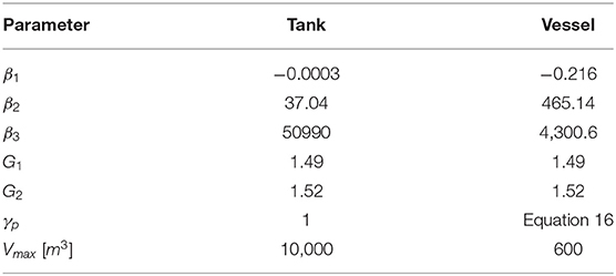
Table 5. TES cost correlation parameters (Equation 15).
For the TES material cost, a simple linear relation was used. Water is assumed as storage material; hence, the cost can be calculated as in Equation (17):
where cwater = 0.0014 €/kg is the water cost for industrial uses (European Enviroment Agency, 2019) and Mwater is the mass of the water required to store the prescribed amount of thermal energy.
Cost correlation results were updated to 2018 by means of the 2018 CEPCI indicator value (i.e., 603), which is the last known value for this parameter. Correlations from Astolfi et al. (2014b) should be updated by considering CEPCI2014 = 576, whereas the correlation from Turton et al. (2009) should be updated by considering CEPCI2001 = 397.
Design Optimization Problem
To explore the trade-off between ηrt and PECtot, a multi-objective optimization approach is followed. The TI-PTES is designed by means of an optimization problem, which adjusts the HT-VCHP, TES, and ORC design parameters to promote one of the two performance parameters.
The TI-PTES design optimization problem is written as in Equation (18):
where x is the vector of the optimization variables, i.e., the design parameters. Φ is the feasible region, and the Rm subset is defined by the problem constraints, which defines the TI-PTES design space. m is the optimization problem dimensionality, i.e., the number of optimization variables, which is 10 in this case. g(x) is the problem objective function. It may be equal to ηrt or PECtot if a single objective design is performed, or it is equal to the following scalar function gsf(x) in the case of a multi-objective problem (Wierzbicki, 1980; Miettinen, 1998) (Equation 19):
where vector function g(x) = [ηrt(x), PECtot(x)] is the objective vector and gref = [, ] is an arbitrary point in the objective space to be achieved. Such point represents the decision maker aspiration level, which can be either feasible or unfeasible. gnad and gid are the Nadir and ideal objective vectors, respectively. Nadir vector represents the worst possible objective combination, whereas the ideal vector represents the best possible objective combination. By using gnad and gid, the numerical scale difference between objectives is eliminated and the optimization problem is well-scaled. By minimizing gsf, the reference point gets “projected” onto the Pareto front and the resulting optimal x* yields one Pareto front point. By varying gref, the Pareto front can be explored.
In order to design the TI-PTES thermodynamic cycles, the following design parameters, i. e., x components, are adjusted:
• Tev,hp, Tcd,hp, ΔTsh,hp, and ΔTsc,hp, which represent the HT-VCHP evaporation and condensation temperatures, the superheating at the regenerator outlet, and the subcooling at condenser outlet;
• Tev,orc, Tcd,orc, and ΔTsh,orc, which represent the ORC evaporation and condensation temperatures and the superheating at the evaporator outlet;
• Tmax,tes and Tmin,tes, which represent the TES maximum and minimum temperatures;
• ΔTrg,orc, the temperature difference between the inlet and the outlet of the ORC regenerator hot side. This variable controls the ORC regeneration degree.
ΔTsc,orc, i.e., the subcooling at the ORC condenser outlet, is assumed, and not optimized, because it is a necessary ORC feature to prevent pump cavitation, but it is usually minimized as it is negative for cycle efficiency. Likewise, there is no need to optimize the HT-VCHP regeneration degree ΔTrg,hp. This is because the HT-VCHP regeneration is used to provide the required superheating at the evaporator outlet. Hence, ΔTrg,hp can be directly calculated from the HT-VCHP regenerator energy balance as a function of ΔTsh,hp.
As far as the feasible region Φ and the constraints are concerned, they are used to make the TI-PTES design realistic and to avoid unphysical and unfeasible configurations. The constraints are formulated as inequalities to be satisfied. The complete list of constraints is not reported here, for the sake of brevity, as it can be found in Frate et al. (2020). However, the constraint purposes may be summarized as follows:
• some constraints are dedicated to the observance of heat exchangers minimum pinch points. This prevent heat transfer with null or negative temperature difference from occurring;
• two constraints guarantee that the HT-VCHP compression and the ORC expansion end with dry vapor;
• some constraints enforce subcritical working conditions to both HT-VCHP and ORC, while some others guarantee that neither maximum allowable temperatures nor minimum allowable pressures are exceeded;
• one constraint guarantees that the ORC power output is non-negative, whereas another one guarantees that the HT-VCHP COP is equal or higher than 1;
• three constraints guarantee that the ORC, the HT-VCHP, and the TES are designed such that Tev,hp < Tcd,hp, Tev,orc > Tcd,orc, and Tmax,tes > Tmin,tes;
• finally, some constraints guarantee that the mass and energy balances are always observed inside, and between, each TI-PTES component.
The optimization problem in Equation 18 was solved with a SQP algorithm, as implemented in MathWorks (2019). In theory, the problem is not differentiable and without any analytical representation. As a matter of fact, to compute objective function, the REFPROP routines are called several times to calculate the required fluid thermophysical properties in each thermodynamic cycle point. Each REFPROP call numerically solves the fluid equation of state. In this case, the problem objective function is black box, which can be numerically evaluated, but it does not have analytical derivatives. Nevertheless, as the SQP solver numerically approximates gradients and hessians, it is possible to solve the problem if it is sufficiently smooth. This is exactly the case due to the general smoothness of the fluid's thermophysical properties. Therefore, the problem is solvable with a gradient-based approach.
However, Equation (18) problem is highly non-linear. Therefore, the solver is likely to be trapped in a local minimum. To try to prevent this from occurring, a multi-start strategy was adopted and each optimization is repeated 20 times, starting from different initial points randomly chosen, and the best result is collected.
It is worth noting that, as a general rule, the same optimization problem may be solved with different algorithmic approaches. Here, as the analysis deals with the system design, and not, for example, with its control, the optimization problem must be solved a limited number of times. In this case, algorithm speed and efficiency are almost irrelevant, whereas reliability (i.e., the ability of consistently finding a satisfactory optimum point) is the most important feature. By experimenting with different algorithmic approaches based on gradients, like SQP or interior point algorithms, or not, like genetic algorithm and generalized pattern search algorithms, SQP was found as the most reliable one for the problem under investigation.
Even though algorithm speed is not a relevant feature in this case, the SQP resulted to be quite fast. Despite that each optimization was repeated 20 times, due to the multi-start strategy, finding a satisfactory Pareto front approximation for one TI-PTES configuration usually took <10 min on a common desktop PC equipped with Matlab v. 2019b.
Investigated Configurations
In order to investigate the trade-off between round-trip efficiency and cost for different TI-PTES configurations, some optimization problem boundary conditions are modified each time. These are the nominal HT-VCHP power input (storage charge power), the storage duration, and the heat source temperature. In this analysis, HT-VCHP power inputs comprising between 500 and 5,000 kWel are analyzed. This is the TI-PTES power range that is investigated in the paper. As for the storage duration, charge and discharge time (τch and τdis) ranging from 4 to 8 h were considered. Charge time and HT-VCHP nominal electric power input may be multiplied to find the storage electric capacity in kWhel. From this, the ORC nominal power output may be determined as in Equation (20):
For the sake of simplicity, in the analysis, τch = τdis for each investigated configuration. Of course, different configurations may be designed, but this must be decided after having identified a case study, which is out of the scope of the present analysis.
As for the heat source, Tin,src values ranging from 60 to 80°C were considered. The investigated configurations are summarized in Table 6.
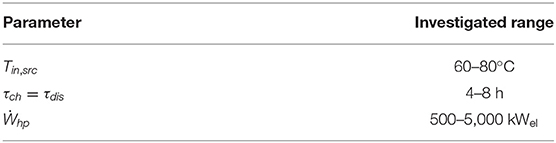
Table 6. Investigated configurations.
Cost Scaling Laws
After having solved the multi-objective optimized design for several different configurations, the PEC may be described as a function of Tin,src, τch, Ẇhp, and ηrt. More details on the functional form choice will be provided in the next section. Here the equations that are used to describe the TI-PTES cost scaling for different configurations are just introduced. Instead of using a single equation for PECtot, two equations are used to describe the TI-PTES power conversion section and energy conservation section PEC, i.e., PECpcs and PECecs. The first accounts for the HT-VCHP and ORC cost, whereas the second accounts for the TES cost.
In both cases, the equation that is fitted to the data is the following one (Equation 21):
where A, B, and C are cubic functions of Tsrc,in, as in Equation (22):
Coefficients ai, bi, and ci must be fitted from data, as well as coefficient d.
In the case of power conversion section PEC, Xpcs = . Otherwise, for the energy conservation section, Xecs = .
Results
The first presented results are those related to Figure 2, where the Pareto fronts resulting from the optimization problem in Equation (18) are reported. Each front corresponds to one Tin,src, τch, and Ẇhp combination. As it resulted, the trade-off between ηrt and PECtot is very strong: the PEC may increase up to five times from minimum to maximum ηrt combinations. In Figure 2, the impact of Tin,src, τch, and Ẇhp on Pareto fronts may be observed. As it resulted, the two most impactful parameters are Tin,src and Ẇhp. Tin,src does not change the PECtot values, but it changes the ηrt values for which they are achieved. Conversely, Ẇhp does not impact the maximum achievable ηrt, but it strongly influences the resulting PECtot as a larger system naturally costs more than the smaller ones.
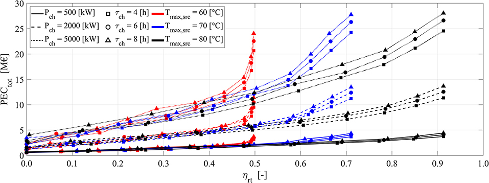
Figure 2. Pareto fronts of electrical round-trip efficiency ηrt and total equipment purchasing cost PECtot. Results are reported for several heat source temperatures Tin,src, several storage duration τch, and system nominal power input Ẇhp.
Since Tin,src controls the maximum achievable ηrt values, it controls also where the Pareto front slope changes, which is where the PEC starts to quickly increase. From these points onwards, each ηrt increase requires higher PEC increases, thus discouraging the adoption of higher efficiency values.
If the configurations with ηrt < 0.5 are considered of no practical interest, then Figure 2 results demonstrate how Tin,src > 60°C should be always adopted. For efficiency values lower than this threshold, e. g., ηrt < 0.4, the PECtot resulted to be independent from Tin,src. This happens because, for such ηrt values, Tin,src does not act anymore as a limitation. In this case, the Tin,src impact becomes negligible and all the configurations start to behave similarly.
The second influential parameter is the TI-PTES nominal charge size Ẇhp. Even though larger systems naturally entail larger costs, Ẇhp does not influence the PECtot linearly. A preliminary estimate suggests that, for Ẇhp between 500 and 2,000 kWel, the PECtot increases with a rate of around 5.3 k€/kWel, whereas for Ẇhp between 2,000 and 5,000 kWel the rate is lower, around 4.7 k€/kWel. This shows that PECtot increases with the size at a sublinear rate, i.e., it follows a power law, as it was anticipated in section Cost Scaling Laws. This is a common feature for systems like HT-VCHP and ORC, and it stems from the non-linearity of the cost correlations in section Design Optimization Problem.
As far as τch is concerned, it has a lower impact on PECtot if compared to Tin,src and Ẇhp. With Tin,src and Ẇhp being equal, higher τch entails higher absolute costs as the storage capacity is increased. However, by doubling the capacity, as was done by passing from τch = 4 h to τch = 8 h, PECtot is not doubled. There are two reasons for this behavior. First, the TES represents only a PECtot part, around one third, as it will be demonstrated hereinafter. Second, PECtes itself does not increase linearly with the stored kWhel, i.e., with the capacity, as the TES cost correlations are not linear with the volume. Conversely, the cost related to TES material follows a linear trend, but this represents a negligible share as it will be demonstrated hereinafter.
In Figure 3, it is demonstrated how the trade-off between ηrt and PECtot is controlled along the Pareto fronts. As it resulted from Figures 3A–C, the ORC evaporation temperature is almost constant over the Pareto front, at least for ηrt > 0.5. To interpret this result, it may be useful to remember that the optimizer can choose between atmospheric tanks and pressurized vessels when the TES is to be designed. Atmospheric tanks have lower costs, but they also limit the TES temperature profile to values lower than 100°C. As a consequence, this limits the ηrt as the ORC must operate with lower evaporation temperatures, thus with a reduced ηorc. On the contrary, with pressurized vessels, the TES temperature can be increased, and the ORC may achieve higher evaporation temperatures and thus higher efficiencies. Therefore, the pressurized vessel configuration has not only higher costs but also higher ηrt values.
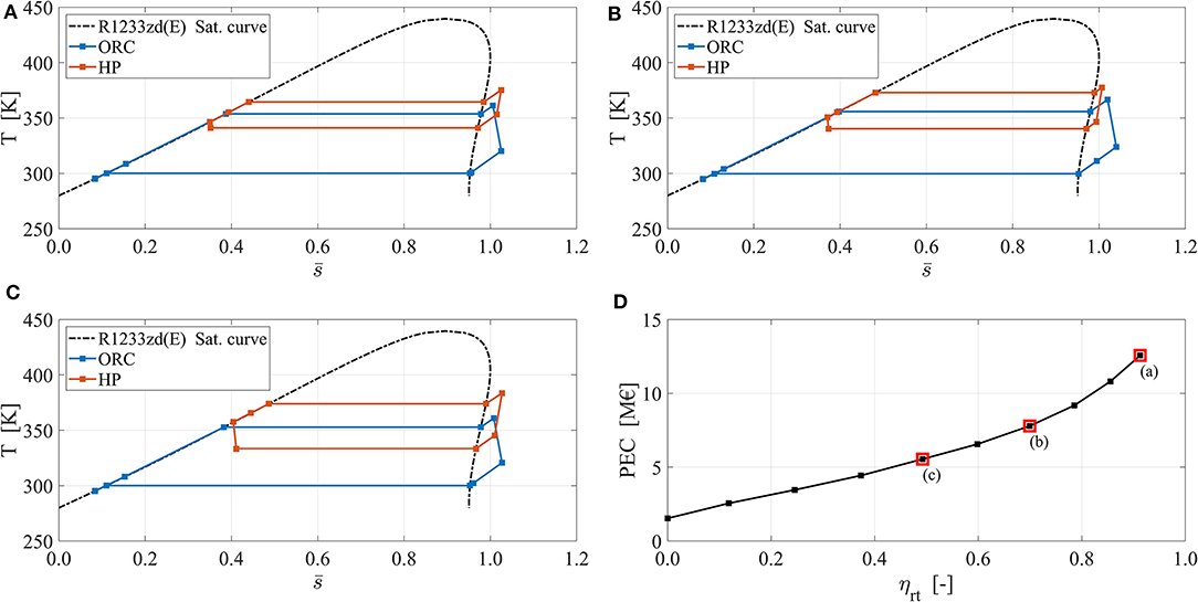
Figure 3. HT-VCHP and ORC thermodynamic cycle arrangements on the temperature–entropy plane. The entropy is normalized as it follows: , where smin and smax are the minimum and the maximum of the entropy achieved over the whole saturation line for T > 280 K. Results are reported for Tin,src = 80°C, τch = 6 h, and Ẇhp. = 2,000 kWel. (A) High efficiency configuration. (B) Medium efficiency configuration. (C) Low efficiency configuration. (D) Position of configurations (A–C) over the Pareto front.
As reported in Figure 3A, the ORC evaporation temperature level is always lower than 100°C, even in the case with maximum ηrt. This demonstrates that the pressurized vessels are never selected by the optimizer, not even in the case of maximum ηrt. It is worth noting that, for maximum ηrt configuration, the PEC has zero relevance on the optimizer outcome; therefore, it would use the pressurized vessels to further increase ηrt if needed. This conclusion is also supported by the ORC evaporation temperature profile reported in Figures 3B,C. As a matter of fact, the only reason for using pressurized vessels is to increase the ORC evaporation temperature. Therefore, it would be meaningless to use them without exploiting this advantage and leaving the ORC evaporation almost constant, as can be found in Figures 3B,C. This confirms that pressurized vessels are never selected. This is a remarkable result since it provides useful design guidelines on the TES and on the ORC. In summary, only atmospheric tanks should be used for the investigated TI-PTES system. This implies that temperatures lower than 100°C must be used in the TES. This also impacts the ORC evaporation temperature, which should be kept constant and as high as it is allowed by the TES temperature profile.
A further implication of this result is that neither TES nor ORC temperature profiles have any role in controlling the trade-off between ηrt and PECtot as they are constant for several different configurations.
As it is demonstrated in Figures 3A–C, the main distinctive feature between the TI-PTES cycle arrangements along the Pareto front is the HT-VCHP temperature lift ΔThp. ΔThp is defined as the difference between the HT-VCHP condensation and evaporation temperatures and it controls the heat pump COP. As it is known, low ΔThp yields high COP and vice versa. From Equation (1), it results that the COP controls ηrt, but how does it control the PECtot? To answer to question, it must be remembered that the COP may be defined in two equivalent ways:
• COP is equal to the ratio between the electric power absorbed by the HT-VCHP (i.e., Ẇhp) and the heat flow rate provided to the TES (i.e., );
• COP is equal to the ratio between the electric energy absorbed by the HT-VCHP (i.e., Ẇhp·τch) and the heat provided to the TES (i.e., ).
Therefore, high COP entails larger heat flow rates and larger amounts of stored heat and vice versa. In this way, the COP impacts the TES volume, the heat exchanger surface areas, and the ORC size. Therefore, high COP entails high ηrt and high cost, whereas low COP entails low ηrt and low cost.
To understand which Pareto front points are represented in Figures 3A–C, please refer to Figure 3D.
In Figures 4A,B, the cost composition for two representative TI-PTES configurations (500 and 5,000 kWel, respectively) is reported and compared.
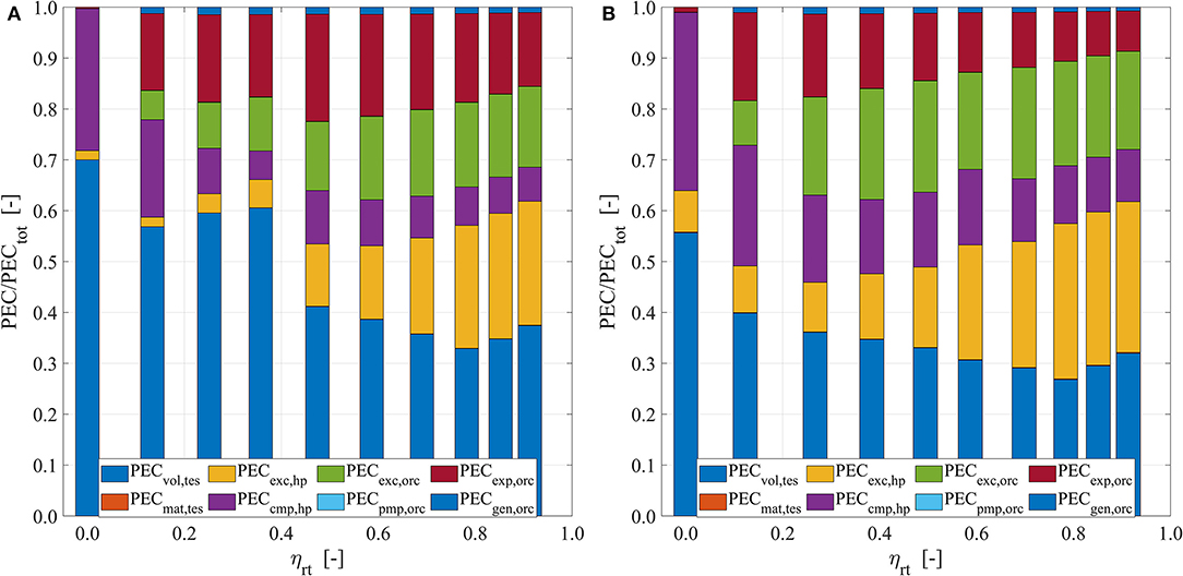
Figure 4. Total cost relative composition. Results are reported for Tin,src = 80°C and τch = 6 h and (A) Ẇhp. = 500 kWel and (B) Ẇhp. = 5,000 kWel.
Previously, how the PECtot is controlled along the Pareto front for ηrt > 0.5 has been discussed. In Figures 4A,B, it is shown how PECtot is minimized for very low ηrt values, i. e., ηrt < 0.2. As can be noted, for ηrt ≈ 0, the ORC cost tends to zero. As the ORC PEC is a function of Ẇorc, the ORC cost may become zero only if Ẇorc = 0. For Equation (20), this may happen only if ηrt = 0. As the minimum HT-VCHP COP is equal to 1, and ηtes is constant in the analysis, for Equation (1), it must be ηorc = 0 to find ηrt = 0. Therefore, for ηrt < 0.2, the ORC is designed in such a way that it artificially reduces the net power output to zero, thus ηorc = 0. In this way, Ẇorc = 0; thus, the ORC-related cost may be set to zero.
Apart from this configuration, it is interesting to analyze how the PEC is distributed for ηrt > 0.5. For Ẇhp = 500 kWel (Figure 4A) and for 0.5 < ηrt < 0.7, the TES is the single costliest subsystem, from 33 to 41% of PECtot, closely followed by the ORC, around 35% of PECtot, and the HT-VCHP represents the remainder. The single costliest component is the ORC turbine, followed by the HT-VCHP and the ORC heat exchangers. In this size range, the HT-VCHP compressor has a very low impact on the cost. Finally, the TES material cost represents a negligible share over the total.
For higher efficiencies, i.e., ηrt > 0.7, the cost is more evenly distributed among HT-VCHP, ORC, and TES, with each subsystem representing around one-third of PECtot. As previously discussed, high efficiency configurations are characterized by higher energy flow rates between the subsystems. Therefore, the heat exchanger specific impact grows such that, besides the TES, the HT-VCHP heat exchangers alone represent the largest PEC share.
In the case of larger nominal power input, i.e., for Ẇhp = 5,000 kWel (Figure 4B), slightly different results may be found. In particular, the TES has a lower impact, and it now represents a lower PECtot share, between 34 and 29%. A similar impact reduction is also shown by the ORC turbine. For larger power ratings, the turbine costs similarly to HT-VCHP compressor, whereas for lower size applications (Figure 4A) the turbine cost is almost three times larger than that of the HT-VCHP compressor. There are two reasons for this. First, the ORC turbine has the best economy of scale among all the TI-PTES components. As a matter of fact, the combined effect of Equation (12, 13) yields a turbine cost that scale with the power output with an exponent equal to 0.55. This is the lowest among the TI-PTES components as most of their cost correlations follow a power law with an exponent comprised between 0.67 and 0.9. Second, the HT-VCHP compressor is limited in size, differently from the ORC turbine; therefore, multiple compressors are used in parallel for large-sized applications. This partially neutralizes the effect of the economy of scale brought by the compressor cost correlation exponent.
Finally, for Ẇhp = 5,000 kWel, the most impactful cost items are the HT-VCHP heat exchangers, which alone accounts for a PEC share even larger than that of TES, especially if high efficiency configurations are considered (ηrt > 0.7). Similarly, the second costliest components are the ORC heat exchangers whose impact is increased, if compared to the case with Ẇhp = 500 kWel. This is explained by observing that the exchangers are among the components with the worst economy of scale, according to Equation (5, 7), which show how the correlation exponent is equal to 0.9.
Finally, as it resulted from Figures 4A,B, for both large- and small-sized configurations, the TES materials are negligible, as well as those of the ORC pump and the electric generator.
In Figures 5A,B, the results related to PECecs and PECpcs may be found. To get rid of the differences in size, the results are reported in relative terms, i.e., in €/kWh and in €/kW. PECrel,ecs is defined as the ratio between PECtes, i.e., the PEC of TES material and tanks, and the storage electric capacity in kilowatt hour. Similarly, PECrel,pcs is defined as the ratio between the summation of the HT-VCHP and ORC PEC and the TI-PTES charge power rating in kilowatt. It is useful to divide PECtot into power- and capacity-related costs as this may provide an easier generalization of the results. As a matter of fact, for an electric storage technology like TI-PTES, the capacity and the power rating may be designed independently, differently from what happens for batteries. Therefore, it is useful to characterize power- and capacity-related costs independently.
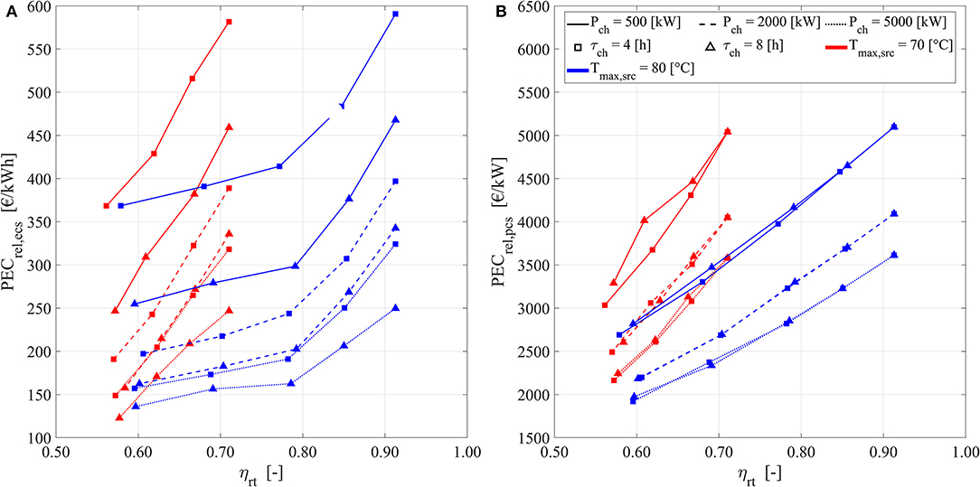
Figure 5. Relative costs in €/kW and €/kWh as a function of storage size, duration, and heat source temperature values. (A) Relative capacity-related cost €/kWh. (B) Relative power-related cost €/kW.
From Figure 5A, it may be noted how PECrel,ecs decreases as the storage capacity increases. This is expected as the TES cost correlation are non-linear, and they benefit from the economy of scale effects. The specific cost decrement is not constant with the size. As the capacity increases, the rate of the specific cost decrement decreases. This behavior is typical of a power law relation and this justifies the functional form chosen in section Cost Scaling Laws for the cost scaling law. A similar conclusion may be drawn also for PECrel,pcs based on the results in Figure 5B. Here the specific PEC decreases, while the TI-PTES nominal power input increases. As it is expected, the power conversion section PEC is almost insensitive to storage duration, i.e., to τch, as the HT-VCHP and the ORC size may be designed independently from the TES size.
In analogy with what is concluded for PECrel,ecs, a power law relation is suited also for describing PECrel,pcs. As it resulted from Figure 5B, by moving from low to high power ratings, the PECrel,pcs decreases at a lower rate.
Both PECrel,ecs and PECrel,pcs resulted to be affected by the heat source temperature Tin,src in a similar way to that described for PECtot in Figure 1. Therefore, Tin,src moves toward higher, or lower, ηrt the point in which the PEC is maximized, while the actual PECtot values are practically unchanged. To consider this, the scaling laws in section Cost Scaling Laws are formulated to represent the PEC/ηrt relation resulting from Figures 5A,B. To do this, a quadratic polynomial function is used, but the parameters of such function are modified by the function of Tin,src.
The resulting cost scaling laws can describe the TI-PTES PECecs and PECpcs with satisfactory accuracy, as it is shown in Figures 6A,B where the fit results are reported. As it resulted, the cost scaling laws defined in section Cost Scaling Laws provide cost predictions which are, for the vast majority, within a ±10% relative error band from the ideal model. Such ideal model is the fictious model that would yield perfect predictions for any set of input data.
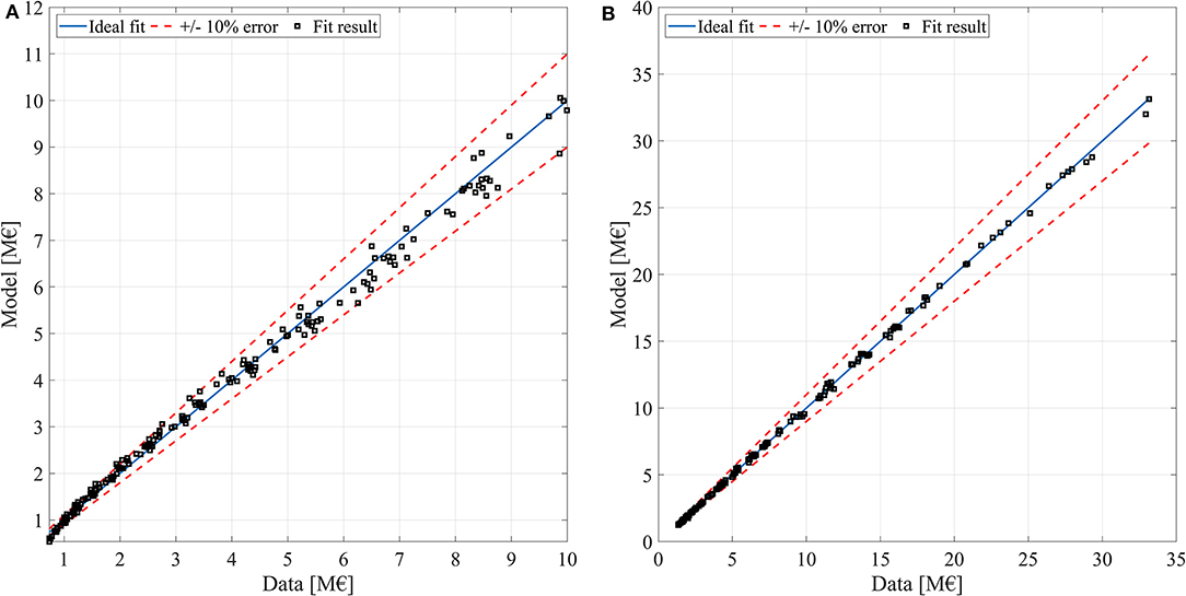
Figure 6. Capacity-related cost and power-related cost fit accuracy. (A) Capacity-related cost ideal fit and fit results. (B) Capacity-related cost ideal fit and fit results.
The cost scaling laws may be useful to generalize the results and for calculating the cost for different TI-PTES configurations. The provided cost scaling laws are defined for ηrt values comprised between 0.5 and 0.9, for Tin,src values comprised between 70 and 80°C, for nominal power input comprised between 500 and 5,000 kWel, and for capacities comprised between 2,000 and 40,000 kWhel. If used outside these boundaries, the accuracy of the cost scaling laws cannot be guaranteed. The cost scaling function parameters are reported in Table 7.
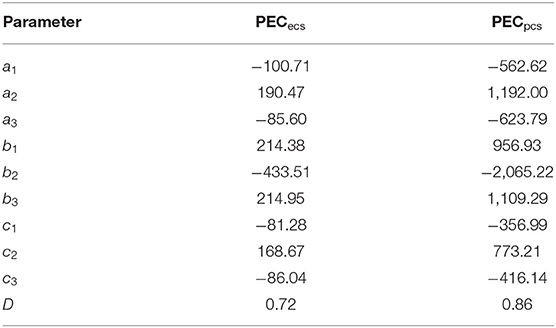
Table 7. TI-PTES cost correlation parameters.
Finally, some TI-PTES configurations, which could be interesting for practical purposes, are reported in Table 8. Here many of the already commented TI-PTES design features may be confirmed, and many additional design features are specified. These results may be useful for a simplified TI-PTES design and for modeling purposes.
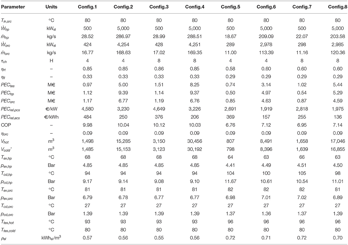
Table 8. TI-PTES exemplificative configurations.
In Table 8, the second law efficiency ηII is also reported. This parameter is defined according to the commonly accepted definition which considers the TI-PTES net power input and output, as well as the energy associated to the heat source (for further details, see Frate et al., 2020). As it resulted, ηII increases with ηrt, but the relative increase tends to zero as ηrt grows. This is because, by moving toward higher ηrt, much higher additional heat (i.e., thermal energy) is required from the heat source. This is confirmed also by the HT-VCHP COP values which increase together with ηrt. COP is a very important parameter to monitor since it controls the ratio between the TI-PTES electric size and thermal size. To achieve satisfactory electric efficiencies, i.e., ηrt ≥ 0.6, the COP must be around 7 or even higher. This means that a very efficient TI-PTES may require a large amount of low-temperature heat. This impacts the costs, which is considered in the current analysis, but it may also pose a limitation to the system size. As a matter of fact, for each unit of electric power, up to 10 units of heat flow rate may be required. This may limit the proposed TI-PTES architectures to small-sized applications whose cost may be relatively high, as it has been demonstrated in this paper.
As discussed above, the TES and the ORC temperature profiles are pretty much constant for the investigated configurations. The TES stores the thermal energy at temperatures always lower than 100°C, such that the water does not need to be pressurized. As a result, the ORC evaporation temperature is almost constant and around 80°C.
From Table 8, the HT-VCHP evaporator is always at a temperature 12–15 K lower than that of the heat source, and the HT-VCHP condenser is always at a temperature 15−20 K higher than that of the heat source. Since the ORC and the TES temperatures are almost constant, the variation of HT-VCHP evaporation and condensation temperature levels is confirmed as the main controlling effect over the trade-off between efficiency and PEC in TI-PTES systems.
In Table 8, the required TES volume for some interesting TI-PTES configurations may be read. As it resulted, volumes from 800 to 30,000 m3 may be found as a function of the size and the efficiency. By considering a cylindrical tank with the height equal to the diameter, the reported volumes may be translated into tanks of heights/diameters comprised between 10 and 33 m.
As demonstrated in previous studies (Dumont et al., 2019; Frate et al., 2020), net electric energy densities [ρel = Ẇhp·τch·ηrt / (Vhot + Vcold)] above 10 kWhel/m3 may be achieved for TI-PTES systems. Such energy-dense configurations may be achieved if lower electrical round-trip efficiency values are assumed as the energy density and the electrical round-trip efficiency are competing features. This is reflected in Table 8, where the resulting energy densities are between 0.55 and 0.72. Furthermore, for similar-sized configurations, by increasing ηrt, it is clear how the TES volume is greatly increased.
Finally, as far as the specific costs are concerned, PECrel,ecs may vary between slightly <150 €/kWh up to slightly <500 €/kWh as a function of the storage capacity. Similarly, the PECrel,pcs may vary between slightly <2,000 €/kW and slightly more than 4,500 €/kW. However, it must be remembered that these are PEC values which should be adjusted to find the total final cost. As discussed in section Performance Parameters, there is a relevant uncertainty over the value of the factor that must be multiplied for the PEC to find the actual final cost. In the best-case scenarios, i.e., for a multiplying factor equal to 1.18 (Turton et al., 2009) or 1.4 (Astolfi et al., 2014b), the energy conservation section cost may end up costing around 160 to 190 €/kWh for large size and around 570 to 670 €/kWh for small size. For the same multiplying factor values, the power conversion section may cost around 2,300 to 2,700 €/kW for large-sized applications and around 5,500 to 6,500 €/kW for small-sized applications.
Discussion
The provided analysis led to identify a realistic cost range for the TI-PTES storage technology. The resulting values may be used to compare the investigated technology with other similar systems which may compete for the same application. As reported in Frate et al. (2019b), other PTES systems based on Brayton and Rankine technologies may achieve efficiencies between 0.5 and 0.6 or slightly higher, but with lower specific costs, up to 180 €/kWh for Brayton systems (Benato and Stoppato, 2018b) and up to 120 €/kWh for Rankine systems (Morandin et al., 2013). For what concerns power-related costs, values around 600–800 €/kW are reported for Brayton technologies, whereas values around 400 €/kW may be found for Rankine systems. As the reported costs are mainly referred to systems in the range 50+ MW, it could be stated that the proposed TI-PTES system may achieve satisfactory economic performance and potentially competitive costs, especially if the capacity-related costs are considered. On the other hand, the cost per kilowatt that resulted for the TI-PTES system is significantly larger, even if the size difference is considered.
As far as small-sized TI-PTES systems are concerned, there is a gap in the literature, to the best of the authors' knowledge, such that benchmark studies are missing. However, it is natural to achieve higher specific cost with smaller sizes, and a system designed to operate in the scale of dozens of megawatts cannot be directly compared with one in the sub-megawatt scale.
As the power-related cost turned out to be so impactful, the solutions proposed in Staub et al. (2018) and Dumont et al. (2019), which aim at using reversible HT-VCHP and ORC equipment, might be very promising. As a matter of fact, the power conversion section represents most of the TI-PTES costs, especially if short storage durations are used (i.e., τch ≤ 6 h). Therefore, by reducing the number of components, large economic benefits might be achieved. The easier approach to this problem is to use the same heat exchangers for both ORC and HT-VCHP where possible, as done in Staub et al. (2018). As demonstrated in Figures 4A,B, this may bring significant benefits as the heat exchangers may represent the majority of PEC. In Dumont et al. (2019), a more ambitious solution is proposed, and the same machine is used for both the HT-VCHP compressor and the ORC expander. This solution was studied only for volumetric devices; therefore, a smaller TI-PTES size target is considered. As shown in Figure 4A, although the possibility of using a reversible machine is interesting, the compressor cost share is quite low compared to the total; thus, the economic advantage of a reversible device may not justify the inherent efficiency losses.
As far as technologies different from the PTES are concerned, the LAES and the CAES systems are usually characterized by a power-related cost roughly comprised between 1,000 and 2,000 €/kW (Gallo et al., 2016; Frate et al., 2019b). These costs may be considered as comparable with those resulting from the TI-PTES analysis, especially because CAES and LAES are usually designed for larger sizes than those investigated here. Furthermore, LAES is characterized by a capacity cost up to 530 €/kWh. Therefore, TI-PTES may represent a cheaper alternative. The same is true in case TI-PTES is compared with CAES. As a matter of fact, CAES may be costlier than TI-PTES if underwater or above-ground small-sized solutions are used. In this case, CAES may be characterized by a capacity cost up to 200 €/kWh (Gallo et al., 2016).
Among the grid-scale storage technologies, the TI-PTES may be compared also to sodium sulfur and flow battery technologies. For these technologies, the cost estimates may vary significantly in literature, and the per kilowatt hour costs comprised roughly between 150 and 1,000 €/kWh may be found (Zakeri and Syri, 2015; Gallo et al., 2016). However, as is common for batteries, the cost per kilowatt is much lower, around 500 €/kW or lower (Zakeri and Syri, 2015; Gallo et al., 2016). This is because the power conversion equipment is much simpler for batteries, whereas for PTES, LAES, and CAES, it is represented by a costly equipment such as compressor, turbines, and heat exchangers.
To provide a fair comparison with all the cited technologies, it must be remembered that the proposed TI-PTES system takes advantage of an additional heat source instead of using an electric input only. Even though the heat source provides a low-grade (i.e., low temperature) thermal contribution, the positive effect on the round-trip efficiency is significant. For this reason, the provided technology comparison must be interpreted in the sense that it suggests that the investigated TI-PTES system is likely to be economically competitive among the other electric storage technologies.
Furthermore, the investigated configurations may also have some crucial advantages over several of the listed storage technologies. As a matter of fact, in TI-PTES, the energy is stored at atmospheric pressure and at 90°C, which makes the storage very safe, easy to build, and with potentially low thermal losses. The storage material is water, which is inexpensive and environmentally neutral. All the components are durable and may withstand up to 20 years of operating life. Finally, the system is based on very known and studied technologies, which are used even in stand-alone applications. All the components are commercially available as of today, such that the TI-PTES technology may achieve high TRL very quickly and without the need for long and costly development studies.
Conclusion
Based on the analysis that has been developed, the following conclusions may be drawn: A TI-PTES system based on regenerated HT-VCHP and ORC was studied. The system is equipped with a two-tank sensible heat storage. The theoretical thermodynamic design of the system was conducted by solving a non-linear multi-objective optimization problem. The design space was explored for several different nominal power ratings (from 500 to 5,000 kW) and for different storage durations (from 4 to 8 h). As the system takes advantage of an additional low-grade heat source, the impact of the source temperature was assessed by assuming values comprised between 60 and 80°C.
Electrical round-trip efficiency ηrt and cost PECtot are two competing features, such that the maximum efficiency configurations are also those that maximize the cost and vice versa. For this reason, the TI-PTES economic performance is characterized from a multicriteria point of view by solving the design optimization problem as a multi-objective one. This led to identify the optimal trade-off configurations (Pareto fronts) as a function of different combinations of nominal power input, storage duration, and heat source temperature level.
By dividing the total cost into capacity- and power-related costs, it was possible to build cost scaling functions that correlate the TI-PTES power rating and its nominal capacity to its final cost. This may allow for a generalization of the results provided in the paper.
Finally, the main findings presented in the paper may be summarized as:
• Tin,src has a significant impact on the maximum achievable TI-PTES ηrt. If ηrt > 0.5 is considered of any practical interest, then Tin,src < 60° C should be avoided;
• The nominal power input impact on cost is non-linear as the relative cost increment decreases with the size. Therefore, the proposed relation between cost and size is a power law;
• Along the Pareto front, for configurations of practical interest, the ORC and the TES temperature profiles are almost constant. Only atmospheric pressure is used for the TES, and the pressurized vessels are never selected in the system design. ORC evaporation temperature is always around 80°C and ηorc resulted to be consistently equal to 0.09;
• Differently from ORC and TES, the HT-VCHP cycle is varied along the Pareto front. This is the main mechanism used by the system to control the cost/efficiency trade-off. For high efficiency, the COP must be high, but this entails an increment in the ratio between electric power and thermal flow rates. In this way, for a given electric power rating, larger TES volumes, larger ORC nominal power out, and larger heat exchanger areas are required; thus, the system costs more. For achieving an efficiency of practical interest, the COP resulted to be at least around 7;
• For small size and low efficiency (0.5 < ηrt < 0.7), the majority of the cost is represented by the TES (around 40%), followed by the ORC (around 35%). The rest of the cost is represented by the HT-VCHP. In this case, a relevant share of the cost is represented by the heat exchanger apparatus such that any solutions that may reduce the number of components may yield significant benefits. For high efficiency (ηrt > 0.7), the cost is more evenly distributed, with each subsystem accounting for around one-third of the cost. Similar conclusions may be drawn also for a larger size. In this case, the ORC expander cost share is significantly reduced since this component has a good economy of scale;
• The resulting cost values were divided into cost per kilowatt and per kilowatt hour. Within the following boundaries, i.e., 70°C < Tin,src < 80°C, 0.5 < ηrt < 0.7, and 500 < Ẇhp < 5,000, cost scaling functions were proposed. The power-related cost resulted to a scale with the installed power rating up to 0.86, whereas the capacity-related cost scales with the capacity up to 0.72;
Some representative configurations were presented with greater detail. In particular, the resulting net electric energy densities are very low, lower than 1 kWhel/m3, such that the resulting TES volumes are relevant. If translated into cylindrical tanks with the height equal to the diameter, the TES tank would go from a diameter of 10 m for a TI-PTES configuration of 500 kWel and 4 h of storage to a diameter of 33 m for a TI-PTES configuration of 5,000 kWel and 8 h of storage.
Data Availability Statement
The datasets generated for this study are available on request to the corresponding author.
Author Contributions
GF contributed to the study conceptualization, methodology development, software development, result analysis and wrote the original draft. LF and UD contributed to the study conceptualization, methodology development, reviewed and edited the original draft.
Funding
Funding of PRA of the University of Pisa is gratefully acknowledged.
Conflict of Interest
The authors declare that the research was conducted in the absence of any commercial or financial relationships that could be construed as a potential conflict of interest.
References
Aneke, M., and Wang, M. (2016). Energy storage technologies and real life applications – a state of the art review. Appl. Energy 179, 350–377. doi: 10.1016/j.apenergy.2016.06.097
Arpagaus, C., Bless, F., Uhlmann, M., Schiffmann, J., and Bertsch, S. S. (2018). High temperature heat pumps: market overview, state of the art, research status, refrigerants, and application potentials. Energy 152, 985–1010. doi: 10.1016/j.energy.2018.03.166
Astolfi, M., Romano, M. C., Bombarda, P., and Macchi, E. (2014a). Binary ORC (Organic Rankine Cycles) power plants for the exploitation of medium-low temperature geothermal sources - Part B: techno-economic optimization. Energy 66, 435–446. doi: 10.1016/j.energy.2013.11.057
Astolfi, M., Romano, M. C., Bombarda, P., and Macchi, E. (2014b). Binary ORC (organic Rankine cycles) power plants for the exploitation of medium–low temperature geothermal sources – Part A: thermodynamic optimization. Energy 66, 423–434. doi: 10.1016/j.energy.2013.11.056
Ayachi, F., Tauveron, N., Tartière, T., Colasson, S., and Nguyen, D. (2016). Thermo-electric energy Storage involving CO2 transcritical cycles and ground heat storage. Appl. Therm. Eng. 108, 1418–1428. doi: 10.1016/j.applthermaleng.2016.07.063
Bejan, A., Tsatsaronis, G., and Moran, M. (1996). Thermal Design and Optimization. New York, NY: Wiley.
Bell, I. H., Wronski, J., Quoilin, S., and Lemort, V. (2014). Pure and pseudo-pure fluid thermophysical property evaluation and the open-source thermophysical property library cool prop. Ind. Eng. Chem. Res. 53, 2498–2508. doi: 10.1021/ie4033999
Benato, A. (2017). Performance and cost evaluation of an innovative pumped thermal electricity storage power system. Energy 138, 419–436. doi: 10.1016/j.energy.2017.07.066
Benato, A., and Stoppato, A. (2018a). Heat transfer fluid and material selection for an innovative pumped thermal electricity storage system. Energy 147, 155–168. doi: 10.1016/j.energy.2018.01.045
Benato, A., and Stoppato, A. (2018b). Pumped thermal electricity storage: a technology overview. Therm. Sci. Eng. Prog. 6, 301–315. doi: 10.1016/j.tsep.2018.01.017
Bitzer (2019). Bitzer Price List. Available online at: https://www.bitzer.de/bg/en/products/screw-compressors/semi-hermetic/for-standard-refrigerants/hs95-series/ (accessed January 10, 2020).
Braimakis, K., and Karellas, S. (2018). Energetic optimization of regenerative Organic Rankine Cycle (ORC) configurations. Energy Convers. Manag. 159, 353–370. doi: 10.1016/j.enconman.2017.12.093
Brückner, S., Liu, S., Miró, L., Radspieler, M., Cabeza, L. F., and Lävemann, E. (2015). Industrial waste heat recovery technologies: an economic analysis of heat transformation technologies. Appl. Energy 151, 157–167. doi: 10.1016/j.apenergy.2015.01.147
Chen, H., Goswami, D. Y., and Stefanakos, E. K. (2010). A review of thermodynamic cycles and working fluids for the conversion of low-grade heat. Renew. Sustain. Energy Rev. 14, 3059–3067. doi: 10.1016/j.rser.2010.07.006
Desrues, T., Ruer, J., Marty, P., and Fourmigu,é, J. F. (2010). A thermal energy storage process for large scale electric applications. Appl. Therm. Eng. 30, 425–432. doi: 10.1016/j.applthermaleng.2009.10.002
Dumont, O., Dickes, R., Ishmael, M., and Lemort, V. (2019). “Mapping of performance of pumped thermal energy storage (Carnot battery) using waste heat recovery,” in 5th International Seminar on ORC Power Systems (Athens).
European Enviroment Agency (2019). European Water Price. Available online at: https://www.eea.europa.eu/data-and-maps/indicators/water-prices (accessed January 11, 2019).
Forman, C., Muritala, I. K., Pardemann, R., and Meyer, B. (2016). Estimating the global waste heat potential. Renew. Sustain. Energy Rev. 57, 1568–1579. doi: 10.1016/j.rser.2015.12.192
Frate, G. F., Antonelli, M., and Desideri, U. (2017a). A novel Pumped Thermal Electricity Storage (PTES) system with thermal integration. Appl. Therm. Eng. 121, 1051–1058. doi: 10.1016/j.applthermaleng.2017.04.127
Frate, G. F., Antonelli, M., and Desideri, U. (2017b). “Pumped Thermal Electricity Storage: An interesting technology for power-to-heat applications,” in ECOS 2017 - The 30th International Conference on Efficiency, COST, Optimization, Simulation and Environmental Impact of Energy Systems July 2-July 6, 2017 (San Diego, CA).
Frate, G. F., Ferrari, L., and Desideri, U. (2019a). Analysis of suitability ranges of high temperature heat pump working fluids. Appl. Therm. Eng. 150, 628–640. doi: 10.1016/j.applthermaleng.2019.01.034
Frate, G. F., Ferrari, L., and Desideri, U. (2019b). “Critical review and economic feasibility analysis of electric energy storage technologies suited for grid scale applications,” in Proceedings of XIV Research & Development in Power Engineering (RDPE) Conference (Warsaw). doi: 10.1051/e3sconf/201913701037
Frate, G. F., Ferrari, L., and Desideri, U. (2020). Multi-criteria investigation of a pumped thermal electricity storage (PTES) system with thermal integration and sensible heat storage. Energy Convers. Manag. 208:112530. doi: 10.1016/j.enconman.2020.112530
Gallo, A. B., Simões-Moreira, J. R., Costa, H. K. M., Santos, M. M., and Moutinho dos Santos, E. (2016). Energy storage in the energy transition context: a technology review. Renew. Sustain. Energy Rev. 65, 800–822. doi: 10.1016/j.rser.2016.07.028
Georgiou, S., Shah, N., and Markides, C. N. (2018). A thermo-economic analysis and comparison of pumped-thermal and liquid-air electricity storage systems. Appl. Energy 226, 1119–1133. doi: 10.1016/j.apenergy.2018.04.128
Howes, J. (2012). “Concept and development of a pumped heat electricity storage device,” in Proceedings of the IEEE 100, 493–503. doi: 10.1109/JPROC.2011.2174529
Jensen, J. K., Ommen, T., Markussen, W. B., Reinholdt, L., and Elmegaard, B. (2015). Technical and economic working domains of industrial heat pumps: Part 2 - Ammonia-water hybrid absorption-compression heat pumps. Int. J. Refrig. 55, 183–200. doi: 10.1016/j.ijrefrig.2015.02.011
Jockenhöfer, H., Steinmann, W. D., and Bauer, D. (2018). Detailed numerical investigation of a pumped thermal energy storage with low temperature heat integration. Energy 145, 665–676. doi: 10.1016/j.energy.2017.12.087
Kim, Y. M., Shin, D. G., Lee, S. Y., and Favrat, D. (2013). Isothermal transcritical CO2 cycles with TES (thermal energy storage) for electricity storage. Energy 49, 484–501. doi: 10.1016/j.energy.2012.09.057
Laughlin, R. B. (2017). Pumped thermal grid storage with heat exchange. J. Renew. Sustain. Energy 9:044103. doi: 10.1063/1.4994054
Lemmens, S. (2016). Cost engineering techniques and their applicability for cost estimation of organic rankine cycle systems. Energies 9, 485–503. doi: 10.3390/en9070485
Lemmon, E. W., Bell, I. H., Huber, M. L., and McLinden, M. O. (2018). NIST Standard Reference Database 23: Reference Fluid Thermodynamic and Transport Properties-REFPROP, Version 10.0. National Institute of Standards and Technology (Gaithersburg, MD).
MathWorks (2019). Constrained Nonlinear Optimization Algorithms. Available online at: https://it.mathworks.com/help/optim/ug/constrained-nonlinear-optimization-algorithms.html#f26684 (accessed August 21, 2019).
McTigue, J. D., White, A. J., and Markides, C. N. (2015). Parametric studies and optimisation of pumped thermal electricity storage. Appl. Energy 137, 800–811. doi: 10.1016/j.apenergy.2014.08.039
Miettinen, K. (1998). Nonlinear Multiobjective Optimization. Boston, MA: Springer US. doi: 10.1007/978-1-4615-5563-6
Morandin, M., Maréchal, F., Mercangöz, M., and Buchter, F. (2012a). Conceptual design of a thermo-electrical energy storage system based on heat integration of thermodynamic cycles – Part A: methodology and base case. Energy 45, 375–385. doi: 10.1016/j.energy.2012.03.031
Morandin, M., Maréchal, F., Mercangöz, M., and Buchter, F. (2012b). Conceptual design of a thermo-electrical energy storage system based on heat integration of thermodynamic cycles – Part B: alternative system configurations. Energy 45, 386–396. doi: 10.1016/j.energy.2012.03.033
Morandin, M., Mercangöz, M., Hemrle, J., Maréchal, F., and Favrat, D. (2013). Thermoeconomic design optimization of a thermo-electric energy storage system based on transcritical CO2 cycles. Energy 58, 571–587. doi: 10.1016/j.energy.2013.05.038
Morgan, R., Nelmes, S., Gibson, E., and Brett, G. (2015). Liquid air energy storage – Analysis and first results from a pilot scale demonstration plant. Appl. Energy 137, 845–853. doi: 10.1016/j.apenergy.2014.07.109
Ommen, T., Jensen, J. K., Markussen, W. B., Reinholdt, L., and Elmegaard, B. (2015). Technical and economic working domains of industrial heat pumps: Part 1 – Single stage vapour compression heat pumps. Int. J. Refrig. 55, 168–182. doi: 10.1016/j.ijrefrig.2015.02.012
Peterson, R. B. (2011). A concept for storing utility-scale electrical energy in the form of latent heat. Energy 36, 6098–6109. doi: 10.1016/j.energy.2011.08.003
Quoilin, S., Broek, M., Van, D.en, Declaye, S., Dewallef, P., and Lemort, V. (2013). Techno-economic survey of organic rankine cycle (ORC) systems. Renew. Sustain. Energy Rev. 22, 168–186. doi: 10.1016/j.rser.2013.01.028
Reddy, K. S., Mudgal, V., and Mallick, T. K. (2018). Review of latent heat thermal energy storage for improved material stability and effective load management. J. Energy Storage 15, 205–227. doi: 10.1016/j.est.2017.11.005
Roskosch, D., and Atakan, B. (2017). Pumped heat electricity storage: potential analysis and orc requirements. Energy Procedia 129, 1026–1033. doi: 10.1016/j.egypro.2017.09.235
Smallbone, A., Jülch, V., Wardle, R., and Roskilly, A. P. (2017). Levelised Cost of Storage for pumped heat energy storage in comparison with other energy storage technologies. Energy Convers. Manag. 152, 221–228. doi: 10.1016/j.enconman.2017.09.047
Song, J., Loo, P., Teo, J., and Markides, C. N. (2020). Thermo-economic optimization of Organic Rankine Cycle (ORC) systems for geothermal power generation: a comparative study of system configurations. Front. Energy Res. 8:6. doi: 10.3389/fenrg.2020.00006
Staub, S., Bazan, P., Braimakis, K., Müller, D., Regensburger, C., Scharrer, D., et al. (2018). Reversible heat pump-organic rankine cycle systems for the storage of renewable electricity. Energies 11:1352. doi: 10.3390/en11061352
Steinmann, W. D. (2014). The CHEST (Compressed Heat Energy STorage) concept for facility scale thermo mechanical energy storage. Energy 69, 543–552. doi: 10.1016/j.energy.2014.03.049
Steinmann, W. D. (2017). Thermo-mechanical concepts for bulk energy storage. Renew. Sustain. Energy Rev. 75, 205–219. doi: 10.1016/j.rser.2016.10.065
Steinmann, W. D., Bauer, D., Jockenhöfer, H., and Johnson, M. (2019). Pumped thermal energy storage (PTES) as smart sector-coupling technology for heat and electricity. Energy 183, 185–190. doi: 10.1016/j.energy.2019.06.058
Turton, R., Bailie, R. C., Whiting, W. B., and Shaeiwitz, J. A. (2009). Analysis, Synthesis and Design of Chemical Processes. Boston, MA: Pearson.
van Kleef, L. M. T., Oyewunmi, O. A., and Markides, C. N. (2019). Multi-objective thermo-economic optimization of organic Rankine cycle (ORC) power systems in waste-heat recovery applications using computer-aided molecular design techniques. Appl. Energy 251:112513. doi: 10.1016/j.apenergy.2019.01.071
Wang, L., Lin, X., Chai, L., Peng, L., Yu, D., and Chen, H. (2019). Cyclic transient behavior of the Joule–Brayton based pumped heat electricity storage: modeling and analysis. Renew. Sustain. Energy Rev. 111, 523–534. doi: 10.1016/j.rser.2019.03.056
Wierzbicki, A. P. (1980). “The use of reference objectives in multiobjective optimization,” in Multiple Criteria Decision Making Theory and Application (Berlin; Heidelberg: Springer), 468–486. doi: 10.1007/978-3-642-48782-8_32
Zakeri, B., and Syri, S. (2015). Electrical energy storage systems: a comparative life cycle cost analysis. Renew. Sustain. Energy Rev. 42, 569–596. doi: 10.1016/j.rser.2014.10.011
Zalba, B., Marín, J. M., Cabeza, L. F., and Mehling, H. (2003). Review on thermal energy storage with phase change: materials, heat transfer analysis and applications. Appl. Therm. Eng. 23, 251–283. doi: 10.1016/S1359-4311(02)00192-8
Nomenclature
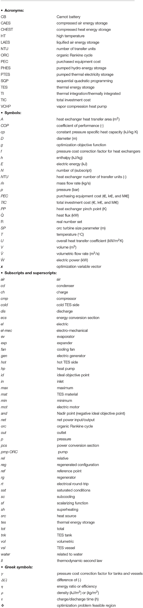
Keywords: pumped thermal electricity storage, multi-criteria economic analysis, optimized design, multi-objective design, high temperature heat pump, organic Rankine cycle, Carnot batteries
Citation: Frate GF, Ferrari L and Desideri U (2020) Multi-Criteria Economic Analysis of a Pumped Thermal Electricity Storage (PTES) With Thermal Integration. Front. Energy Res. 8:53. doi: 10.3389/fenrg.2020.00053
Received: 20 January 2020; Accepted: 17 March 2020;
Published: 21 April 2020.
Edited by:
Zhiwen Ma, National Renewable Energy Laboratory (DOE), United StatesReviewed by:
Xingchao Wang, Colorado School of Mines, United StatesChing-Jen Tang, General Electric, United States
Copyright © 2020 Frate, Ferrari and Desideri. This is an open-access article distributed under the terms of the Creative Commons Attribution License (CC BY). The use, distribution or reproduction in other forums is permitted, provided the original author(s) and the copyright owner(s) are credited and that the original publication in this journal is cited, in accordance with accepted academic practice. No use, distribution or reproduction is permitted which does not comply with these terms.
*Correspondence: Umberto Desideri, dW1iZXJ0by5kZXNpZGVyaUB1bmlwaS5pdA==